


TA37は、医療用の治療台や患者用リフト等に最適です!
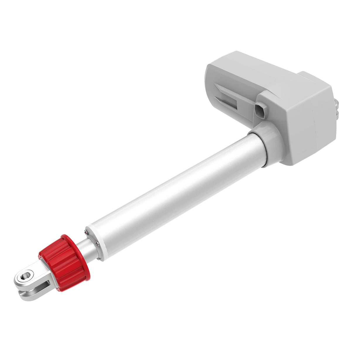
TA37は、当社の高品質医療用アクチュエーターの1つです。 TA37は、要求の厳しい医療用途に推奨されます。 大きな負荷でも安定した速度(定格負荷時)を維持します。 TA37の最大ストロークは1,000mmで、IP等級は最大IP66Wです。 TA37に適した医療用には、治療台や患者用リフトがあります。
【主な特長】
最大負荷:12,000N(Push)
速度(定格負荷時):13.3mm/s(6,000N仕様)
取付寸法:≥ストローク+ 170mm
IP等級:IP66W
認証:IEC60601-1
ストローク:25〜1000mm
オプション:ホールセンサー、手動リリース(患者ホイスト用)
入力電圧:24 / 36V DC(サーマルプロテクター)
色:黒または灰色
使用温度範囲:+ 5°C〜+ 45°C
患者のホイスト用に適しています。
このカタログについて
| ドキュメント名 | 電動リニアアクチュエータ【TA37】 |
|---|---|
| ドキュメント種別 | 製品カタログ |
| ファイルサイズ | 756Kb |
| 登録カテゴリ | |
| 取り扱い企業 | TiMotion Japan株式会社 (この企業の取り扱いカタログ一覧) |
この企業の関連カタログ


このカタログの内容
Page1
TA37
series
Product Segments TA37 is one of our high quality medical actuators. TA37 is recommended for
the demanding force medical applications. It remains stable speed even under
• Care Motion heavy loading. The maximum stroke of TA37 is up to 1000mm and its IP rating
can support up to IP66W. The suitable medical applications for TA37 are
treatment tables or patient hoist systems.
General Features
Max. load 12,000N (push)
Max. speed at max. load 5.3mm/s
Max. speed at no load 23.1mm/s
Retracted length ≥ Stroke + 170mm
IP rating IP66W
Certificate IEC60601-1
Stroke 25~1000mm
Options Hall sensors, manual release
(for patient hoist)
Voltage 24 / 36V DC (thermal protector)
Color Black or grey
Operational temperature range +5°C~+45°C
Suitable for patient hoist application
1
Page2
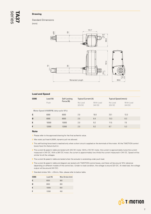
Drawing
Standard Dimensions
(mm)
110.7
32.9
Retracted Length 99.8
Load and Speed
CODE Load (N) Self Locking Typical Current (A) Typical Speed (mm/s)
Force (N)
Push No Load With Load No Load With Load
32V DC 24V DC 32V DC 24V DC
Motor Speed (4100RPM, duty cycle 10%)
C 6000 6000 2.0 10.0 23.1 13.3
D 8000 8000 2.0 8.4 13.3 8.3
E 10000 10000 2.0 9.2 11.5 7.0
F 12000 12000 2.0 9.2 8.7 5.3
Note
1 Please refer to the approved drawing for the final authentic value.
2 Max static pull load 4,000N, dynamic pull not allowed.
3 T his self-locking force level is reached only when a short circuit is applied on the terminals of the motor. All the TiMOTION control
boxes have this feature built-in.
4 T he current & speed in table are tested with 24V DC motor. With a 12V DC motor, the current is approximately twice the current
measured in 24V DC. With a 36V DC motor, the current is approximately two-thirds the current measured in 24V DC. Speed will be
similar for all the voltages.
5 T he current & speed in table are tested when the actuator is extending under push load.
6 The current & speed in table and diagram are tested with TiMOTION control boxes, and there will be around 10% tolerance
depending on different models of the control box. (Under no load condition, the voltage is around 32V DC. At rated load, the voltage
output will be around 24V DC)
7 S tandard stroke: Min. ≥ 25mm, Max. please refer to below table.
CODE Load (N) Max Stroke (mm)
C 6000 900
D 8000 800
E 10000 650
F 12000 450
2
19
ø26
38 50
37.4 32.9
191.4 99.8
TA37
series
Page3
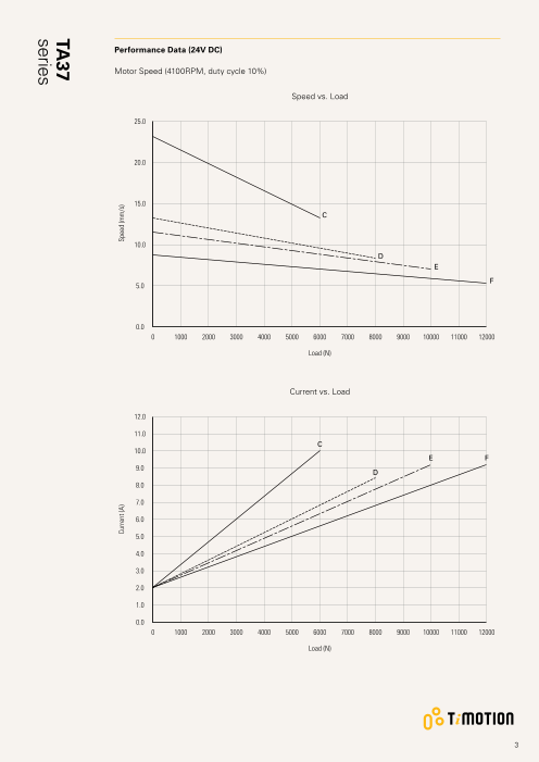
Performance Data (24V DC)
Motor Speed (4100RPM, duty cycle 10%)
Speed vs. Load
25.0
20.0
15.0
C
10.0
D
E
F
5.0
0.0
0 1000 2000 3000 4000 5000 6000 7000 8000 9000 10000 11000 12000
Load (N)
Current vs. Load
12.0
11.0
C
10.0
E F
9.0
D
8.0
7.0
6.0
5.0
4.0
3.0
2.0
1.0
0.0
0 1000 2000 3000 4000 5000 6000 7000 8000 9000 10000 11000 12000
Load (N)
3
Current (A) Speed (mm/s)
TA37
series
Page4
TA37 Ordering Key
TA37
Version: 20210317-J
Voltage 5 = 24V DC, thermal protector 7 = 36V DC, thermal protector
Load and Speed See page 2
Stroke (mm) See page 2
Retracted Length See page 6
(mm)
Rear Attachment 1 = A luminum casting, U clevis, slot 6.2, depth 19.5, hole 4 = Aluminum casting, U clevis, slot 8.2, depth 19.5, hole
(mm) 10.2 12.2
See page 6 2 = A luminum casting, U clevis, slot 6.2, depth 19.5, hole C = Aluminum casting, U clevis, slot 8.2, depth 19.5, hole
12.2 10.2, with plastic T-busing
3 = Aluminum casting, U clevis, slot 8.2, depth 19.5, hole
10.2
Front Attachment 1 = Punched hole on inner tube + plastic cap, without 9 = Aluminum casting, U clevis, slot 6.2, depth 17.0, hole
(mm) slot, hole 10.2, with plastic bush 10.2, with plastic T-bushing
See page 7 2 = Punched hole on inner tube + plastic cap, without K = Aluminum casting, U clevis, slot 8.2, depth 17.0, hole
slot, hole 12.2 10.2
7 = Aluminum casting, U clevis, slot 6.2, depth 17.0, hole L = Aluminum casting, U clevis, slot 8.2, depth 17.0, hole
10.2 12.2
8 = Aluminum casting, U clevis, slot 6.2, depth 17.0, hole M = Aluminum casting, U clevis, slot 8.2, depth 17.0,
12.2 hole 10.2, with plastic T-bushing
Direction of 1 = 0° 3 = 90°
Rear Attachment
(Counterclockwise)
See page 7
Color 1 = Black 2 = Pantone 428C
IP Rating 1 = Without 2 = IP54 3 = IP66 5 = IP66W
Special Functions 0 = Without (standard) 2 = Standard push only
for Spindle Sub- 1 = Safety nut 3 = Standard push only + safety nut
Assembly
Functions for 1 = Two switches at full retracted / extended positions to cut current
Limit Switches 2 = Two switches at full retracted / extended positions to cut current + third one in between to send signal
See page 8 3 = Two switches at full retracted / extended positions to send signal
4 = Two switches at full retracted / extended positions to send signal + third one in between to send signal
5 = Two switches at full retracted / extended positions to send signal (For TC1, TC8, TC10, TC14, TC21)
Output Signals 0 = Without 2 = Hall sensor*2
Connector 1 = DIN 6P, 90° plug 4 = Big 01P, plug F = DIN 6P, 180° plug P = Molex 8P, 90° plug,
See page 8 2 = Tinned leads E = Molex 8P, plug G = Audio plug without anti-clip
Cable Length (mm) 0 = Straight, 100 3 = Straight, 1000 6 = Straight, 2000
1 = Straight, 500 4 = Straight, 1250 7 = Curly, 200
2 = Straight, 750 5 = Straight, 1500 8 = Curly, 400
Note
1 TA37 is designed especially for push applications, not suitable for pull applications.
4
Page5
TA37 Patient Hoist Ordering Key
TA37
Version: 20210317-J
Voltage 5 = 24V DC, thermal protector 7 = 36V DC, thermal protector
Load and Speed E = 10000N F = 12000N
Stroke (mm) See page 2
Retracted Length See page 6
(mm)
Rear Attachment C = A luminum casting, U clevis, slot 8.2, depth 19.5, hole 10.2, with plastic T-busing
(mm)
See page 6
Front Attachment F = Aluminum casting, U clevis, slot 8.2, depth 17.0, hole 10.2, with plastic T-bushing, for Manual Release
(mm)
See page 7
Direction of 1 = 0°
Rear Attachment
(Counterclockwise)
See page 7
Color 1 = Black 2 = Pantone 428C
IP Rating 1 = Without 2 = IP54 3 = IP66 5 = IP66W
Emergency Release 5 = Manual release
Function
Special Functions 6 = Mechanical push only + safety nut
for Spindle Sub-
Assembly
Functions for 1 = Two switches at full retracted / extended positions to cut current
Limit Switches
See page 8
Output Signals 0 = Without
Connector 1 = DIN 6P, 90° plug F = DIN 6P, 180° plug G = Audio plug
See page 8
Cable Length (mm) 1 = Straight, 500 3 = Straight, 1000 5 = Straight, 1500
2 = Straight, 750 4 = Straight, 1250 6 = Straight, 2000
Note
1 TA37 is designed especially for push applications, not suitable for pull applications.
5
Page6
TA37 Ordering Key Appendix
Retracted Length (mm)
1. Calculate A+B = Y
2. Retracted length needs to ≥ Stroke + Y
A. B.
Front Attach. General For Patient Hoist Stroke (mm) Load (N)
1, 2 170 - General Patient
Hoist
7, 8, 9, K, L, M 178 - = 4000 = 6000 = 8000 = 10000 = 12000
F - 267 25~150 - - - +5 +10 -
151~200 - - +5 +10 +15 -
201~250 - +5 +10 +15 +20 -
251~300 +5 +10 +15 +20 +25 +5
301~350 +10 +15 +20 +25 +30 +10
351~400 +15 +20 +25 +30 +35 +15
401~450 +20 +25 +30 +35 +40 +20
451~500 +25 +30 +35 +40 +45 +25
501~550 +30 +35 +40 +45 +50 +30
551~600 +35 +40 +45 +50 +55 +35
601~650 +40 +45 +50 +55 +60 +40
651~700 +45 +50 +55 +60 +65 +45
701~750 +50 +55 +60 +65 +70 +50
751~800 +55 +60 +65 +70 +75 +55
801~850 +60 +65 +70 +75 +80 +60
851~900 +65 +70 +75 +80 +85 +65
901~950 +70 +75 +80 +85 +90 +70
951~1000 +75 +80 +85 +90 +95 +75
Rear Attachment (mm)
1 = Aluminum casting, U clevis, slot 2 = A luminum casting, U clevis, slot 3 = Aluminum casting, U clevis, slot 4 = Aluminum casting, U clevis, slot
6.2, depth 19.5, hole 10.2 6.2, depth 19.5, hole 12.2 8.2, depth 19.5, hole 10.2 8.2, depth 19.5, hole 12.2
ø10.2 ø12.2 ø10.2 ø12.2
R14 R14 R14 R14
19.5 19.5 19.5 19.5
C = A luminum casting, U clevis, slot
8.2, depth 19.5, hole 10.2, with
plastic T-busing
ø10.2
R14
19.5
6
8.2 28 6.2 28
27.5 27.1
6.2 28
27.1
8.2 28
27.1
8.2 28
27.1
Page7
TA37 Ordering Key Appendix
Front Attachment (mm)
1 = Punched hole on inner tube + 2 = Punched hole on inner tube + 7 = Aluminum casting, U clevis, slot 8 = Aluminum casting, U clevis, slot
plastic cap, without slot, hole plastic cap, without slot, hole 6.2, depth 17.0, hole 10.2 6.2, depth 17.0, hole 12.2
10.2, with plastic bush 12.2
ø10.2 ø12.2 ø10.2 ø12.2
17 17
9 = A luminum casting, U clevis, slot F = A luminum casting, U clevis, slot K = Aluminum casting, U clevis, slot L = Aluminum casting, U clevis, slot
6.2, depth 17.0, hole 10.2, with 8.2, depth 17.0, hole 10.2, with 8.2, depth 17.0, hole 10.2 8.2, depth 17.0, hole 12.2
plastic T-bushing plastic T-bushing, for Manual
Release
ø10.2
ø10.2 ø10.2 ø12.2
17 19 17 17
M = Aluminum casting, U clevis, slot
8.2, depth 17.0, hole 10.2, with
plastic T-bushing
ø10.2
17
Direction of Rear Attachment (Counterclockwise)
1 = 0° 3 = 90°
Hole
90
º
0º
7
27.8 27.8 32 ø29.7
8.2 6.2
ø26 ø26
ø26
Hole 27.5 32 ø29.727.5
8.2
ø26
26
25.8 25.8
8.2 6.2
ø26 ø26
25.8 25.8
8.2 6.2
ø26 ø26
Page8
TA37 Ordering Key Appendix
Functions for Limit Switches
Wire Definitions
CODE Pin
1 (Green) 2 (Red) 3 (White) 4 (Black) 5 (Yellow) 6 (Blue)
1 extend (VDC+) N/A N/A N/A retract (VDC+) N/A
2 extend (VDC+) N/A middle switch pin B middle switch pin A retract (VDC+) N/A
3 extend (VDC+) common upper limit switch N/A retract (VDC+) lower limit switch
4 extend (VDC+) common upper limit switch medium limit switch retract (VDC+) lower limit switch
5 extend (VDC+) N/A upper limit switch common retract (VDC+) lower limit switch
Connector
1 = DIN 6P, 90° plug 2 = Tinned leads 4 = Big 01P, plug E = Molex 8P, plug
F = DIN 6P, 180° plug G = Audio plug P = Molex 8P, 90°plug, without
anti-clip
Terms of Use
The user is responsible for determining the suitability of TiMOTION products for a specific application.
TiMOTION products are subject to change without prior notice.
8