


TiMOTIONのTA16シリーズラインアクチュエーターは、特に低ノイズでコンパクト性が必要な医療用に設計されています。
オプションでIP66規格対応と位置フィードバックのためのホールセンサー対応が可能です。IEC60601-1、ES60601-1、IEC60601-1-2、UL962、EMC認証を取得しています。
【主な特長】
最大負荷:3,500N (Push/Pull)
速度(定格負荷時):6.2mm/sec
取付寸法:≥ ストローク+112mm
最大速度:23.5mm/s
IP等級:IP66
認証:IEC60601-1、ES60601-1、IEC60601-1-2、UL962、EMC
ストローク:20~600mm
オプション:POT、ホールセンサー
入力電圧:12、24、36、48V DC
色:銀色
使用温度範囲:+5°C~+45°C
非常に静音、小型で簡単設置
このカタログについて
| ドキュメント名 | 電動リニアアクチュエータ【TA16】 |
|---|---|
| ドキュメント種別 | 製品カタログ |
| ファイルサイズ | 1.3Mb |
| 登録カテゴリ | |
| 取り扱い企業 | TiMotion Japan株式会社 (この企業の取り扱いカタログ一覧) |
この企業の関連カタログ


このカタログの内容
Page1
TA16
series
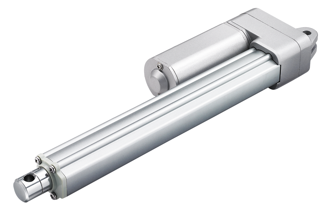
Product Segments TiMOTION’s TA16 series linear actuator is similar to the TA2 linear actuator, but
is specifically designed for low-noise medical applications where a compact
• Care Motion linear actuator is needed. It is available with optional IP66 protection and Hall
• Comfort Motion sensors for position feedback. Certificates for the TA16 include IEC60601-1,
ES60601-1, IEC60601-1-2, UL962, and EMC.
• Ergo Motion
• Industrial Motion General Features
Max. load 3,500N (push/pull)
MaVx. speed at max. load 6.2mm/s
Max. speed at no load 23.5mm/s
Retracted length ≥ Stroke + 112mm
IP rating IP66
Certificate IEC60601-1, ES60601-1, IEC60601-1-2,
UL962, EMC
Stroke 20~600mm
Options POT, Hall sensor(s)
Voltage 12, 24, 36, 48V DC
Color Silver
Operational temperature range +5°C~+45°C
at full performance
With very low noise, small size for easy installation
Suitable for patient hoist application
1
Page2
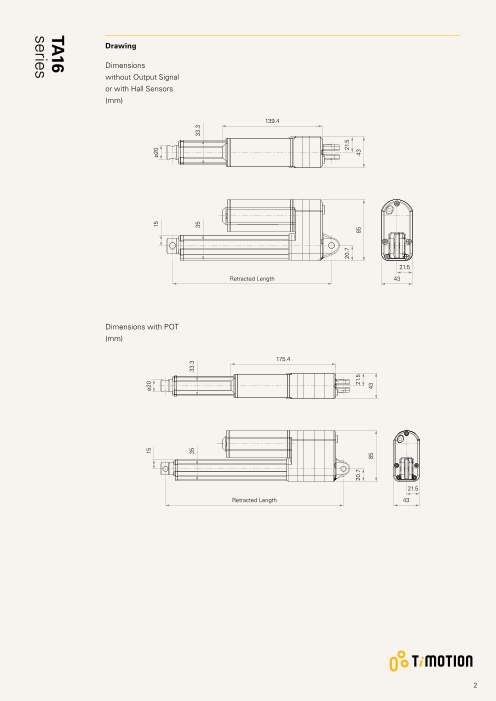
Drawing
Dimensions
without Output Signal
or with Hall Sensors
(mm)
139.4
21.5
Retracted Length 43
Dimensions with POT
(mm)
175.4
21.5
Retracted Length 43
2
15 ø20
15 ø20
35 33.3
35 33.3
20.7 21.5
20.7 21.5 85 43
85 43
TA16
series
Page3
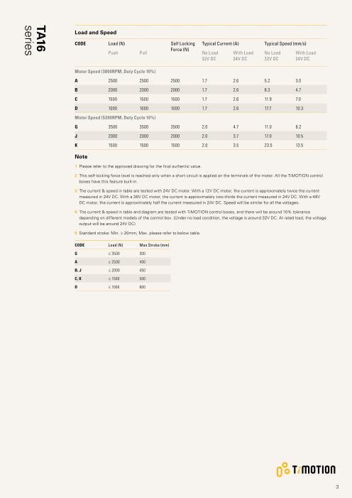
Load and Speed
CODE Load (N) Self Locking Typical Current (A) Typical Speed (mm/s)
Force (N)
Push Pull No Load With Load No Load With Load
32V DC 24V DC 32V DC 24V DC
Motor Speed (3800RPM, Duty Cycle 10%)
A 2500 2500 2500 1.7 2.6 5.2 3.0
B 2000 2000 2000 1.7 2.6 8.3 4.7
C 1500 1500 1500 1.7 2.6 11.9 7.0
D 1000 1000 1000 1.7 2.6 17.7 10.3
Motor Speed (5200RPM, Duty Cycle 10%)
G 3500 3500 3500 2.0 4.7 11.0 6.2
J 2000 2000 2000 2.0 3.7 17.0 10.5
K 1500 1500 1500 2.0 3.5 23.5 13.5
Note
1 Please refer to the approved drawing for the final authentic value.
2 This self-locking force level is reached only when a short circuit is applied on the terminals of the motor. All the TiMOTION control
boxes have this feature built-in.
3 The current & speed in table are tested with 24V DC motor. With a 12V DC motor, the current is approximately twice the current
measured in 24V DC. With a 36V DC motor, the current is approximately two-thirds the current measured in 24V DC. With a 48V
DC motor, the current is approximately half the current measured in 24V DC. Speed will be similar for all the voltages.
4 The current & speed in table and diagram are tested with TiMOTION control boxes, and there will be around 10% tolerance
depending on different models of the control box. (Under no load condition, the voltage is around 32V DC. At rated load, the voltage
output will be around 24V DC)
5 S tandard stroke: Min. ≥ 20mm, Max. please refer to below table.
CODE Load (N) Max Stroke (mm)
G ≤ 3500 300
A ≤ 2500 400
B, J ≤ 2000 450
C, K ≤ 1500 500
D ≤ 1000 600
3
TA16
series
Page4
Performance Data (24V DC Motor)
Motor Speed (3800RPM, Duty Cycle 10%)
Speed vs. Load
50.0
40.0
30.0
20.0
10.0 D
C
B
A
0.0
0 1000 2000 3000 4000 5000
Load (N)
Current vs. Load
5.0
4.0
3.0
D C B A
2.0
1.0
0.0
0 1000 2000 3000 4000 5000
Load (N)
4
Current (A) Speed (mm/s)
TA16
series
Page5
Performance Data (24V DC Motor)
Motor Speed (5200RPM, Duty Cycle 10%)
Speed vs. Load
50.0
40.0
30.0
20.0
K
J
10.0
G
0.0
0 1000 2000 3000 4000 5000
Load (N)
Current vs. Load
6.0
5.0
G
4.0 J
K
3.0
2.0
1.0
0.0
0 1000 2000 3000 4000 5000
Load (N)
5
Current (A) Speed (mm/s)
TA16
series
Page6
TA16 Ordering Key
TA16
Version: 20200710-K
Voltage 1 = 12V DC 2 = 24V DC 3 = 36V DC 4 = 48V DC
Load and Speed See page 3
Stroke (mm) See page 3
Retracted Length See page 7
(mm)
Rear Attachment 1 = A luminum casting, U clevis, width 6.0, depth 12.2, hole 6.4, one piece casting with gear box
(mm) 2 = Aluminum casting, U clevis, width 6.0, depth 12.2, hole 8.0, one piece casting with gear box
See page 8 3 = A luminum casting, U clevis, width 6.0, depth 12.2, hole 10.0, one piece casting with gear box
Front Attachment 1 = Aluminum casting, no slot, hole 6.4 5 = Aluminum casting, U clevis, width 6.0, depth 13.0,
(mm) 2 = Aluminum casting, no slot, hole 8.0 hole 8.0
See page 8 3 = A luminum casting, no slot, hole 10.0 6 = Aluminum casting, U clevis, width 6.0, depth 13.0,
hole 10.0
4 = A luminum casting, U clevis, width 6.0, depth 13.0,
hole 6.4
Direction of 1 = 90° 2 = 0°
Rear Attachment
(Counterclockwise)
See page 8
IP Rating 1 = Without 2 = IP54 3 = IP66
Functions for 1 = Two switches at full retracted / extended positions to cut current
Limit Switches 2 = Two switches at full retracted / extended positions to cut current + 3rd LS to send signal
See page 9 3 = Two switches at full retracted / extended positions to send signal
4 = Two switches at full retracted / extended positions to send signal + 3rd LS to send signal
Special Functions 0 = Without (Standard) 2 = Standard push only
for Spindle Sub- 1 = Safety nut 3 = Standard push only + safety nut
Assembly
Output Signals 0 = Without 1 = POT 4 = Hall sensor * 1 5 = Hall sensor * 2
Connector 1 = DIN 6P, 90° plug C = Y cable (For direct cut system, water proof, anti pull) G = Audio plug
See page 9 2 = Tinned leads E = Molex 8P, plug
4 = Big 01P, plug F = DIN 6P, 180° plug
Cable Length (mm) 0 = Straight, 100 3 = Straight, 1000 6 = Straight, 2000 B~H = For direct cut system
1 = Straight, 500 4 = Straight, 1250 7 = Curly, 200 See page 9
2 = Straight, 750 5 = Straight, 1500 8 = Curly, 400
6
Page7
TA16 Ordering Key Appendix
Retracted Length (mm)
1. Calculate A+B+C+D = Y
2. Retracted length needs to ≥ Stroke + Y
A. Rear / Front Attachment C. Load V.S. Spindle Functions
Front Rear Attachment Spindle Load (N)
Attachment Functions
1, 2, 3 A, B G C, D, J, K
1, 2, 3 +112 0 - - -
4, 5, 6 +122 1 +10 +5 +10
2 +2 +2 +2
B. Load V.S. Stroke 3 +12 +7 +12
Stroke (mm) Load (N)
< 3500 = 3500 D. Output Signals
20~150 - +13 CODE
151~200 +8 +21 0, 4, 5 -
201~250 +8 +21 1 +36
251~300 +13 +26
301~350 +13 +26
351~400 +18 +31
401~450 +23 +36
451~500 +28 +41
501~550 +33 +46
551~600 +38 +51
7
Page8
TA16 Ordering Key Appendix
Rear Attachment (mm)
1 = Aluminum casting, U clevis, 2 = Aluminum casting, U clevis, 3 = Aluminum casting, U clevis,
width 6.0, depth 12.2, hole 6.4, width 6.0, depth 12.2, hole 8.0, width 6.0, depth 12.2, hole 10.0,
one piece casting with gear box one piece casting with gear box one piece casting with gear box
ø6.4 ø8 ø10
R11 R11 R11
12.2 12.2 12.2
Front Attachment (mm)
1 = A luminum casting, no slot, hole 2 = A luminum casting, no slot, hole 3 = Aluminum casting, no slot, hole 4 = Aluminum casting, U clevis,
6.4 8.0 10.0 width 6.0, depth 13.0, hole 6.4
ø6.4 ø8 ø10 ø6.4
9 9 9 13
5 = Aluminum casting, U clevis, 6 = A luminum casting, U clevis,
width 6.0, depth 13.0, hole 8.0 width 6.0, depth 13.0, hole 10.0
ø8 ø10
13 13
Direction of Rear Attachment (Counterclockwise)
1 = 90° 2 = 0°
8
ø20
6.1 ø20
6
21 35.8
ø20
6.1 ø20
6
21 35.8
ø20
6
21 35.8
ø20
6.1
Page9
TA16 Ordering Key Appendix
Functions for Limit Switches
Wire Definitions
CODE Pin
1 (Green) 2 (Red) 3 (White) 4 (Black) 5 (Yellow) 6 (Blue)
1 extend (VDC+) N/A N/A N/A retract (VDC+) N/A
2 extend (VDC+) N/A middle switch pin B middle switch pin A retract (VDC+) N/A
3 extend (VDC+) common upper limit switch N/A retract (VDC+) lower limit switch
4 extend (VDC+) common upper limit switch medium limit switch retract (VDC+) lower limit switch
Connector
1 = DIN 6P, 90° plug 2 = Tinned leads 4 = Big 01P, plug
4
50
C = Y cable (For direct cut system, water proof, anti pull)
L3 Cable length for direct cut system (mm)
CODE L1 L2 L3
B 100 100 100
L2 L1
C 100 1000 400
D 100 2700 500
E 1000 100 100
F 100 600 1000
G 1500 1000 1000
H 100 100 1200
E = Molex 8P, plug F = DIN 6P, 180° plug G = Audio plug
Terms of Use
The user is responsible for determining the suitability of TiMOTION products for a specific application.
TiMOTION products are subject to change without prior notice.
9