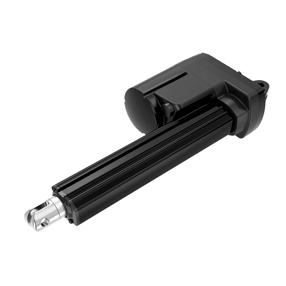


TiMOTIONのMA2シリーズ リニアアクチュエーターは、特に過酷な動作環境や堅牢性と耐久性が必要とされる用途用に設計されています。
IP69Kの保護構造により、高圧水ジェット、ホコリやその他の固体汚染物質の侵入に対する耐久性を保証します。ストロークを調整する事ができるリードスイッチをオプションでご用意しています。制御と動作の精度を向上させるため、必要な用途に合わせて数多くある多様なフィードバックオプションによりMA2をカスタマイズすることもできます。 MA2に適した用途例: 散布機、収穫機、穀物処理機、コンバイン、トラクターなどの農業機械。 商業芝刈り機、洗浄機、掃除機、資材運搬機器、家畜換気システムなどの産業用途。
【主な特長】
最大負荷:6,000N (Push/Pull)
最大速度定格負荷時:6.1mm/s
最大速度無負荷時:52.5mm/s
取付寸法:≥ ストローク+131mm
IP等級:IP69K
認証:UL73、EMC
ストローク:≧ 25~1000mm
オプション:ホールセンサー、 POT
入力電圧:12V DC, 24V DC, 36V DC; 12V DC, 24V DC, 36 V DC (過電流保護)
使用温度範囲:-30˚C~+65˚C
最適使用温度範囲:+5˚C~+45˚C
このカタログについて
| ドキュメント名 | 電動リニアアクチュエータ【MA2】 |
|---|---|
| ドキュメント種別 | 製品カタログ |
| ファイルサイズ | 524.7Kb |
| 登録カテゴリ | |
| 取り扱い企業 | TiMotion Japan株式会社 (この企業の取り扱いカタログ一覧) |
この企業の関連カタログ


このカタログの内容
Page1
MA2
series
Product Segments TiMOTION’s MA2 series electric linear actuator was specifically designed for
applications that face harsh working environments and require heavy-duty and
• Industrial Motion durability. Its IP69K protection ensures it will withstand high-pressure water jets
and the ingress of dust and other solid contaminants. The MA2 electric cylinder
actuator also has optional Reed switches along the outer tube which allow users
to adjust the stroke length. For improved control and accuracy of motion, the
MA2 can be customized with many different feedback options depending on your
application requirements. Example applications suitable for the MA2: Agricultural
equipment such as spreaders, harvesters, grain handlers, combines, and tractors.
Commercial and industrial applications such as commercial lawn mowers,
scrubbers and sweepers, material handling equipment and livestock ventilation
systems.
General Features
Max. load 6,000N (push/pull)
Max. speed at max. load 14mm/s (Ball screw, DC motor)
Max. speed at no load 52.5mm/s
Retracted length ≥ Stroke + 131mm
IP rating IP69K
Certificate UL73, EMC
Stroke ≥ 25~1000mm
Options Hall sensors, POT, manual drive, Reed sensor
on the outer tube
Voltage 12V DC, 24V DC, 36V DC;
12V DC, 24V DC, 36V DC (thermal control)
Operational temperature range -30˚C~+65˚C
Operational temperature range +5˚C~+45˚C
at full performance
1
Page2
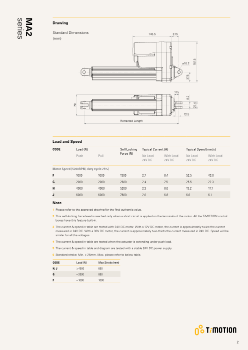
Drawing
Standard Dimensions 145.5 27.5
(mm)
ø10.2
17.5
12.5
Retracted Length
Load and Speed
CODE Load (N) Self Locking Typical Current (A) Typical Speed (mm/s)
Force (N)
Push Pull No Load With Load No Load With Load
24V DC 24V DC 24V DC 24V DC
Motor Speed (5200RPM, duty cycle 25%)
F 1000 1000 1300 2.7 8.4 52.5 43.0
G 2000 2000 2600 2.4 7.5 25.5 22.3
H 4000 4000 5200 2.3 8.0 13.2 11.1
J 6000 6000 7800 2.0 6.8 6.6 6.1
Note
1 Please refer to the approved drawing for the final authentic value.
2 This self-locking force level is reached only when a short circuit is applied on the terminals of the motor. All the TiMOTION control
boxes have this feature built-in.
3 The current & speed in table are tested with 24V DC motor. With a 12V DC motor, the current is approximately twice the current
measured in 24V DC. With a 36V DC motor, the current is approximately two-thirds the current measured in 24V DC. Speed will be
similar for all the voltages.
4 The current & speed in table are tested when the actuator is extending under push load.
5 The current & speed in table and diagram are tested with a stable 24V DC power supply.
6 S tandard stroke: Min. ≥ 25mm, Max. please refer to below table.
CODE Load (N) Max Stroke (mm)
H, J ≥ 4000 600
G = 2000 800
F = 1000 1000
2
79
8.2 37.5
25.4 151.5
MA2
series
Page3
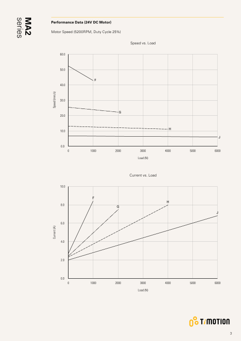
Performance Data (24V DC Motor)
Motor Speed (5200RPM, Duty Cycle 25%)
Speed vs. Load
60.0
50.0
F
40.0
30.0
G
20.0
H
10.0
J
0.0
0 1000 2000 3000 4000 5000 6000
Load (N)
Current vs. Load
10.0
F
H
8.0 G
J
6.0
4.0
2.0
0.0
0 1000 2000 3000 4000 5000 6000
Load (N)
3
Current (A) Speed (mm/s)
MA2
series
Page4
MA2 Ordering Key
MA2
Version: 20200623-E
Voltage 1 = 12V DC 5 = 24VDC, thermal protector
2 = 24V DC 6 = 12VDC, thermal protector
3 = 36V DC 7 = 36VDC, thermal protector
Load and Speed See page 2
Stroke (mm) See page 2
Retracted Length See page 5
(mm)
Rear Attachment 1 = Aluminum casting, clevis U, slot 8.2, depth 12.5, hole 10.2
(mm) 2 = Aluminum casting, clevis U, slot 8.2, depth 15.0, hole 10.2
See page 6 3 = A luminum casting, clevis U, slot 8.2, depth 15.0, hole 12.8
4 = A luminum casting, clevis U, slot 8.2, depth 15.0, hole 12.2
Front Attachment 1 = Iron inner tube with punched hole, without slot, hole 10.2
(mm) 2 = Iron inner tube with punched hole, without slot, hole 12.2
See page 6 3 = I ron inner tube with punched hole, without slot, hole 12.8
4 = A luminum casting, clevis U, slot 8.2, depth 15.0, hole 10.2
5 = A luminum casting, clevis U, slot 8.2, depth 15.0, hole 12.2
6 = A luminum casting, clevis U, slot 8.2, depth 15.0, hole 12.8
K = Rod end bearing, hole 12.8
Direction of 1 = 90° 2 = 0°
Installation
(Counterclockwise)
See page 6
Functions for 1 = Two switches at full retracted / extended positions to cut current
Limit Switches 2 = Two switches at full retracted / extended positions to cut current + third one in between to send signal
3 = Two switches at full retracted / extended positions to send signal
6 = Two switches at full retracted / extended positions to cut current + send signal
Reed Sensor on the 0 = Without 1 = Reed sensor*1 2 = Reed sensor*2
Outer Ttube
Output Signal 0 = Without 1 = POT 5 = Hall sensor*2
Connector 2 = Tinned leads
See page 7
Cable Length (mm) 1 = Straight, 500 2 = Straight, 1000 3 = Straight, 1500 4 = Straight, 2000
IP Rating 1 = Without 3 = IP66 8 = IP69K
2 = IP54 6 = IP66D
Manual Drive 0 = Without 1 = With
T-Smart 0 = Without
4
Page5
MA2 Ordering Key Appendix
Retracted Length (mm)
1. Calculate A+B+C = Y
2. Retracted length needs to ≥ Stroke + Y
A. Rear/ Front Attachment B. Stroke (mm)
Front Rear Attachment 25~150 -
Attachment
1 2, 3, 4 151~200 -
1, 2, 3 +131 +134 201~250 +10
4, 5, 6 +161 +164 251~300 +20
K +178 +181 301~350 +30
351~400 +40
C. Output Signal 401~450 +50
0, 5 - 451~500 +60
1 +20 501~550 +70
551~600 +80
601~650 +90
651~700 +100
701~750 +110
751~800 +120
801~850 +130
851~900 +140
901~950 +155
951~1000 +160
5
Page6
MA2 Ordering Key Appendix
Rear Attachment (mm)
1 = Aluminum casting, clevis U, slot 2 = Aluminum casting, clevis U, slot 3 = Aluminum casting, clevis U, slot 4 = Aluminum casting, clevis U, slot
8.2, depth 12.5, hole 10.2 8.2, depth 15.0, hole 10.2 8.2, depth 15.0, hole 12.8 8.2, depth 15.0, hole 12.2
ø10.2 ø10.2 ø12.8 ø12.2
17.5 20.5 20.5 20.5
12.5 15 15 15
Front Attachment (mm)
1 = I ron inner tube with punched 2 = Iron inner tube with punched 3 = Iron inner tube with punched 4 = Aluminum casting, clevis U, slot
hole, without slot, hole 10.2 hole, without slot, hole 12.2 hole, without slot, hole 12.8 8.2, depth 15.0, hole 10.2
ø10.2
ø10.2 ø12.2 ø12.8
15
5 = Aluminum casting, clevis U, slot 6 = A luminum casting, clevis U, slot K = Rod end bearing, hole 12.8
8.2, depth 15.0, hole 12.2 8.2, depth 15.0, hole 12.8
ø12.2 ø12.8 ø12.8
15 15
Direction of Rear Attachment (Counterclockwise)
1 = 90° 2 = 0°
6
8.2
ø28
8.2
ø28
25.4
8.2
ø28
8.2
ø28
25.4
16
ø28
8.2
ø28
25.4
8.2
8.2
ø28
25.4
Page7
MA2 Ordering Key Appendix
Connector
2 = Tinned leads
4
50
Terms of Use
The user is responsible for determining the suitability of TiMOTION products for a specific application.
TiMOTION products are subject to change without prior notice.
7