


TiMOTIONのTL3シリーズは、3段式リフティングコラムで、高いモーメント強度と高推力設計により安定した垂直昇降を提供します。
TL3は工学的な設計プロセスを経て多くの駆動パーツを使用しており、従来のパンタグラフ式昇降機構から置き換えることで、より安全でかつ省スペース化を実現します。3段階の伸縮設計が、短い取付寸法と安定性を高めながらも、ロングストロークを可能とします。
【主な特長】
最大負荷: 4,000N
最大曲げモーメント(動荷重): 1,000Nm
最大曲げモーメント(静荷重): 2,000Nm
速度(定格負荷時): 39mm/sec
取付寸法: ≥ ストローク/2 + 150mm
コラムの寸法: 177.4x150.7 mm
ストローク: 250~1200mm
認証: IEC60601-1、EMC
オプション: POT、ホールセンサー、ダイレクトカットシステム
使用温度範囲: +5°C~+45°C
このカタログについて
| ドキュメント名 | 電動昇降装置【TL3】 |
|---|---|
| ドキュメント種別 | 製品カタログ |
| ファイルサイズ | 1.4Mb |
| 登録カテゴリ | |
| 取り扱い企業 | TiMotion Japan株式会社 (この企業の取り扱いカタログ一覧) |
この企業の関連カタログ


このカタログの内容
Page1
TL3
series
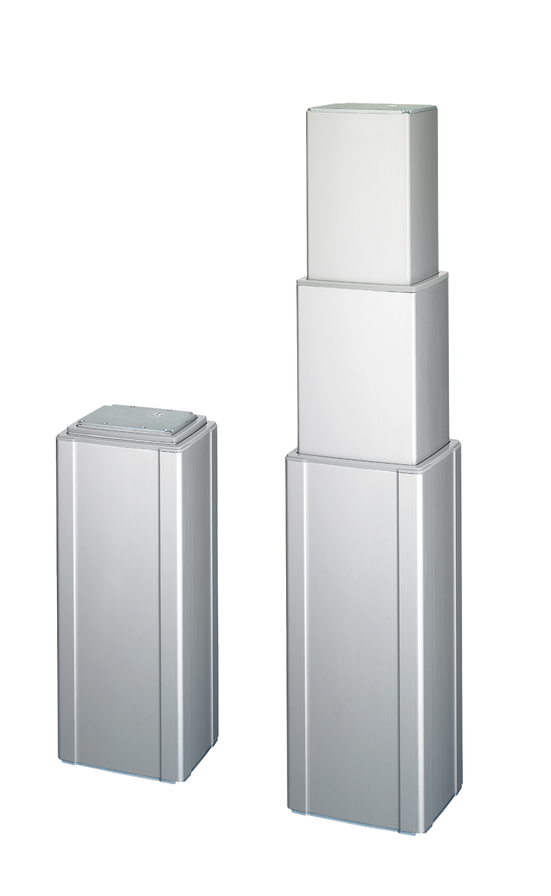
Product Segments The TL3 columns from TiMOTION are made up of three extruded aluminum
tubes of rectangular shape that give the system great stability and a high stroke
• Care Motion with reduced retracted length. This electric lifting column allows for an easy
• Comfort Motion integration into many height adjustable workstation applications, such as an
exam chair in healthcare industry.
• Ergo Motion
• Industrial Motion General Features
Max. load & self - locking force 4,000N (push)
Max. dynamic bending moment 1,000Nm
Max. static bending moment 2,000Nm
Max. speed at max. load 13.7mm/s
Max. speed at no load 39mm/s
Retracted length ≥ Stroke / 2+150mm
IP rating IPX6
Dimension of outer tube 3-stage, 177.4*150.7mm rectangular
Stroke 250~1200mm
Certificate IEC60601-1, EMC
Options POT, Hall sensors, direct cut system
Operational temperature range +5°C~+45°C
1
Page2
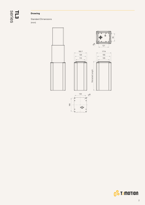
Drawing
Standard Dimensions
(mm)
121
150.7 177.4
130 155
110 135
133
M8
2
160
Retracted Length M
8
95
TL3
series
Page3
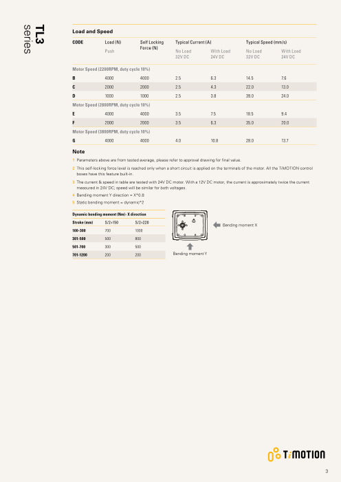
Load and Speed
CODE Load (N) Self Locking Typical Current (A) Typical Speed (mm/s)
Force (N)
Push No Load With Load No Load With Load
32V DC 24V DC 32V DC 24V DC
Motor Speed (2200RPM, duty cycle 10%)
B 4000 4000 2.5 6.3 14.5 7.6
C 2000 2000 2.5 4.3 22.0 13.0
D 1000 1000 2.5 3.8 39.0 24.0
Motor Speed (2800RPM, duty cycle 10%)
E 4000 4000 3.5 7.5 18.5 9.4
F 2000 2000 3.5 6.3 35.0 20.0
Motor Speed (3800RPM, duty cycle 10%)
G 4000 4000 4.0 10.8 28.0 13.7
Note
1 Parameters above are from tested average, please refer to approval drawing for final value.
2 This self-locking force level is reached only when a short circuit is applied on the terminals of the motor. All the TiMOTION control
boxes have this feature built-in.
3 T he current & speed in table are tested with 24V DC motor. With a 12V DC motor, the current is approximately twice the current
measured in 24V DC; speed will be similar for both voltages.
4 Bending moment Y direction = X*0.8
5 Static bending moment = dynamic*2
Dynamic bending moment (Nm)- X direction
Stroke (mm) S/2+150 S/2+220
Bending moment X
100-300 700 1000
301-500 500 800
501-700 300 500
701-1200 200 200 Bending moment Y
3
TL3
series
Page4
Performance Data (24V DC Motor)
Motor Speed (2200RPM, Duty cycle 10%)
Speed vs. Load
40.0
35.0
30.0
D
25.0
20.0
15.0 C
10.0 B
5.0
0.0
0 500 1000 1500 2000 2500 3000 3500 4000
Load (N)
Current vs. Load
10.0
8.0
B
6.0
C
D
4.0
2.0
0.0
0 500 1000 1500 2000 2500 3000 3500 4000
Load (N)
4
Current (A) Speed (mm/s)
TL3
series
Page5
Performance Data (24V DC Motor)
Motor Speed (2800RPM, Duty cycle 10%)
Speed vs. Load
40.0
35.0
30.0
25.0 F
20.0
15.0
E
10.0
5.0
0.0
0 500 1000 1500 2000 2500 3000 3500 4000
Load (N)
Current vs. Load
10.0
8.0 E
F
6.0
4.0
2.0
0.0
0 500 1000 1500 2000 2500 3000 3500 4000
Load (N)
5
Current (A) Speed (mm/s)
TL3
series
Page6
Performance Data (24V DC Motor)
Motor Speed (3800RPM, Duty cycle 10%)
Speed vs. Load
35.0
30.0
25.0
20.0
G
15.0
10.0
5.0
0.0
0 500 1000 1500 2000 2500 3000 3500 4000
Load (N)
Current vs. Load
G
10.0
8.0
6.0
4.0
2.0
0.0
0 500 1000 1500 2000 2500 3000 3500 4000
Load (N)
6
Current (A) Speed (mm/s)
TL3
series
Page7
TL3 Ordering Key - Top End Socket
TL3
Version: 20200421-U
Voltage 1 = 12V DC 5 = 24V DC, thermal control
Load and Speed See page 3
Stroke (mm) 250~1200
Retracted Length See page 10
(mm)
Cable Exit 1 = T op end socket
See page 10
Special Functions 0 = Without (Standard) 1 = Safety nut
for Spindle
Sub-assembly
Functions for Limit 1 = Two switches at full retracted / extended positions to cut current
Switches 3 = Two switches at full retracted / extended positions to send signal
See page 11
IP Rating 1 = Without 2 = IPX4 3 = IPX6
Output Signals 0 = Without 2 = Hall sensors*2 3 = POT
Connector 1 = DIN 6P, socket
See page 11
Cable Length (mm) 0 = Without (The corresponding extension cable TEC needs to be ordered seperately*)
Note: please contact TiMOTION before making an order
Color 1 = Black 2 = Matte silver
Tubes Direction 0 = Thinner on top
See page 12
Grounding Function 0 = Without 1 = With
Note
1 The TL3 is designed especially for push applications, not suitable for pull applications.
7
Page8
TL3 Ordering Key - Side Cable
TL3
Version: 20200421-U
Voltage 1 = 12V DC 5 = 24V DC, thermal control
Load and Speed See page 3
Stroke (mm) 250~1200
Retracted Length See page 10
(mm)
Cable Exit 2 = Bottom side cable 3 = Top side cable 4 = Top (to TC) + Bottom (to TH) side cable
See page 10
Special Functions 0 = Without (Standard) 1 = Safety nut
for Spindle
Sub-assembly
Functions for Limit 1 = Two switches at full retracted / extended positions to cut current
Switches 3 = Two switches at full retracted / extended positions to send signal
See page 11
IP Rating 1 = Without 2 = IPX4 3 = IPX6
Output Signals 0 = Without 2 = Hall sensors*2 3 = POT
Connector 1 = DIN 6P, 90° plug F = DIN 6P, 180° plug H = Molex 8P 180°
See page 11 2 = Tinned leads G = Molex 8P 90°
Cable Length (mm) 1 = Straight, 500 3 = Straight, 1000 5 = Straight, 1500 7 = Straight, 2000
2 = Straight, 750 4 = Straight, 1250 6 = Straight, 1750
Color 1 = Black (Black cable set) 3 = Silver (Black cable set)
2 = Silver (428C color cable set)
Tubes Direction 0 = Thinner on top 1 = Wider on top Note: If "top+bottom cable" in Cable Exit section is
See page 12 selected , could only select #0
Grounding Function 0 = Without 1 = With
Note
1 The TL3 is designed especially for push applications, not suitable for pull applications.
8
Page9
TL3 Ordering Key - Direct Cut
TL3
Version: 20200421-U
Voltage 5 = 24V DC, thermal protector
Load and Speed See page 3
Stroke (mm) 100~1200
Retracted Length See page 10
(mm)
Cable Exit B = Top side - for TH; Bottom side - for TP
See page 10 C = Bottom side - Y cable, for TH + TP
D = Top side - for the 2nd column; Bottom side - for TH & TP; direct cut operation with 2 columns
E = Top side - for the 2nd column & TH; Bottom side - for TP; direct cut operation with 2 columns
Special Functions 0 = Without (Standard) 1 = Safety nut
for Spindle
Sub-assembly
Functions for Limit 1 = Two switches at full retracted / extended positions to cut current
Switches
See page 11
IP Rating 1 = Without 2 = IPX4 3 = IPX6
Output Signals 0 = Without
Connector C = Direct cut, water proof, anti-pull
See page 11
Cable Length (mm) B = Cable exit #B, L2 = L3 = 100 D = Cable exit #D, L2 = L3 = L4 = 100
See page 12 C = Cable exit #C, L1 = L2 = L3 = 100 E = Cable exit #E, L2 = L3 = L4 = 100
Color 1 = Black (With black cable set) 3 = Matte silver (With black cable set)
2 = Matte silver (With 428C color cable set)
Tubes Direction 0 = Thinner on top 1 = Wider on top
See page 12
Grounding Function 0 = Without 1 = With
Note
1 The TL3 is designed especially for push applications, not suitable for pull applications.
9
Page10
TL3 Ordering Key Appendix
Retracted Length (mm)
1. Retracted length needs to ≥ A+B+C
A. Load (N) 1000 2000 4000
Stroke / 2+150 or Stroke / 2+220
Note
1 The minimum retracted length generated by the formula - Stroke / 2+150
applies to the minimum bending moment rating. Please refer to the left column
of the “Dynamic bending moment chart “ on page 3.
B. Cable Exit
CODE Top End Socket Bottom Side Cable Top Side Cable Top + Bottom side cable Direct Cut
1 - - - - -
2 - - - - -
3 - - +15 - -
B - - - +35 -
B, D, E - - - - +35
C - - - - -
C. When with POT (When without POT, C = 0)
Cable Exit Code Top End Bottom Side Cable Top Side
Socket Cable
1 +40 - -
2 - +40 -
3 - - +40
Cable Exit
1 = T op end socket 2 = B ottom side cable
Socket
3 = Top side cable
4 = Top(to TC)+Bottom(to TH) side
cable
10
Page11
TL3 Ordering Key Appendix
Cable Exit
B = Top side - for TH; Bottom side - C = Bottom side - Y cable, for TH + TP D = Top side - for the 2nd column; E = Top side - for the 2nd column &
for TP Bottom side - for TH & TP; direct TH; Bottom side - for TP; direct
cut operation with 2 columns cut operation with 2 columns
Functions for Limit Switches
Wire Definitions
CODE Pin
1 (Green) 2 (Red) 3 (White) 4 (Black) 5 (Yellow) 6 (Blue)
1 extend (VDC+) N/A N/A N/A retract (VDC+) N/A
3 extend (VDC+) common upper limit switch N/A retract (VDC+) lower limit switch
Connector
1 = DIN 6P, socket (Top end socket) 1 = DIN 6P, 90° plug (Side cable) 2 = Tinned leads F = DIN 6P, 180° plug
4
50
G = Molex 8P 90° H = Molex 8P 180°
C = Direct cut, water proof, anti-pull
For TH: For TP: For Columm 2:
long DIN 5P (Pin array 240°), long DIN 5P (Pin array 240°), long DIN 6P (Pin array 240°),
180° socket (with anti-pull clip) 180° plug (with O-ring) 180° plug (with anti-pull clip)
11
Page12
TL3 Ordering Key Appendix
Cable Length (mm)
B = Cable exit #B, L2 = L3 = 100 C = Cable exit #C, L1 = L2 = L3 = 100 D, E = Cable exit #D, #E, L2 = L3 = L4 = 100
L2 L3 L3 L2 L3 L4
TL3
L2 L1
TP TH TH TP TP TH Column 2
Tubes Direction
0 = Thinner on top 1 = Wider on top
Terms of Use
The user is responsible for determining the suitability of TiMOTION products for a specific application.
TiMOTION products are subject to change without prior notice.
12