


TiMOTIONのMA1シリーズリニアアクチュエーターは、耐久性、長寿命が必要な用途に適しています。大型機械、産業用機械、オフロード車などの使用に適しています。
IP66ダイナミックレベルを必要とする用途で使う事ができます。オプション品として、AC電源、ボールスクリューまたはACMEスピンドル、機械式または電磁式ブレーキ、負荷制限クラッチまたは制限スイッチがあります。
【主な特長】
スピンドル:ACMEまたはボールスクリュー
最大負荷:4,500N (Push/Pull)
速度(定格負荷時):14.3mm/sec(ボールスクリュー、DCモーター、2,500N仕様)
取付寸法:≥ストローク+160mm(POTなし)
IP等級:IP69K
認証:UL73、EMC
ストローク:20~1000mm (ACME)、50~800mm (ボールスクリュー )
オプション:過負荷クラッチ、ホールセンサー、POT、手動クランク機能
入力電圧:12 / 24 / 36V DC;110 / 220V AC
色:黒
使用温度範囲:-30°C~+65°C
機械式または電磁ブレーキ
過酷な使用(Duty cycle 25%)、腐食耐性
このカタログについて
| ドキュメント名 | 電動リニアアクチュエータ【MA1】 |
|---|---|
| ドキュメント種別 | 製品カタログ |
| ファイルサイズ | 1.3Mb |
| 登録カテゴリ | |
| 取り扱い企業 | TiMotion Japan株式会社 (この企業の取り扱いカタログ一覧) |
この企業の関連カタログ


このカタログの内容
Page1
MA1
series
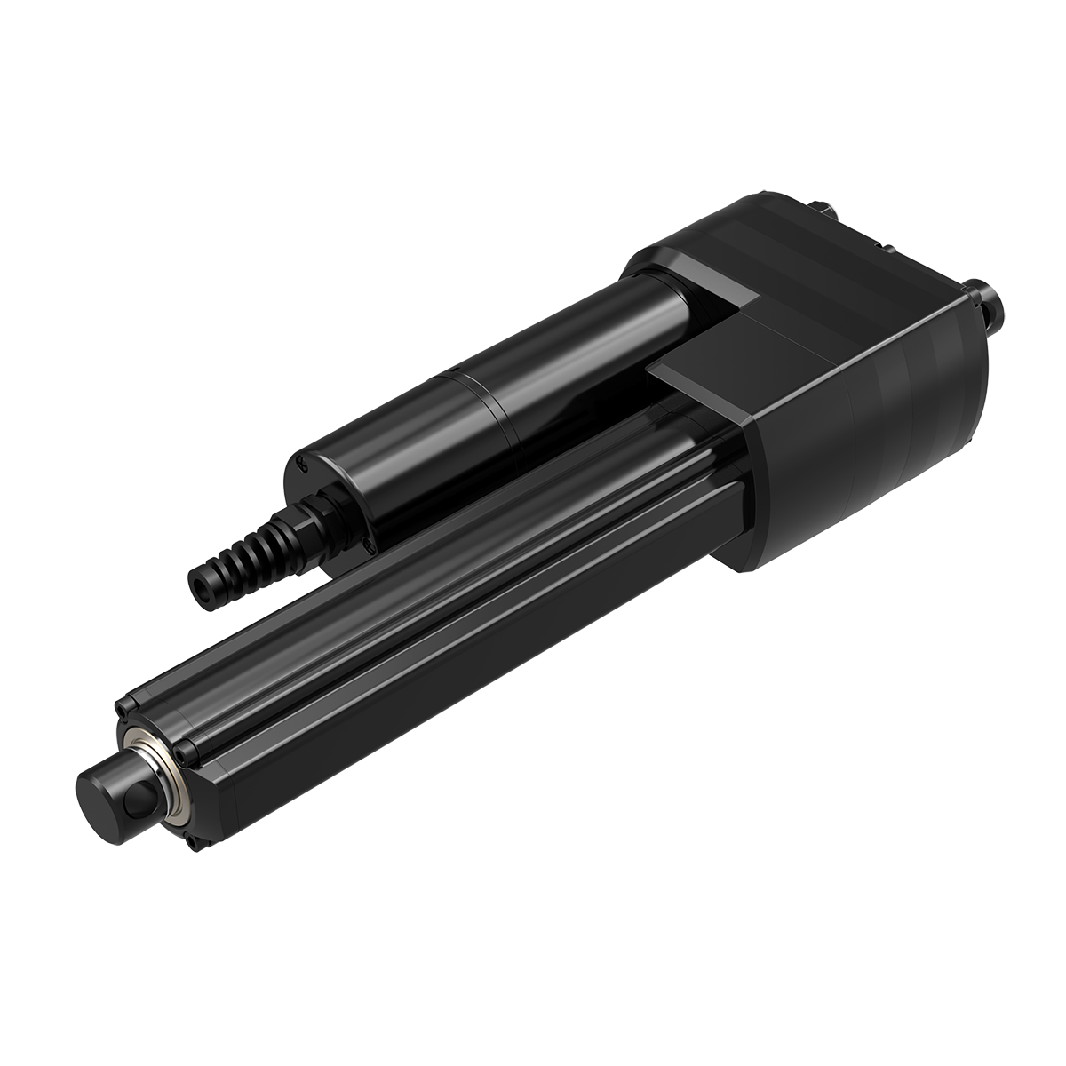
Product Segments TiMOTION’s MA1 series linear actuator is the proven choice for applications
requiring a durable, long life solution. Specifically designed for harsh working
• Industrial Motion environments, the MA1 linear actuator is ideal for use in heavy-duty machinery,
industrial equipment and off road vehicles. This linear actuator has been
certified for applications requiring IP69K compliance. Available options for the
MA1 linear actuator include AC or DC power, ball or acme spindles, mechanical
or electrical braking and a load limiting clutch or limit switches.
General Features
Max. load ACME screw: 2,500N (push / pull)
Ball screw: 4,500N (push / pull)
Max. speed at max. load 14.3mm/s (ACME screw, DC motor)
14mm/s (Ball screw, DC motor)
Max. speed at no load 58.5mm/s (Ball screw, DC motor)
Retracted length ≥ Stroke + 160mm (ACME screw, without POT)
≥ Stroke + 201mm (Ball screw, without POT)
IP rating IP69K
Certificate UL73, EMC
Stroke 20~1000mm (ACME screw);
50~800mm (Ball screw)
Options Overload clutch, electromagnetic brake,
Hall sensors, POT, manual crank function
Voltage 12 / 24 / 36V DC; 110 / 220V AC
Spindle ACME or Ball screw
Color Black
Operational temperature range -30°C~+65°C
Operational temperature range +5°C~+45°C
at full performance
Mechanical or electromagnetic brake
Higher duty cycle (25%), corrosion proof
1
Page2
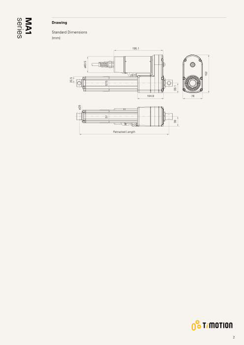
Drawing
Standard Dimensions
(mm)
195.1
104.8 78
Retracted Length
2
25.5
ø28
ø63.5
51 57.5
39 39.1
152
MA1
series
Page3
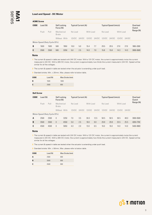
Load and Speed - DC Motor
ACME Screw
CODE Load (N) Self Locking Typical Current (A) Typical Speed (mm/s) Overload
Force (N) Clutch
Range (N)
Push Pull Mechenical No Load With Load No Load With Load
Brake
Without With 12VDC 24VDC 12VDC 24VDC 12VDC 24VDC 12VDC 24VDC
Motor Speed (Duty Cycle 25%)
B 1500 1500 500 1950 10.0 5.0 15.4 7.7 29.5 29.5 27.0 27.0 1800~3300
C 2500 2500 500 3250 5.0 2.5 14.0 7.0 15.8 15.8 14.3 14.3 3000~5500
Note
1 T he current & speed in table are tested with 24V DC motor. With a 12V DC motor, the current is approximately twice the current
measured in 24V DC. With a 36V DC motor, the current is approximately two-thirds the current measured in 24V DC. Speed will be
similar for all the voltages.
2 The current & speed in table are tested when the actuator is extending under push load.
3 Standard stroke: Min. ≥ 20mm, Max. please refer to below table.
CODE Load (N) Max Stroke (mm)
B 1500 1000
C 2500 800
Ball Screw
CODE Load (N) Self Locking Typical Current (A) Typical Speed (mm/s) Overload
Force (N) Clutch
Range (N)
Push Pull Mechenical No Load With Load No Load With Load
Brake
Without With 12VDC 24VDC 12VDC 24VDC 12VDC 24VDC 12VDC 24VDC
Motor Speed (Duty Cycle 25%)
A 2500 2500 0 3250 7.0 3.5 30.0 12.5 58.5 58.5 36.5 48.0 3000~5500
B 3500 3500 0 4550 5.0 2.5 18.0 9.0 29.8 29.8 25.5 25.5 4200~7700
C 4500 4500 0 5850 4.0 2.0 13.0 6.5 16.0 16.0 14.0 14.0 5400~9900
Note
1 The current & speed in table are tested with 24V DC motor. With a 12V DC motor, the current is approximately twice the current
measured in 24V DC. With a 36V DC motor, the current is approximately two-thirds the current measured in 24V DC. Speed will be
similar for all the voltages.
2 The current & speed in table are tested when the actuator is extending under push load.
3 Standard stroke: Min. ≥ 50mm, Max. please refer to below table.
CODE Load (N) Max Stroke (mm)
A 2500 800
B 3500 600
C 4500 600
3
MA1
series
Page4
Load and Speed - AC Motor
ACME Screw
CODE Load (N) Self Locking Typical Current (A) Typical Speed (mm/s) Overload
Force (N) Clutch
Range (N)
Push Pull Mechenical No Load With Load No Load With Load
Brake
Without With 110VAC 220VAC 110VAC 220VAC 110VAC 220VAC 110VAC 220VAC
Motor Speed (Duty Cycle 25%)
B 1500 1500 500 1950 1.9 0.9 2.0 1.0 26.1 22.5 23.0 21.0 1800~3300
C 2500 2500 500 3250 1.9 0.9 2.0 1.0 14.1 12.0 12.8 11.2 3000~5500
Note
1 The current & speed in table are tested when the actuator is extending under push load.
2 Standard stroke: Min. ≥ 20mm, Max. please refer to below table.
CODE Load (N) Max Stroke (mm)
B 1500 1000
C 2500 800
Ball Screw
CODE Load (N) Self Locking Typical Current (A) Typical Speed (mm/s) Overload
Force (N) Clutch
Range (N)
Push Pull Mechenical No Load With Load No Load With Load
Brake
Without With 110VAC 220VAC 110VAC 220VAC 110VAC 220VAC 110VAC 220VAC
Motor Speed (Duty Cycle 25%)
A 2500 2500 0 3250 2.0 0.9 2.5 1.3 53.0 46.0 38.5 40.0 3000~5500
B 3500 3500 0 4550 1.9 0.9 2.1 1.1 27.0 23.5 22.5 21.5 4200~7700
C 4500 4500 0 5850 1.9 0.9 2.0 1.0 14.5 12.0 13.0 11.5 5400~9900
Note
1 The current & speed in table are tested when the actuator is extending under push load.
2 S tandard stroke: Min. ≥ 50mm, Max. please refer to below table.
CODE Load (N) Max Stroke (mm)
A 2500 800
B 3500 600
C 4500 600
4
MA1
series
Page5
Performance Data (12V DC Motor)
ACME Screw (Duty Cycle 25%)
Speed vs. Load
35.0
30.0
B
25.0
20.0
15.0 C
10.0
5.0
0.0
0 1000 2000 3000 4000
Load (N)
Current vs. Load
17.0
16.0 B
15.0
C
14.0
13.0
12.0
11.0
10.0
9.0
8.0
7.0
6.0
5.0
4.0
3.0
2.0
1.0
0.0
0 1000 2000 3000 4000
Load (N)
5
Current (A) Speed (mm/s)
MA1
series
Page6
Performance Data (24V DC Motor)
ACME Screw (Duty Cycle 25%)
Speed vs. Load
35.0
30.0
B
25.0
20.0
15.0 C
10.0
5.0
0.0
0 1000 2000 3000 4000
Load (N)
Current vs. Load
9.0
8.0 B
C
7.0
6.0
5.0
4.0
3.0
2.0
1.0
0.0
0 1000 2000 3000 4000
Load (N)
6
Current (A) Speed (mm/s)
MA1
series
Page7
Performance Data (12V DC Motor)
Ball Screw (Duty Cycle 25%)
Speed vs. Load
65.0
60.0
55.0
50.0
45.0
40.0
A
35.0
30.0
25.0 B
20.0
15.0 C
10.0
5.0
0.0
0 1000 2000 3000 4000 5000 6000
Load (N)
Current vs. Load
35.0
A
30.0
25.0
20.0 B
15.0
C
10.0
5.0
0.0
0 1000 2000 3000 4000 5000 6000
Load (N)
7
Current (A) Speed (mm/s)
MA1
series
Page8
Performance Data (24V DC Motor)
Ball Screw (Duty Cycle 25%)
Speed vs. Load
65.0
60.0
55.0
50.0 A
45.0
40.0
35.0
30.0
25.0 B
20.0
15.0 C
10.0
5.0
0.0
0 1000 2000 3000 4000 5000 6000
Load (N)
Current vs. Load
14.0
13.0 A
12.0
11.0
10.0
B
9.0
8.0
7.0 C
6.0
5.0
4.0
3.0
2.0
1.0
0.0
0 1000 2000 3000 4000 5000 6000
Load (N)
8
Current (A) Speed (mm/s)
MA1
series
Page9
Performance Data (110V AC Motor)
ACME Screw (Duty Cycle 25%)
Speed vs. Load
35.0
30.0
25.0
B
20.0
15.0
C
10.0
5.0
0.0
0 1000 2000 3000 4000
Load (N)
Current vs. Load
3.0
2.0
B C
1.0
0.0
0 1000 2000 3000 4000
Load (N)
9
Current (A) Speed (mm/s)
MA1
series
Page10
Performance Data (220V AC Motor)
ACME Screw (Duty Cycle 25%)
Speed vs. Load
30.0
25.0
B
20.0
15.0
C
10.0
5.0
0.0
0 1000 2000 3000 4000
Load (N)
Current vs. Load
2.0
B C
1.0
0.0
0 1000 2000 3000 4000
Load (N)
10
Current (A) Speed (mm/s)
MA1
series
Page11
Performance Data (110V AC Motor)
Ball Screw (Duty Cycle 25%)
Speed vs. Load
60.0
55.0
50.0
45.0
40.0 A
35.0
30.0
25.0
B
20.0
15.0 C
10.0
5.0
0.0
0 1000 2000 3000 4000 5000 6000
Load (N)
Current vs. Load
4.0
3.0
A
B
2.0 C
1.0
0.0
0 1000 2000 3000 4000 5000 6000
Load (N)
11
Current (A) Speed (mm/s)
MA1
series
Page12
Performance Data (220V AC Motor)
Ball Screw (Duty Cycle 25%)
Speed vs. Load
55.0
50.0
45.0
40.0 A
35.0
30.0
25.0
B
20.0
15.0
C
10.0
5.0
0.0
0 1000 2000 3000 4000 5000 6000
Load (N)
Current vs. Load
3.0
2.0
A
B
1.0 C
0.0
0 1000 2000 3000 4000 5000 6000
Load (N)
12
Current (A) Speed (mm/s)
MA1
series
Page13
MA1 Ordering Key
MA1
Version: 20200710-E
Spindle Type A = ACME Screw B = BALL Screw
Voltage 1 = 12V DC 3 = 36V DC 5 = 220V AC 50Hz
2 = 24V DC 4 = 110V AC 60Hz
Load and Speed See page 3 See page 4
Stroke (mm) See page 3 See page 4
Retracted Length See page 14
(mm)
Rear Attachment 1 = #45 Steel CNC, without slot, hole 13.0
(mm)
See page 14
Front Attachment 1 = #45 Steel CNC, without slot, hole 13.0
(mm)
See page 14
Direction of 1 = 90° (Standard) 2 = 0°
Rear Attachment
(Counterclockwise)
See page 15
Functions for 0 = Without (Needs to choose overload clutch)
Limit Switches 1 = Two switches at full retracted / extended positions to cut current
2 = Two switches at full retracted / extended positions to send signal
Overload Clutch 0 = Without 1 = With
Mechanical Brake 0 = Without 1 = With (Not support the control box with PWM speed adjustment function, such as
See page 15 slow start / stop or sync)
Electromagnetic 0 = Without (Standard) 1 = With
Brake
See page 15
IP Rating 6 = IP66D 8 = IP69K
Manual Drive 0 = Without 1 = With
Output Signals 0 = Without 1 = POT 5 = Hall sensors * 2
See page 16
Connector 1 = Tinned leads
Cable Length (mm) 1 = Straight, 500
13
Page14
MA1 Ordering Key Appendix
Retracted Length (mm)
1. Calculate A+B+C = Y
2. Retracted length needs to ≥ Stroke + Y
A. Type B. Mechanical Brake
ACME, DC Ball, DC ACME, AC Ball, AC ACME, DC Ball, DC ACME, AC Ball, AC
+160 +201 +160 +201 0 - - - -
1 +35 - +35 -
C. Output Signals
ACME, DC Ball, DC ACME, AC Ball, AC
0 - - - -
1 +36 +40 +36 +40
5 - - +36 +40
Rear Attachment (mm)
1 = #45 Steel CNC, without slot, hole
13.0
ø13
14
16.3
Front Attachment (mm)
1 = # 45 Steel CNC, without slot, hole
13.0
11.5
ø13
14
ø28
ø28
ø25.4
Page15
MA1 Ordering Key Appendix
Direction of Rear Attachment (Counterclockwise)
1 = 90° (Standard) 2 = 0°
Mechanical Brake
0 = Without 1 = With (Ball Screw's standard option)
17.3 53 51.8 53
Electromagnetic Brake
0 = Without (Standard, DC) 0 = Without (Standard, AC) 1 = With (DC)
195.1 286.8 227.1
38 113.7 105 138.4 70 113.7
15
ø63.5
ø87
ø63.5
Page16
MA1 Ordering Key Appendix
Output Signals
Wire Definitions AWG Output Signal Code
0. Without 1. POT 5. 2 Hall
DC Motor Motor Side Black 26 - - GND
Blue 26 - - S2
White 26 - - S1
Red 26 - - +5V
Red 14 Stretch+ Stretch+ Stretch+
Black 14 Retract+ Retract+ Retract+
Gear Box Side Red 26 - pin 1 -
White 26 - pin 2 -
Black 26 - pin 3 -
AC Motor Motor Side Black 18 Retract+ Retract+ Retract+
Grey 18 Stretch+ Stretch+ Stretch+
Brown 18 PCBA+ PCBA+ PCBA+
Blue 18 Neutral Neutral Neutral
Green/Yellow 18 GND GND GND
Gear Box Side Red 20 - pin1 +5V
White 20 - pin2 S1
Blue 20 - - S2
Black 20 - pin3 GND
POT
Motor Side Gear Box Side Red
White
Black
Terms of Use
The user is responsible for determining the suitability of TiMOTION products for a specific application.
TiMOTION products are subject to change without prior notice.
16