


TA2Pシリーズリニアアクチュエーターは、コンパクトサイズですが定格負荷3,500Nを実現しています。
高出力モーターに加えて、複数のフィードバックセンサーを選択できます。IEC / ES 60601-1、UL73認証を取得しています。
【主な特長】
入力電圧:12、24、36V DCまたは12、24V DC (PTC)
最大負荷:3,500N (Push)、2,000N (Pull)
速度(定格負荷時):56.5mm/sec(250N仕様)
ストローク:20~1000mm
取付寸法:ストローク+108mm(ホールセンサーあり、または出力信号なし)
色:銀色
認証:IEC60601-1、ES60601-1、EN 61000-6-1、EN 61000-6-3、UL73
IP等級:最高IP66D
使用温度範囲:-25˚C~+65˚C
オプション:POT、ホール/リードセンサー
このカタログについて
| ドキュメント名 | 電動リニアアクチュエータ【TA2P】 |
|---|---|
| ドキュメント種別 | 製品カタログ |
| ファイルサイズ | 867.4Kb |
| 登録カテゴリ | |
| 取り扱い企業 | TiMotion Japan株式会社 (この企業の取り扱いカタログ一覧) |
この企業の関連カタログ


このカタログの内容
Page1
TA2P
series
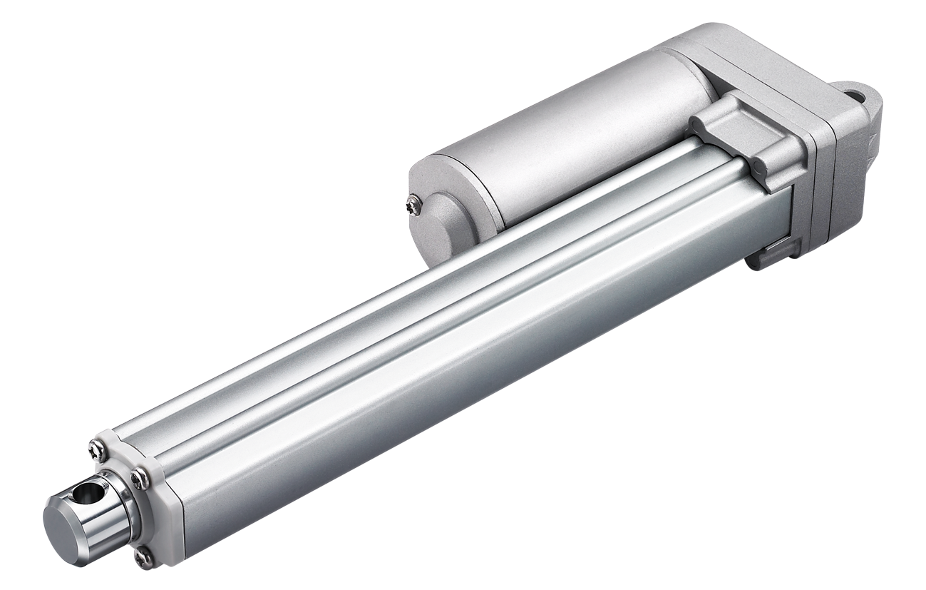
Product Segments Both the TA2 and the TA2P are compact, robust, and capable of performing
well in certain outdoor environments. A more powerful motor makes the TA2P
• Industrial Motion capable of handling load ratings up to 3500N (787 pounds) while retaining its
compact size. In addition to the high power motor, the TA2P linear actuator is
available with multiple choices for feedback sensors. Industry certifications for
the TA2P linear actuator include IEC / ES 60601-1 and UL73.
General Features
Max. load 3,500N (push)
2,000N (pull)
Max. speed at max. load 2.4mm/s
Max. speed at no load 56.5mm/s
Retracted length ≥ Stroke + 108mm
(with Hall sensors or without output signals)
IP rating IP66D
Certificate IEC60601-1, ES60601-1, EN 61000-6-1,
EN 61000-6-3, UL73
Stroke 20~1000mm
Options POT, Reed or Hall sensors
Voltage 12/24/36V DC; 12/24V DC (PTC)
Color Silver
Operational temperature range -25°C ~ +65°C
Operational temperature range +5°C ~ +45°C
at full performance
1
Page2
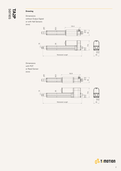
Drawing
Dimensions
without Output Signal
or with Hall Sensors
(mm)
124.4
22.5
Retracted Length 45
Dimensions
with POT
or Reed Sensor
(mm)
153.9
22.5
Retracted Length 45
2
15 15
ø20 ø20
35 33.3 35 33.3
20.9 22.5 20.9 22.5
77.4 45 77.4 45
TA2P
series
Page3
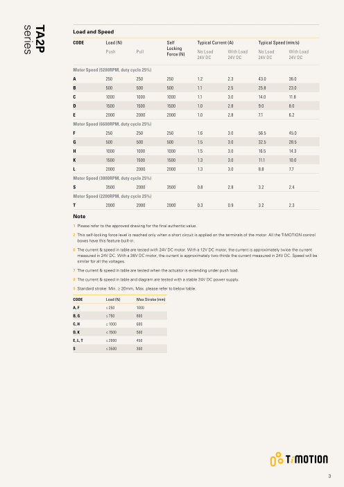
Load and Speed
CODE Load (N) Self Typical Current (A) Typical Speed (mm/s)
Locking
Push Pull Force (N) No Load With Load No Load With Load
24V DC 24V DC 24V DC 24V DC
Motor Speed (5200RPM, duty cycle 25%)
A 250 250 250 1.2 2.3 43.0 36.0
B 500 500 500 1.1 2.5 25.8 23.0
C 1000 1000 1000 1.1 3.0 14.0 11.8
D 1500 1500 1500 1.0 2.8 9.0 8.0
E 2000 2000 2000 1.0 2.8 7.1 6.2
Motor Speed (6600RPM, duty cycle 25%)
F 250 250 250 1.6 3.0 56.5 45.0
G 500 500 500 1.5 3.0 32.5 28.5
H 1000 1000 1000 1.5 3.0 16.5 14.3
K 1500 1500 1500 1.3 3.0 11.1 10.0
L 2000 2000 2000 1.3 3.0 8.8 7.7
Motor Speed (3800RPM, duty cycle 25%)
S 3500 2000 3500 0.8 2.8 3.2 2.4
Motor Speed (2200RPM, duty cycle 25%)
T 2000 2000 2000 0.3 0.9 3.2 2.3
Note
1 Please refer to the approved drawing for the final authentic value.
2 T his self-locking force level is reached only when a short circuit is applied on the terminals of the motor. All the TiMOTION control
boxes have this feature built-in.
6 The current & speed in table are tested with 24V DC motor. With a 12V DC motor, the current is approximately twice the current
measured in 24V DC. With a 36V DC motor, the current is approximately two-thirds the current measured in 24V DC. Speed will be
similar for all the voltages.
7 The current & speed in table are tested when the actuator is extending under push load.
8 T he current & speed in table and diagram are tested with a stable 24V DC power supply.
9 Standard stroke: Min. ≥ 20mm, Max. please refer to below table.
CODE Load (N) Max Stroke (mm)
A, F ≤ 250 1000
B, G ≤ 750 800
C, H ≤ 1000 600
D, K ≤ 1500 500
E, L, T ≤ 2000 450
S ≤ 3500 300
3
TA2P
series
Page4
Performance Data (24V DC)
Motor Speed (5200RPM, duty cycle 25%)
Speed vs. Load
60.0
50.0
40.0
A
30.0
B
20.0
C
10.0 D
E
0.0
0 1000 2000 3000 4000
Load (N)
Current vs. Load
6.0
5.0
4.0
C
3.0 D E
B
A
2.0
1.0
0.0
0 1000 2000 3000 4000
Load (N)
Note
1 The performance data in the curve charts shows theoretical value.
4
Current (A) Speed (mm/s)
TA2P
series
Page5
Performance Data (24V DC)
Motor Speed (6600RPM, duty cycle 25%)
Speed vs. Load
60.0
50.0
F
40.0
30.0 G
20.0
H
10.0 K
L
0.0
0 1000 2000 3000 4000
Load (N)
Current vs. Load
6.0
5.0
4.0
F G H K L
3.0
2.0
1.0
0.0
0 1000 2000 3000 4000
Load (N)
Note
1 T he performance data in the curve charts shows theoretical value.
5
Current (A) Speed (mm/s)
TA2P
series
Page6
Performance Data (24V DC)
Motor Speed (3800RPM, duty cycle 25%)
Speed vs. Load
60.0
50.0
40.0
30.0
20.0
10.0
S
0.0
0 1000 2000 3000 4000
Load (N)
Current vs. Load
6.0
5.0
4.0
3.0 S
2.0
1.0
0.0
0 1000 2000 3000 4000
Load (N)
Note
1 The performance data in the curve charts shows theoretical value.
6
Current (A) Speed (mm/s)
TA2P
series
Page7
Performance Data (24V DC)
Motor Speed (2200RPM, duty cycle 25%)
Speed vs. Load
60.0
50.0
40.0
30.0
20.0
10.0
T
0.0
0 1000 2000 3000 4000 5000 6000
Load (N)
Current vs. Load
6.0
5.0
4.0
3.0
2.0
1.0 T
0.0
0 1000 2000 3000 4000 5000 6000
Load (N)
Note
1 The performance data in the curve charts shows theoretical value.
7
Current (A) Speed (mm/s)
TA2P
series
Page8
TA2P Ordering Key
TA2P
Version: 20200717-P
Voltage 1 = 12V DC 5 = 24V DC, PTC, See page 10
2 = 24V DC 6 = 12V DC, PTC, See page 10
3 = 36V DC
Load and Speed See page 3
Stroke (mm) See page 3
Retracted Length See page 9
(mm)
Rear Attachment 1 = A luminum casting, hole 6.4, one piece casting with 4 = Aluminum casting, U clevis, slot 6.0, depth 10.5, hole
(mm) gear box 6.4, one piece casting with gear box
See page 10 2 = Aluminum casting, hole 8.0, one piece casting with 5 = Aluminum casting, U clevis, slot 6.0, depth 10.5, hole
gear box 8.0, one piece casting with gear box
3 = Aluminum casting, hole 10.0, one piece casting with 6 = Aluminum casting, U clevis, slot 6.0, depth 10.5, hole
gear box 10.0, one piece casting with gear box
Front Attachment 1 = A luminum casting, hole 6.4 4 = Aluminum CNC, U clevis, slot 6.0, depth 16.0, hole
(mm) 2 = Aluminum casting, hole 8.0 6.4
See page 11 3 = Aluminum CNC, U clevis, slot 6.0, depth 16.0, hole 5 = Aluminum CNC, U clevis, slot 6.0, depth 16.0, hole
10.0 8.0
Direction of 1 = 90° 2 = 0°
Rear Attachment
(Counterclockwise)
See page 11
Functions for 1 = Two switches at full retracted / extended positions to cut current
Limit Switches 2 = Two switches at full retracted / extended positions to cut current + third one in between to send signal
See page 11 3 = Two switches at full retracted / extended positions to send signal
4 = Two switches at full retracted / extended positions to send signal + third one in between to send signal
Output Signals 0 = Without 1 = POT 3 = Reed sensor 5 = Hall sensor * 2
Connector 1 = DIN 6P, 90° plug 2 = Tinned leads
See page 12
Cable Length (mm) 1 = Straight, 300 2 = Straight, 600 3 = Straight, 1000
IP Rating 1 = Without 2 = IP54 3 = IP66 6 = IP66D
8
Page9
TA2P Ordering Key Appendix
Retracted Length (mm)
1. Calculate A+B+C = Y
2. Retracted length needs to ≥ Stroke + Y
A. Attachment C. Output Signals
Front Rear Attachment CODE
Attachment
1, 2, 3 4, 5, 6 0, 5 -
1, 2 +108 +112 1, 3 +30
3, 4, 5 +120 +124
B. Load V.S. Stroke
Stroke (mm) Load (N)
< 3500 = 3500
20~150 - +5
151~200 +2 +7
201~250 +2 +7
251~300 +2 +7
301~350 +12 +17
351~400 +22 +27
401~450 +32 +37
451~500 +42 +47
501~550 +52 +57
551~600 +62 +67
601~650 +72 +77
651~700 +82 +87
701~750 +92 +97
751~800 +102 +107
801~850 +112 +117
851~900 +122 +127
901~950 +132 +137
951~1000 +142 +147
9
Page10
TA2P Ordering Key Appendix
Voltage
5 = 24V DC, PTC 6 = 12V DC, PTC
PTC PTC
100 100
min 250 min 250
Rear Attachment (mm)
1 = Aluminum casting, hole 6.4, one 2 = A luminum casting, hole 8.0, one 3 = Aluminum casting, hole 10.0, one 4 = Aluminum casting, U clevis, slot
piece casting with gear box piece casting with gear box piece casting with gear box 6.0, depth 10.5, hole 6.4, one
piece casting with gear box
11 11 11 15
R9.4 R9.4 R9.4 R11
ø6.4 ø8 ø10 ø6.4
10.5
5 = Aluminum casting, U clevis, slot 6 = Aluminum casting, U clevis, slot
6.0, depth 10.5, hole 8.0, one 6.0, depth 10.5, hole 10.0, one
piece casting with gear box piece casting with gear box
15 15
R11 R11
ø8 ø10
10.5 10.5
10
6
20
22
6
20
22
20
6
22
Page11
TA2P Ordering Key Appendix
Front Attachment (mm)
1 = A luminum casting, hole 6.4 2 = A luminum casting, hole 8.0 3 = Aluminum CNC, U clevis, slot 6.0, 4 = Aluminum CNC, U clevis, slot 6.0,
depth 16.0, hole 10.0 depth 16.0, hole 6.4
ø6.4 ø8 ø10 ø6.4
9 9
16 16
5 = A luminum CNC, U clevis, slot 6.0,
depth 16.0, hole 8.0
ø8
16
Direction of Rear Attachment (Counterclockwise)
1 = 90° 2 = 0°
Functions for Limit Switches
Wire Definitions
CODE Pin
1 (Green) 2 (Red) 3 (White) 4 (Black) 5 (Yellow) 6 (Blue)
1 extend (VDC+) N/A N/A N/A retract (VDC+) N/A
2 extend (VDC+) N/A middle switch pin B middle switch pin A retract (VDC+) N/A
3 extend (VDC+) common upper limit switch N/A retract (VDC+) lower limit switch
4 extend (VDC+) common upper limit switch medium limit switch retract (VDC+) lower limit switch
11
ø20
6
ø20
ø20
ø20
6
ø20
6
Page12
TA2P Ordering Key Appendix
Connector
1 = DIN 6P, 90° plug 2 = Tinned leads
4
50
Terms of Use
The user is responsible for determining the suitability of TiMOTION products for a specific application.
TiMOTION products are subject to change without prior notice.
12