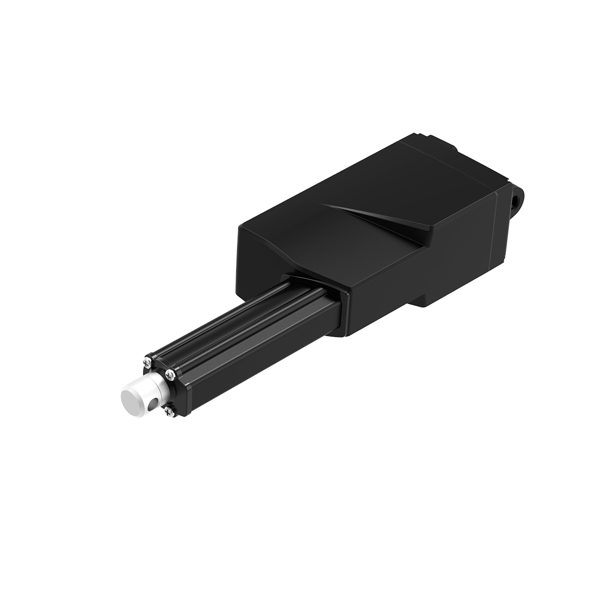


TiMOTIONのMA5リニアアクチュエータは過酷な作業環境向けに特別に設計され、IP69Kの保護は高圧ウォータージェット、および塵埃、その他の固体汚染物の侵入に耐えることができます。
MA5は、アプリケーションの要件に応じてさまざまなフィードバックオプションでカスタマイズすることもできます。 さらに、グリースニットを装備し、保護度合い寿命を向上させることができます。 MA5の適切なアプリケーションには、スプレッダー、ハーベスター、穀物ハンドラーなどの農業機器が含まれます。
【主な特長】
最大負荷:3,500N(Push)、2,000N(Pull)
速度(定格負荷時):45mm/sec(1,000N仕様)
ストローク:≥20〜1000mm
取付寸法:≥200mm
IP等級:最高IP69K
使用温度範囲:-25˚C〜+65˚C
フルパフォーマンスでの使用温度範囲:+ 5°C〜+ 45°C
オプション:ホールセンサー、POT、グリースチャンバー
このカタログについて
| ドキュメント名 | 電動リニアアクチュエータ【MA5】 |
|---|---|
| ドキュメント種別 | 製品カタログ |
| ファイルサイズ | 917.3Kb |
| 登録カテゴリ | |
| 取り扱い企業 | TiMotion Japan株式会社 (この企業の取り扱いカタログ一覧) |
この企業の関連カタログ


このカタログの内容
Page1
MA5
series
Product Segments TiMOTION’s MA5 linear actuator is specifically designed for applications which
face harsh working environments and require ruggedness and durability. Its
• Industrial Motion IP69K protection can withstand high pressure water jets, and the ingress of
dust and other solid contaminants.
The MA5 can also be customized with various feedback options depending
on the application requirements; moreover, it can be equipped with a grease
nipple to increase the protection degree and life cycle. Suitable applications for
MA5 include agricultural equipment, such as spreaders, harvesters, and grain
handlers.
General Features
Maximum load 3,500N in push
Maximum load 2,000N in pull
Maximum speed at full load 45mm/s
(with 250N in a push or pull condition)
Stroke ≥20~1000mm
Minimum installation dimension ≥200mm (upon the front attachment)
IP rating Up to IP69K
Operational temperature range -25˚C ~ +65˚C
Operational temperature range +5°C~+45°C
at full performance
Options Hall sensors, POT, grease chamber
1
Page2
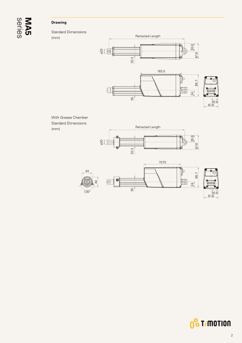
Drawing
Standard Dimensions
(mm) Retracted Length
163.5
30.8
61.6
With Grease Chamber
Standard Dimensions
(mm) Retracted Length
157.5
44
135° 30.8
61.6
2
44
ø20 ø20
35 33.3 35 33.3
24 30.8 24 30.8
85.7 61.6 85.7 61.6
MA5
series
Page3
Load and Speed
CODE Load (N) Self Locking Typical Current (A) Typical Speed (mm/s)
Force (N)
Push Pull No Load With Load No Load With Load
24V DC 24V DC 24V DC 24V DC
Motor Speed (5200RPM, duty cycle 25%)
A 250 250 250 1.2 2.3 43.0 36.0
B 500 500 500 1.1 2.3 25.8 23.0
C 1000 1000 1000 1.1 2.3 14.0 11.8
D 1500 1500 1500 1.0 2.2 9.0 8.0
E 2000 2000 2000 1.0 2.2 7.1 6.2
W 500 500 500 1.3 5.0 54.0 35.0
Motor Speed (6600RPM, duty cycle 25%)
F 250 250 250 1.6 2.8 56.5 45.0
G 500 500 500 1.5 2.8 32.5 28.5
H 1000 1000 1000 1.5 2.8 16.5 14.3
K 1500 1500 1500 1.3 2.8 11.1 10.0
L 2000 2000 2000 1.3 2.8 8.8 7.7
Motor Speed (3800RPM, duty cycle 25%)
S 3500 2000 3500 0.9 2.8 3.2 2.4
Motor Speed (2200RPM, duty cycle 25%)
T 2000 2000 2000 0.3 1.2 3.2 2.4
Note
1 Please refer to the approved drawing for the final authentic value.
2 This self-locking force level is reached only when a short circuit is applied on the terminals of the motor. All the TiMOTION control
boxes have this feature built-in.
3 T he current & speed in table are tested with 24V DC motor. With a 12V DC motor, the current is approximately twice the current
measured in 24V DC; speed will be similar for both voltages.
4 The current & speed in table are tested when the actuator is extending under push load.
5 The current & speed in table and diagram are tested with TiMOTION control boxes, and there will be around 10% tolerance
depending on different models of the control box. (Under no load condition, the voltage is around 32V DC. At rated load, the voltage
output will be around 24V DC)
6 Standard stroke: Min. ≥ 20mm, Max. please refer to below table.
CODE Load (N) Max Stroke (mm) CODE Load (N) Max Stroke (mm)
A, F ≦ 250 1000 D, K ≦ 1500 500
B, G, W ≦ 750 800 E, L, T ≦ 2000 450
C, H ≦ 1000 600 S ≦ 3500 300
3
MA5
series
Page4
Performance Data (24V DC Motor)
Motor Speed (5200RPM)
Speed vs. Load
50.0
40.0
A W
30.0
B
20.0
C
10.0 D
E
0.0
0 1000 2000 3000 4000 5000
Load (N)
Current vs. Load
W
5.0
4.0
3.0
A B C D E
2.0
1.0
0.0
0 1000 2000 3000 4000 5000
Load (N)
Note
1 The performance data in the curve charts shows theoretical value.
4
Current (A) Speed (mm/s)
MA5
series
Page5
Performance Data (24V DC Motor)
Motor Speed (6600RPM)
Speed vs. Load
50.0
F
40.0
30.0 G
20.0
H
K
10.0 L
0.0
0 1000 2000 3000 4000 5000
Load (N)
Current vs. Load
5.0
4.0
3.0 F G H K L
2.0
1.0
0.0
0 1000 2000 3000 4000 5000
Load (N)
Note
1 The performance data in the curve charts shows theoretical value.
5
Current (A) Speed (mm/s)
MA5
series
Page6
Performance Data (24V DC Motor)
Motor Speed (3800RPM)
Speed vs. Load
5.0
4.0
3.0
S
2.0
1.0
0.0
0 1000 2000 3000 4000 5000
Load (N)
Current vs. Load
5.0
4.0
3.0 S
2.0
1.0
0.0
0 1000 2000 3000 4000 5000
Load (N)
Note
1 The performance data in the curve charts shows theoretical value.
6
Current (A) Speed (mm/s)
MA5
series
Page7
Performance Data (24V DC Motor)
Motor Speed (2200RPM)
Speed vs. Load
5.0
4.0
3.0
T
2.0
1.0
0.0
0 1000 2000 3000 4000 5000
Load (N)
Current vs. Load
5.0
4.0
3.0
2.0
T
1.0
0.0
0 1000 2000 3000 4000 5000
Load (N)
Note
1 The performance data in the curve charts shows theoretical value.
7
Current (A) Speed (mm/s)
MA5
series
Page8
MA5 Ordering Key
MA5
Version: 20190327-E
Voltage 1 = 12V DC 2 = 24V DC 5 = 24V DC, PTC 6 = 12V DC, PTC
Load and Speed See page 3
Stroke (mm)
Retracted Length See page 9
(mm)
Rear Attachment 4 = A luminum casting, U clevis, slot 6.0, width 10.5, hole 6 = Aluminum casting, U clevis, slot 6.0, width 10.5, hole
(mm) 6.4, one piece casting with gear box 10.1, one piece casting with gear box
See page 10 5 = Aluminum casting, U clevis, slot 6.0, width 10.5, hole
8.0, one piece casting with gear box
Front Attachment 1 = Aluminum casting, hole 6.4 4 = Aluminum CNC, U clevis, slot 6.0, depth 16.0, hole
(mm) 2 = Aluminum casting, hole 8.0 6.4
See page 10 3 = A luminum CNC, U clevis, slot 6.0, depth 16.0, hole 5 = Aluminum CNC, U clevis, slot 6.0, depth 16.0, hole
10.0 8.0
Direction of 1 = 90° 2 = 0°
Rear Attachment
(Counterclockwise)
See page 10
Functions for 1 = Two switches at full retracted / extended positions to cut current
Limit Switches 2 = Two switches at full retracted / extended positions to cut current + third one in between to send signal
See page 11 3 = Two switches at full retracted / extended positions to send signal
4 = Two switches at full retracted / extended positions to send signal + third one in between to send signal
Output Signals 0 = Without 1 = POT 5 = Hall sensor*2
Connector 1 = DIN 6P, 90° plug 2 = Tinned leads
See page 11
Cable Length (mm) 1 = Straight, 300 2 = Straight, 600 3 = Straight, 1000
IP Rating 6 = IP66D 9 = IP69K
Wiper Set & 0 = Normal wiper, without grease chamber
Grease Nipple 1 = Enhanced wiper set, with grease chamber, grease nipple*1
2 = Enhanced wiper set, with grease chamber, grease nipple*2
3 = Enhanced wiper set, with grease chamber, without grease nipple
8
Page9
MA5 Ordering Key Appendix
Retracted Length (mm)
1. Calculate A+B+C = Y
2. Retracted length needs to ≥ Stroke + Y
3. The total Retacted length calculated must be equal or longer than below minimum value
(1) When choosing the wiper set #0: And the front attachment is #1, #2, min retracted length ≥ 200mm, And the front attachment
is #3, #4, #5, min retracted length ≥ 212mm
(2) When choosing the wiper set #1, #2, #3: And the front attachment is #1, #2min retracted length ≥ 238mm, And the
front attachment is #3, #4, #5min retracted length ≥ 250mm
A. Front Attachment C. Ouput Signals
1, 2 +112 0, 5 -
3, 4, 5 +124 1 +30
B. Load V.S. Stroke D. Wiper Set & Grease Nipple
Stroke (mm) Load (N) 0 -
< 3500 = 3500 1, 2, 3 +10
20 ~150 - +5
151~200 +2 +7
201~250 +2 +7
251~300 +2 +7
301~350 +12 +17
351~400 +22 +27
401~450 +32 +37
451~500 +42 +47
501~550 +52 +57
551~600 +62 +67
601~650 +72 +77
651~700 +82 +87
701~750 +92 +97
751~800 +102 +107
801~850 +112 +117
851~900 +122 +127
901~950 +132 +137
951~1000 +142 +147
9
Page10
MA5 Ordering Key Appendix
Rear Attachment (mm)
4 = A luminum casting, U clevis, slot 5 = Aluminum casting, U clevis, slot 6 = Aluminum casting, U clevis, slot
6.0, width 10.5, hole 6.4, one 6.0, width 10.5, hole 8.0, one 6.0, width 10.5, hole 10.1, one
piece casting with gear box piece casting with gear box piece casting with gear box
15 15 15
R11 R11 R11
ø6.4 ø8 ø10.1
10.5 10.5 10.5
Front Attachment (mm)
1 = Aluminum casting, hole 6.4 2 = Aluminum casting, hole 8.0 3 = Aluminum CNC, U clevis, slot 6.0, 4 = Aluminum CNC, U clevis, slot 6.0,
depth 16.0, hole 10.0 depth 16.0, hole 6.4
ø6.4 ø8 ø10 ø6.4
9 9
16 16
5 = A luminum CNC, U clevis, slot 6.0,
depth 16.0, hole 8.0
ø8
16
Direction of Rear Attachment (Counterclockwise)
1 = 90° 2 = 0°
10
ø20
6
ø20
6
22
ø20
6
22
ø20
6
6
22
ø20
6
Page11
MA5 Ordering Key Appendix
Functions for Limit Switches
Wire Definitions
CODE Pin
1 (Green) 2 (Red) 3 (White) 4 (Black) 5 (Yellow) 6 (Blue)
1 extend (VDC+) N/A N/A N/A retract (VDC+) N/A
2 extend (VDC+) N/A middle switch pin B middle switch pin A retract (VDC+) N/A
3 extend (VDC+) common upper limit switch N/A retract (VDC+) lower limit switch
4 extend (VDC+) common upper limit switch medium limit switch retract (VDC+) lower limit switch
Connector
1 = DIN 6P, 90° plug 2 = Tinned leads
4
50
Terms of Use
The user is responsible for determining the suitability of TiMOTION products for a specific application.
TiMOTION products are subject to change without prior notice.
11