


MGBが進化し、さらにユーザーフレンドリーに
マルチファンクションゲートボックスMGBは様々な産業の製造現場で多くの実績がございます。そのMGBが更に進化し、MGB2がラインナップに加わりました。従来、非常停止ボタンや照光式押しボタン、セレクタースイッチ等はMGB本体の型式ごとで搭載種や搭載数が固定されていましたが、MGB2はそれらコマンドファンクションはカードリッジ化されています。設備の変更の場合、機器そのもののの交換をせずとも、更新後の要求仕様に合わせてカードリッジを変更するだけで対応が可能です。この仕組みは保守面においてもメリットが得られます。
MGB2はMGBと同様、ProfiNetを用いることで省配線、省工数に大きく貢献します。多くのコマンドファンクションを必要とせず、ハードワイヤーでも対応可能なアプリケーションにおいてはMGB2 Clasiccが最適です。
カタログでは現在のMGB2のラインナップをご確認いただけます(現在、日本語版カタログは準備されておりません。英字版でのご確認となりますことご容赦ください)。
関連メディア
このカタログについて
| ドキュメント名 | マルチファンクションゲートボックス MGB2 |
|---|---|
| ドキュメント種別 | 製品カタログ |
| ファイルサイズ | 21.1Mb |
| 登録カテゴリ | |
| 取り扱い企業 | オイヒナー株式会社 (この企業の取り扱いカタログ一覧) |
この企業の関連カタログ


このカタログの内容
Page1
EN DE
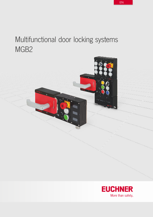
Multifunctional door locking systems
MGB2
Page2
Internationally successful – the EUCHNER company
EUCHNER GmbH + Co. KG is a world-leading company in the area of industrial safety
technology. EUCHNER has been developing and producing high-quality switching sys-
tems for mechanical and systems engineering for more than 60 years.
The medium-sized family-operated company based in Leinfelden, Germany, employs
Headquarters in Leinfelden-Echterdingen around 800 people around the world.
18 subsidiaries and other sales partners in Germany and abroad work for our inter-
national success on the market.
Quality and innovation – the EUCHNER products
A look into the past shows EUCHNER to be a company with a great inventive spirit.
We take the technological and ecological challenges of the future as an incentive for
Logistics center in Leinfelden-Echterdingen
extraordinary product developments.
EUCHNER safety switches monitor safety doors on machines and installations, help to
minimize dangers and risks and thereby reliably protect people and processes. Today,
our products range from electromechanical and electronic components to intelligent
integrated safety solutions. Safety for people, machines and products is one of our
dominant themes.
We defi ne future safety technology with the highest quality standards and reliable
Production location in Unterböhringen technology. Extraordinary solutions ensure the great satisfaction of our customers.
The product ranges are subdivided as follows:
Transponder-coded Safety Switches
Transponder-coded Safety Switches with guard locking
Multifunctional Gate Box MGB
Access management systems (Electronic-Key-System EKS)
Electromechanical Safety Switches
Magnetically coded Safety Switches
Enabling Switches
Safety Relays
Emergency Stop Devices
Hand-Held Pendant Stations and Handwheels
Safety Switches with AS-Interface
made Joystick Switches
in Position Switches
Germany
2
U2_U3_EN_2019.indd 1 27.05.19 09:55
Page3
Multifunctional door locking systems
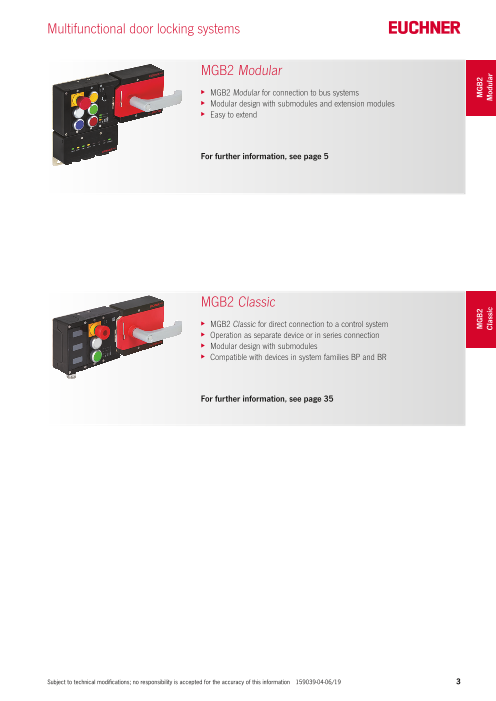
MGB2 Modular
XXMGB2 Modular for connection to bus systems
XXModular design with submodules and extension modules
XXEasy to extend
For further information, see page 5
MGB2 Classic
XXMGB2 Classic for direct connection to a control system
XXOperation as separate device or in series connection
XXModular design with submodules
XXCompatible with devices in system families BP and BR
For further information, see page 35
Subject to technical modifications; no responsibility is accepted for the accuracy of this information 159039‑04‑06/19 3
MGB2 MGB2
Classic Modular
Page4
4 Subject to technical modifications; no responsibility is accepted for the accuracy of this information 159039‑04‑06/19
Page5
Multifunctional Gate Box MGB2 Modular
General 6
The logical further development of the MGB – the MGB2 Modular 6
The new modularity – system components at a glance 7
Example for the combination of MGB2 and MBM 9
MGB2 Modular individual modules 10
Bus modules MBM 12
Locking modules MGB2-L.-… 16
Handle modules MGB2-H-… 18
Escape releases MGB-E-… 20
Extension modules MCM 22
Submodules MSM-1-… 24
MGB2 Modular sets 28
Accessories 60
Index 72
Subject to technical modifications; no responsibility is accepted for the accuracy of this information 159039‑04‑06/19 5
Sets MGB2
Modular Modular Modular
Page6
The logical further development of the
MGB – the MGB2 Modular
■ Modular design with submodules
■ Up to six MGB2 Modular on one bus module
■ Easy to extend
■ Submodule replacement in operation
■ For doors hinged on the right as well as on the left
■ Integrated alignment aid
MGB2 – the next generation MGB
The new MGB2 represents the logical further development of the globally protection. It makes it possible to integrate into one device all the relevant
successful Multifunctional Gate Box MGB. A revised design, new and functions related to the safety door. The MGB2 is suitable for both hinged
extended functions, as well as a modular layout offer maximum flexibility and sliding doors.
and cost-effectiveness. The MGB2 is more than just pure safety door
Straightforward connection concept – standard
cables suffice
In the Modular version, the MGB2 is connected to PROFINET/PROFIsafe Thanks to the modular design, the MGB2 Modular can be variably equipped
via a bus module MBM. This module can either be connected directly to the with different functions. The MGB2 Modular offers space for two submod-
MGB2 or, if space is tight, it can be mounted remotely. If the bus module ules, each with up to three different control elements.
is mounted remotely, as many as six MGB2 Modular can be connected The bus module MBM is available in two different versions; these two
to one MBM. The connection is made using standard M12 cables. You versions differ in the connection for PROFINET. An AIDA-compliant solution
can identify Modular devices with compatible connections based on the with RJ45 plug connectors and a solution with D-coded M12 connection
letters MLI in the item designation. They have a corresponding M12 mating are available. A common feature of both is the integrated PROFINET switch.
connector (MLI module plug connector, see example system on p. 15).
Several MGB2 Modular on one bus module MBM
Module connection Module connection
Proven technology enriched with innovations
Like its successful predecessor model, the MGB2 is equipped with a very All screws are equipped with the same Torx-T10 drive so that a single tool
robust, industrial housing and has an integrated metal door stop, as well is sufficient. These and many other minor improvements in the housing
as an integrated mounting plate. It can be mounted on doors hinged on the design ease mounting and the connection of the individual system
left and right, as well as on sliding doors. Changeover is performed during components.
mounting. The locking force of 2,000 N effectively prevents unintentional
opening of the guard. The MGB2 Modular meets the requirements of all
relevant standards, e.g. EN ISO 13849-1 and EN ISO 14119.
6 Subject to technical modifications; no responsibility is accepted for the accuracy of this information 159039‑04‑06/19
Page7
The new modularity – system
components at a glance
Bus module MBM – data collector and gateway Bus module MBM
With the bus module MBM, all EUCHNER Modular devices can be connect-
ed to a fieldbus system. The bus module has a direct connection for one
Modular device such that one MGB2 Modular or one MCM Modular can
be connected directly to a bus module (direct plug). If mounted remotely,
as an alternative several Modular devices can be connected using M12
cables (cable connected). The Modular connection technology makes it
possible to operate, e.g., up to 6 base units on one bus module MBM.
Different plug connector variants are available for connection to fieldbus
systems. A switch is integrated into Ethernet-based systems such that
series wiring both of the bus system and the power supply is possible.
Locking module MGB2 Modular – guard locking for Locking module MGB2 Modular
personnel and process protection
The MGB2 Modular locking module is available in different versions for
process protection guard locking or personnel protection guard locking. It
can be mounted on doors hinged on the left or right, and on sliding doors.
Together with a handle module, safety doors can be used as movable
guards with an interlocking device, with or without guard locking according
to EN ISO 14119.
There is space for up to two submodules MSM. In this way a very wide
range of control elements from emergency stops, through pushbuttons, to
key-operated rotary switches can be added such that a complete control
terminal can be created on the door. And if that is not enough, there is
the extension module MCM.
The MGB2 locking module is connected to an MBM bus module using an
M12 connection. This module collects all data and communicates with
the control system via a fieldbus.
Extension module MCM Modular – even more space Extension module MCM Modular
for functions
The extension module MCM can extend the functionality of the MGB2
considerably. If the maximum possible six control elements in the lock-
ing module MGB2 are not enough or labeling is required, four further
submodules MSM can be inserted into an extension module MCM.
The extension module MCM Modular can be connected either directly
to a bus module MBM or an MGB2 Modular. A 5-core M12 connecting
cable is also sufficient here. Alternatively, the extension module MCM
Modular can be docked directly to the MGB2 Modular as well as to the
bus module MBM. To be able to connect the MCM Modular to an MGB2
Modular, an additional plug is required for the module connection (see
accessories section).
Subject to technical modifications; no responsibility is accepted for the accuracy of this information 159039‑04‑06/19 7
Page8
Submodules MSM – a new concept for maximum Different submodules
variety
A large selection of different submodules MSM make the MGB2 into a small
control system. Different submodules are available to adapt the MGB2 or
the MCM optimally to the control functions necessary for a machine or
installation, whether for labeling or with pushbuttons, an emergency stop
or a connection for an enabling switch.
8 Subject to technical modifications; no responsibility is accepted for the accuracy of this information 159039‑04‑06/19
Page9
Example for the combination of
MGB2 and MBM
Submodule MSM Submodule MSM Handle module MGB2-H
3 pushbuttons with color covers emergency stop with protective collar with knob
127040 2 pushbuttons with color covers 157019
(see page 25) 126381 (see page 18)
(see page 25)
Locking module MGB2-L Modular
mechanically locked
136797
(see page 16)
Bus module MBM
with plug connector RJ45
156310
(see page 12)
Subject to technical modifications; no responsibility is accepted for the accuracy of this information 159039‑04‑06/19 9
Page10
MGB2 Modular
» Maximum flexibility – put
together your specific
MGB2 Modular.«
XXModular design with submodules
XXUp to six MGB2 Modular on one bus module
XXEasy to extend
XXSubmodule replacement in operation
XXFor doors hinged on the right as well as on the left
XXIntegrated alignment aid
XXCompatible with all Modular devices
10 Subject to technical modifications; no responsibility is accepted for the accuracy of this information 159039‑04‑06/19
Page11
MGB2 Modular
Bus module Locking module Handle module Escape release Extension module Submodules
MBM MGB2-L MGB2-H MGB-E MCM MSM
PN
Subject to technical modifications; no responsibility is accepted for the accuracy of this information 159039‑04‑06/19 11
Modular
Page12
Bus Modules MBM
Bus modules MBM
❚❚Details Further information
PROFINET interface f Dimension drawings see p. 13
The bus module MBM is available with one of the f Accessories and spare parts see p. 60
following PROFINET connections: f For detailed information, enter the order
f Plug connector M12 D‑coded (7/8" plug and number for the product in the search box at
M12 plug, D‑coded) according to IEC 61076‑ www.euchner.com.
2‑101)
f P lug connector RJ45, AIDA‑compliant (push‑
pull plug according to IEC 61076‑3‑117,
f Interface to PROFINET/PROFIsafe variant 14)
f Integrated switch PROFINET switch
f Compatible with all Modular devices Linear topology network structure due to integrat‑
ed switch (supports MRP).
MLI connections (module plug connector)
An MGB2 Modular or an MCM Modular can be
connected directly to a bus module (direct plug).
Alternatively, the modules can be connected using
commercially available connecting cables M12,
5‑core (cable connect).
❚❚Ordering table
Version MLI connections Order no./item
PN 2 x MLI cable connect
or 156312
M12 1 x MLI direct plug
MBM‑PN‑S4‑MLI‑3B‑156312
PN 2 x MLI cable connect
or 156310
1 x MLI direct plug MBM‑PN‑S3‑MLI‑3B‑156310RJ45
12 Subject to technical modifications; no responsibility is accepted for the accuracy of this information 159039‑04‑06/19
Page13
MBM
❚❚Dimension drawing
25 15
155 100
A
A
B
B
A- A
12 max.
B-B
12 max.
25 15
155 100
A
A
B
B
Subject to technical modifications; no responsibility is accepted for the accuracy of this information 159039‑04‑06/19 13
93 93
52,5 52,5
25,6
4
6,3 6,3
75 75
Page14
Bus Modules MBM
❚❚Terminal assignment
Version with 7/8" and M12 plugs, D-coded
Pin Designation Connections Pin Designation
XF1.1 Transmit Data +TD XD1.1 N2 auxiliary voltage *0 V
XF1.2 Receive Data +RD M12 XD1.2 N1 operating voltage 0 V
XF1.3 Transmit Data ‑TD_N PN XD1.3 Function earth
XF1.4 Receive Data ‑RD_N XD1.4 L1 operating voltage DC 24 V
XD1.5 L2 auxiliary voltage* DC 24 V
female female female male * T he auxiliary voltage is not required for the MGB2
system
4 3 4 3 5 1 1 5
Pin Designation 2 1 2 1 4 2 2 4 Pin Designation
XF2.1 Transmit Data +TD 3 3 XD2.1 N2 auxiliary voltage *0 V
XF2.2 Receive Data +RD XD2.2 N1 operating voltage 0 V
XF2.3 Transmit Data ‑TD_N XF1 PN1 XF2 PN2 XD2 DC24V XD1 DC24V XD2.3 Function earth
XF2.4 Receive Data ‑RD_N XD2.4 L1 operating voltage DC 24 V
XD2.5 L2 auxiliary voltage* DC 24 V
* The auxiliary voltage is not required for the MGB2
system
Version with push-pull plugs
Pin Designation Connections Pin Designation
XF1.1 Receive Data RD+ XD1.1 L1 operating voltage DC 24 V
XF1.2 Receive Data RD RJ45 XD1.2 N1 operating voltage 0 V
XF1.3 Transmit Data TD+ PN XD1.3 L2 auxiliary voltage* DC 24 V
XF1.4 n.c. XD1.4 N2 auxiliary voltage* 0 V
XF1.5 n.c. XD1.5 Function earth
XF1.6 Transmit Data TD * The auxiliary voltage is not required for the MGB2
XF1.7 n.c. system
XF1 PN1 XF2 PN2 XD2 DC24V XD1 DC24V
XF1.8 n.c.
Pin Designation Pin Designation
XF2.1 Receive Data RD+ XD2.1 L1 operating voltage DC 24 V
XF2.2 Receive Data RD 1 8 1 8 5 4 3 2 1 5 4 3 2 1 XD2.2 N1 operating voltage 0 V
XF2.3 Transmit Data TD+ RJ45 XD2.3 L2 auxiliary voltage* DC 24 V
XF2.4 n.c. XD2.4 N2 auxiliary voltage* 0 V
XF2.5 n.c. XD2.5 Function earth
XF2.6 Transmit Data TD * The auxiliary voltage is not required for the MGB2
XF2.7 n.c. system
XF2.8 n.c.
14 Subject to technical modifications; no responsibility is accepted for the accuracy of this information 159039‑04‑06/19
Page15
MBM
❚❚Example for the combination of MGB2 Modular and MBM
next module next module
cable connect direct plug
157028 157025
(M12, 5-pin,
female)
156718 (blind plug)
MCM-... MGB2-L...
157024
M12, 5-pin,
female
direct plug cable connect
M12, 5-pin,
male
Subject to technical modifications; no responsibility is accepted for the accuracy of this information 159039‑04‑06/19 15
Page16
Locking Modules MGB2 Modular
Locking modules MGB2-L.-…
❚❚Details Further information
Guard locking types f Dimension drawings see p. 17
L1 Closed-circuit current principle f Accessories and spare parts see p. 60
Guard locking by spring force. f For detailed information, enter the order
Release by applying voltage to the number for the product in the search box at
guard locking solenoid. www.euchner.com.
L2 Open-circuit current principle
Guard locking by solenoid force.
Activation of the guard locking by
f Guard locking for protection of persons applying voltage to the guard locking
or processes solenoid.
f Two slots for submodules Door stop
f Door stop can be changed to right/left On the locking modules, the door stop can be
f Category 4/PL e for the evaluation of changed from right to left and vice versa at any
all safety functions time with little effort.
f Compatible with all Modular devices
❚❚Ordering table
Submodules
Version Plug connector Door stop Order no./item
Slot 1 Slot 2 (factory setting)
MGB2-L1
Closed‑circuit current
principle
1 x
MLI
157024
Right 136797
1 x MGB2‑L1‑MLI‑U‑YA4A4‑BA‑R‑136797
blanking cover
156718
126372 126372
STOP
1 x
MLI
157024
Right 156374
1 x MGB2‑L1‑MLI‑U‑YB1A1‑DA‑R‑156374
blanking cover
156718
137610 136687
– – – – 136776MGB2‑L1‑MLI‑U‑Y0000‑BJ‑136776
STOP
1 x
MLI
157024
Left 156377
1 x MGB2‑L1‑MLI‑U‑YB1A1‑DA‑L‑156377
blanking cover
156718
137610 136687
16 Subject to technical modifications; no responsibility is accepted for the accuracy of this information 159039‑04‑06/19
Page17
MGB2-L
Submodules
Version Plug connector Door stop
Slot 1 Slot 2 (factory setting)
Order no./item
MGB2-L2
Open‑circuit current principle
1 x
MLI
157024
Right 156835
1 x MGB2‑L2‑MLI‑U‑YA4A4‑BA‑R‑156835
blanking cover
156718
126372 126372
STOP
1 x
MLI
157024
Right 156379
1 x MGB2‑L2‑MLI‑U‑YB1A1‑DA‑R‑156379
blanking cover
156718
137610 136687
– – – – 156392MGB2‑L2‑MLI‑U‑Y0000‑BJ‑156392
STOP
1 x
MLI
157024
Left 156381
1 x MGB2‑L2‑MLI‑U‑YB1A1‑DA‑L‑156381
blanking cover
156718
137610 136687
❚❚Dimension drawing
155 25 15
A
A
M12x1
A- A
12 max.
Subject to technical modifications; no responsibility is accepted for the accuracy of this information 159039‑04‑06/19 17
10,3 114
52,5
25,6
6,3
92,5
Page18
Handle Modules MGB2
Handle modules MGB2-H-…
❚❚Details Door knob
As an alternative to the door handle, the handle
Bolt tongue module can also be equipped or retrofitted with
The bolt tongue is reliably detected by a transpon‑ a door knob.
der as soon as it is inserted into the evaluation
module. Lockable from the inside
Handle modules with this function can be returned
Lockout mechanism (automatically extend- to the closed position from inside the installation
ing and fold-out) using an escape release.
For cleaning and service on the machine, the
bolt tongue can be locked with max. 3 padlocks Important: The actuating direction is not ad‑
f Bolt tongue with transponder using the fold‑out lockout mechanism. In this way justable.
f Fold-out lockout mechanism the operation of the handle is prevented in the
f Second automatically extending Further informationlocked state.
lockout mechanism (optional) Additionally, the optional lockout mechanism that f Dimension drawings see p. 19
f Silver-colored door handle or door extends automatically on the actuation of the f Accessories and spare parts see p. 60
knob handle can be used for 3 more padlocks. f For detailed information, enter the order
number for the product in the search box at
Door handle www.euchner.com.
The MGB has a robust door handle that can be
rotated in 90° steps to suit all installations. The
actuating direction can be changed very easily
for doors hinged on the left or right.
❚❚Ordering table
Version Order no./item
Right 137617l l MGB2‑H‑BA1A1‑R‑137617
156396
l l Left MGB2‑H‑BA1A1‑L‑156396
Right 136691l l l MGB2‑H‑BA1A3‑R‑136691
l l l Left 156394MGB2‑H‑BA1A3‑L‑156394
157019
l l l Right MGB2‑H‑BA1A5‑R‑157019
l l l Left 157020MGB2‑H‑BA1A5‑L‑157020
157021
l l l l Right MGB2‑H‑BA1A8‑R‑157021
Left 157022l l l l MGB2‑H‑BA1A8‑L‑157022
18 Subject to technical modifications; no responsibility is accepted for the accuracy of this information 159039‑04‑06/19
Door handle
Door knob
Lockable
from the inside
Automatically
extending lockout
mechanism
Fold-out lockout
mechanism
Door stop
(factory setting)
Page19
MGB2-H
❚❚Dimension drawing
15 16,5 A
A
130 A- A
146
159 12 max.
A
min. 6
max. 10
A
37
15 16,5 A
A
130
145,35
A-A
12 max.
Subject to technical modifications; no responsibility is accepted for the accuracy of this information 159039‑04‑06/19 19
53 114
52,5 114
63
58
89,4
6,3
89,4
6,3
25,6 8 max.
21
30 25,6 8 max.
Page20
Escape Releases for MGB2
Escape releases MGB-E-…
❚❚Details Extended actuation axis
Optionally, a 250 mm (instead of 107 mm) long
Escape release actuation axis 106761 can be ordered for thick‑
The safety system MGB2 can be equipped with er doors or profiles > 40 mm. The axis can be
an escape release module. shortened to the required dimension.
The escape release enables people shut in to
open the locked door from the danger zone. It Further information
is only necessary to actuate the door handle. f Dimension drawings see p. 21
The actuating direction automatically adapts to f Accessories and spare parts see p. 60
the actuating direction of the handle module and f For detailed information, enter the order
f Red door handle or door knob does not need to be changed. number for the product in the search box at
f Extended actuation axis for thicker The actuation axis supplied is suitable for profiles www.euchner.com.
doors (available optionally) up to 40 mm.
❚❚Ordering table
Version Order no./item
100465
l MGB‑E‑A‑100465
117126
l MGB‑E‑A7‑117126
20 Subject to technical modifications; no responsibility is accepted for the accuracy of this information 159039‑04‑06/19
Door handle
Door knob