


使いやすいエア・アクチュエータの総合カタログ
割り出し機構をコンパクトにユニット化、シンプル構造で使いやすいエア・アクチュエータをご紹介しています。
MINIDEX、MINITABLEなどの各種製品の概要をはじめ、特長や寸法・仕様などを掲載しています。
【掲載内容】
■エアインデックス用途例
■MINIDEX F Series
■MINITABLE Series
■製品取扱い上の注意
※詳しくはPDF資料をご覧いただくか、お気軽にお問い合わせ下さい。
このカタログについて
| ドキュメント名 | エアインデックス「MDF&MTシリーズ」 |
|---|---|
| ドキュメント種別 | 製品カタログ |
| ファイルサイズ | 2.5Mb |
| 登録カテゴリ | |
| 取り扱い企業 | 加茂精工株式会社 (この企業の取り扱いカタログ一覧) |
この企業の関連カタログ


このカタログの内容
Page1
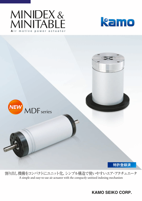
NEW MDFseries
特許登録済
割り出し機構をコンパクトにユニット化、シンプル構造で使いやすいエア・アクチュエータ
A simple and easy-to-use air actuator with the compactly unitized indexing mechanism
KAMO SEIKO CORP.
Page2
目次 Contents
無給油/Oilless 無給油/Oilless
MINIDEX F Series MINITABLE Series
● エアインデックスシリンダ MDF・・・・・・・・・P 4 ●エアインデックステーブル MT・・・・・・・・・・P10
Air Index Cylinder Air Index Table
製品取扱い上の注意
Precautions for handling ・・・・・・・・・・・・・・P15
Page3
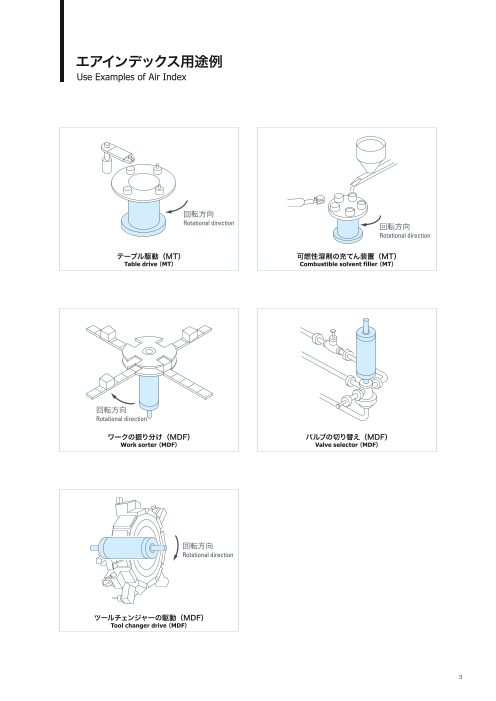
エアインデックス用途例
Use Examples of Air Index
回転方向
Rotational direction 回転方向
Rotational direction
テーブル駆動(MT) 可燃性溶剤の充てん装置(MT)
Table drive( MT) Combustible solvent filler( MT)
回転方向
Rotational direction
ワークの振り分け(MDF) バルブの切り替え(MDF)
Work sorter( MDF) Valve selector( MDF)
目次 Contents
無給油/Oilless 無給油/Oilless
MINIDEX F Series MINITABLE Series 回転方向
Rotational direction
● エアインデックスシリンダ MDF・・・・・・・・・P 4 ●エアインデックステーブル MT・・・・・・・・・・P10
Air Index Cylinder Air Index Table
製品取扱い上の注意
Precautions for handling ・・・・・・・・・・・・・・P15
ツールチェンジャーの駆動(MDF)
Tool changer drive( MDF)
Page4
MINIDEX ミニデックスは、非常に単純な要素により構成されています。これは、 MINIDEX is composed of very simple elements. This means that MINIDEX is highly
(Fシリーズ) 耐久性に優れ故障が少なく、また保守・安全性の良いことを示します。 durable with little trouble and highly maintainable and safe. The cams at both ends of the
カムピストン両端のカムにより、カムピストン片道で 1 割出を完了しま cam piston enable the completion of one indexing with one-way motion of the cam piston.
す。これにより、割出時間の高速化が可能になります。(従来比) This shortens the time required for indexing (compared with conventional types).
MDF20 MDF30
❶ ベアリングナット
Bearing nut
駆動部・割出機構をコンパクトにユニット化 ❷ 深溝玉軸受
❷ Deep groove ball bearing
❾
Wカム方式により高速・省エネ・高寿命を実現 ❸ ワンウェイクラッチ
(従来タイプ比較) ❺ One-way clutch
❽
❹ フォロアキャップ
Compactly unitized drive unit and indexing mechanism Follower cap
❻
Double-cam system has realized high speed, great energy-saving effect and long life O リング
(compared with conventional types). ❼ ❺
O-ring
❺ ❺ ❻ チューブ
Tube
❹
❸ カムピストン
❼
■ 型式表示 .. . . . . . . . . . . . . . . . . . . . . . . . . . . . . . . . . . . . . . . . . 4 ❷ Cam piston
❶
Model and type notation シャフト
❽
■ ミニデックスとは .. . . . . . . . . . . . . . . . . . . . . . . . . . . . . Shaft
5
What is MINIDEX ?
❾ カムキャップ
■ 動作原理 .. . . . . . . . . . . . . . . . . . . . . . . . . . . . . . . . . . . . . . . . . 5 Cam cap
Operating principle サークリップ
■ 外形寸法 .. . . . . . . . . . . . . . . . . . . . . . . . . . . . . . . . . . . . . . . . . 6 Circlip
Outside dimensions エアポート
■ 仕 様 .. . . . . . . . . . . . . . . . . . . . . . . . . . . . . . . . . . . . . . . . . . . . 7 Air port
Specifications ※ 図は MDF30 です。 ※ The above figure shows MDF30. エアポート
※ シール部分は全て JIS 規格品です。 ※ All seals are JIS-compliant.
■ 割出時間 .. . . . . . . . . . . . . . . . . . . . . . . . . . . . . . . . . . . . . . . . . 7 ※ 逆回転は内部のワンウェイクラッチ作用のためにできません。 ※ Air port
Inverse rotation is disabled by the action of the internal one-way clutch.
Indexing time
■ 割出トルク .. . . . . . . . . . . . . . . . . . . . . . . . . . . . . . . . . . . . . . . 8
Indexing torque
■ MDF選定計算手順 .. . . . . . . . . . . . . . . . . . . . . . . . . . . . 8 動作原理 Operating principle
Calculation procedure for MDF model selection
■ 配管方法 .. . . . . . . . . . . . . . . . . . . . . . . . . . . . . . . . . . . . . . . . . 9 内部ピストンが片道動くごとに 1 割出を完了します。 One-way motion of the internal piston completes one indexing.
Piping method
1. 割出完了(停止) Indexing completed (at a stop) 2. 割出中 Indexing in process 3. 割出完了(停止) Indexing completed (at a stop)
Air supply 給気 Air exhaust 排気
● エアシリンダ感覚での割出が可能 ● Indexing as if using an air cylinder シャフト カムキャップ カムピストン フォロアキャップ
Shaft Cam cap Cam piston Follower cap
● 一方向エンドレス回転 ● One-way endless rotation
● 両軸タイプの為、回転方向を選びません ● Double-shaft type to accept any rotational direction シャフト カムキャップ カムピストン フォロアキャップ シャフト カムキャップ カムピストン フォロアキャップ
Shaft Cam cap Cam piston Follower cap Shaft Cam cap Cam piston Follower cap
● 累積誤差ゼロ ● Zero accumulated error
● ワンウェイクラッチ内蔵により、シャフトの戻りは発生しません ● Built-in one-way clutch to prevent shaft return Air exhaust 排気 Air supply 給気
シャフト カムキャップ カムピストン フォロアキャップ
● 確実な割出停止構造により、オーバーランは発生しません ● Secure indexing stop mechanism to prevent overrun Shaft Cam cap Cam piston Follower cap
カムピストンとカムキャップが噛合っている状態です。 バルブ切替により、カムピストンが右(左)方向へ直動 カムピストンとフォロアキャップが完全に噛合い、1
します。カムキャップ(フォロアキャップ)との噛合い 割出を完了します。
が外れると、フォロアキャップ(カムキャップ)との噛
合いが始まりカムピストンが回転します。
カムピストンの回転はシャフトに伝達されます。
The cam piston and the cam cap are in engagement. When the solenoid valve is switched, the cam piston moves The cam piston and the follower cap become in complete
directly to the right (left). When the cam piston is disengaged from engagement, and complete one indexing.
型式表示 Model and type notation the cam cap (follower cap), the cam piston starts engagement with
the follower cap (cam cap), and rotates. The rotation of the cam
ご注文の際は、下記のようにご明記ください。 When placing an order, specify the model as follows. piston is transmitted to the shaft.
例)
MDF 型 番 割出数 MDF30-12 〈MDF30 の型番で 12 割出タイプ〉
ex.)
Model No. Number of divisions MDF30-12〈Model MDF30 with 12 divisions〉
仕様・詳細についてはホームページにてご確認ください。http://www.kamo.co.jp For the specifications and the details, refer to our website http://www.kamo.co.jp
Page5
MINIDEX ミニデックスは、非常に単純な要素により構成されています。これは、 MINIDEX is composed of very simple elements. This means that MINIDEX is highly
(Fシリーズ) 耐久性に優れ故障が少なく、また保守・安全性の良いことを示します。 durable with little trouble and highly maintainable and safe. The cams at both ends of the
カムピストン両端のカムにより、カムピストン片道で 1 割出を完了しま cam piston enable the completion of one indexing with one-way motion of the cam piston.
す。これにより、割出時間の高速化が可能になります。(従来比) This shortens the time required for indexing (compared with conventional types).
MDF20 MDF30
❶ ベアリングナット
Bearing nut
駆動部・割出機構をコンパクトにユニット化 ❷ 深溝玉軸受
❷ Deep groove ball bearing
❾
Wカム方式により高速・省エネ・高寿命を実現 ❸ ワンウェイクラッチ
(従来タイプ比較) ❺ One-way clutch
❽
❹ フォロアキャップ
Compactly unitized drive unit and indexing mechanism Follower cap
❻
Double-cam system has realized high speed, great energy-saving effect and long life O リング
(compared with conventional types). ❼ ❺
O-ring
❺ ❺ ❻ チューブ
Tube
❹
❸ カムピストン
❼
■ 型式表示 .. . . . . . . . . . . . . . . . . . . . . . . . . . . . . . . . . . . . . . . . . 4 ❷ Cam piston
❶
Model and type notation シャフト
❽
■ ミニデックスとは .. . . . . . . . . . . . . . . . . . . . . . . . . . . . . Shaft
5
What is MINIDEX ?
❾ カムキャップ
■ 動作原理 .. . . . . . . . . . . . . . . . . . . . . . . . . . . . . . . . . . . . . . . . . 5 Cam cap
Operating principle サークリップ
■ 外形寸法 .. . . . . . . . . . . . . . . . . . . . . . . . . . . . . . . . . . . . . . . . . 6 Circlip
Outside dimensions エアポート
■ 仕 様 .. . . . . . . . . . . . . . . . . . . . . . . . . . . . . . . . . . . . . . . . . . . . 7 Air port
Specifications ※ 図は MDF30 です。 ※ The above figure shows MDF30. エアポート
※ シール部分は全て JIS 規格品です。 ※ All seals are JIS-compliant.
■ 割出時間 .. . . . . . . . . . . . . . . . . . . . . . . . . . . . . . . . . . . . . . . . . 7 ※ 逆回転は内部のワンウェイクラッチ作用のためにできません。 ※ Air port
Inverse rotation is disabled by the action of the internal one-way clutch.
Indexing time
■ 割出トルク .. . . . . . . . . . . . . . . . . . . . . . . . . . . . . . . . . . . . . . . 8
Indexing torque
■ MDF選定計算手順 .. . . . . . . . . . . . . . . . . . . . . . . . . . . . 8 動作原理 Operating principle
Calculation procedure for MDF model selection
■ 配管方法 .. . . . . . . . . . . . . . . . . . . . . . . . . . . . . . . . . . . . . . . . . 9 内部ピストンが片道動くごとに 1 割出を完了します。 One-way motion of the internal piston completes one indexing.
Piping method
1. 割出完了(停止) Indexing completed (at a stop) 2. 割出中 Indexing in process 3. 割出完了(停止) Indexing completed (at a stop)
Air supply 給気 Air exhaust 排気
● エアシリンダ感覚での割出が可能 ● Indexing as if using an air cylinder シャフト カムキャップ カムピストン フォロアキャップ
Shaft Cam cap Cam piston Follower cap
● 一方向エンドレス回転 ● One-way endless rotation
● 両軸タイプの為、回転方向を選びません ● Double-shaft type to accept any rotational direction シャフト カムキャップ カムピストン フォロアキャップ シャフト カムキャップ カムピストン フォロアキャップ
Shaft Cam cap Cam piston Follower cap Shaft Cam cap Cam piston Follower cap
● 累積誤差ゼロ ● Zero accumulated error
● ワンウェイクラッチ内蔵により、シャフトの戻りは発生しません ● Built-in one-way clutch to prevent shaft return Air exhaust 排気 Air supply 給気
シャフト カムキャップ カムピストン フォロアキャップ
● 確実な割出停止構造により、オーバーランは発生しません ● Secure indexing stop mechanism to prevent overrun Shaft Cam cap Cam piston Follower cap
カムピストンとカムキャップが噛合っている状態です。 バルブ切替により、カムピストンが右(左)方向へ直動 カムピストンとフォロアキャップが完全に噛合い、1
します。カムキャップ(フォロアキャップ)との噛合い 割出を完了します。
が外れると、フォロアキャップ(カムキャップ)との噛
合いが始まりカムピストンが回転します。
カムピストンの回転はシャフトに伝達されます。
The cam piston and the cam cap are in engagement. When the solenoid valve is switched, the cam piston moves The cam piston and the follower cap become in complete
directly to the right (left). When the cam piston is disengaged from engagement, and complete one indexing.
型式表示 Model and type notation the cam cap (follower cap), the cam piston starts engagement with
the follower cap (cam cap), and rotates. The rotation of the cam
ご注文の際は、下記のようにご明記ください。 When placing an order, specify the model as follows. piston is transmitted to the shaft.
例)
MDF 型 番 割出数 MDF30-12 〈MDF30 の型番で 12 割出タイプ〉
ex.)
Model No. Number of divisions MDF30-12〈Model MDF30 with 12 divisions〉
仕様・詳細についてはホームページにてご確認ください。http://www.kamo.co.jp For the specifications and the details, refer to our website http://www.kamo.co.jp
Page6
■MDF20 型 式
Model MDF20 MDF30
割出数 4・6・8 4・6・8・10・12
Number of divisions
4×M4 深さ 10 4×M4 深さ 10 割出時間 ※1)
sec 0.1~ 0.1~
×M4 Depth 10 4×M4 Depth 10 Indexing time
l direction 4
ona 基準マーク 4×φ4.5 6 5 4×φ4.5
tati Reference mark 回
o 転方向 割出精度 ± arc・min
キー溝巾 3P9 深さ 1.8 +0.1 キー溝巾 3P9 深さ 1.8 +0.1 R
0 ( o
R tat sion ±30 ※3)
Indexing preci
io
Key depth width 3P9 depth 1.8 ) (R) 0
Key-way width 3P9 depth 1.8 n
許容慣性モーメント ×10-4kg・m2 12.5 25
Allowable inertia moment
割出トルク ※2)
N・m 0.13~1.3 0.3~3.5
Indexing torque
30 30 最高使用圧力 MPa
Max. working pressure 0.7
P1 ポート P2 ポート 最低使用圧力
P1 Port P2 Port MPa
2×M5 Min. working pressure 0.2
16 (35) 35 16
許容ラジアル荷重
(21) 4 (93) 4 (21) N 14.7 29.4
Allowable radial load
(143) 許容スラスト荷重 N 9.8 24.5
Allowable thrust load
質 量 kg 0.5 0.9
Mass weight
P1加圧 P2加圧 P1加圧 P2加圧
内部容積
Internal volume cm3
12 11 26 24
※1 割出時間は、負荷及び割出数によって異なります。詳しくは、下記グラフを参照してください。 ※1 The indexing time depends on the load and the number of divisions. For details, refer to the below graphs.
■MDF30 ※2 割出トルクは、使用圧力及び割出数によって異なります。詳しくは、下記グラフを参照してください。 ※2 The indexing torque depends on the working pressure and the number of divisions. For details, refer to the below graphs.
※3 仕様表以下の高精度品は、別途ご相談下さい。 ※3 For higher precision than the specifications, consult with us.
4×M5 深さ 12 4×M5 深さ 12
4×M5 Depth 12
7 7 4×M5 Depth 12
ion
l direct 基準マーク
iona 4×φ5.3 4×φ5.3
Reference mark 回転方向
Rotat
+0.1 + R
.5° キー溝巾 4P9 深さ 2.5 (R キー溝巾 4P9 深さ 2.5 0.1 ot
0 0 ation
Key depth width 4P9 depth 2.5 ) (R)
Key depth width 4P9 depth 2.5 a 割出時間 Indexing time
112
割出時間は、負荷に応じて下図のグラフより算出してください。
Calculate the indexing time according to the load by referring to the below graphs.
※ 1割出(内部ピストン片道時間)に要する時間を示します。
※ The indexing time shows the time required for one indexing (for the internal piston to make one-way motion).
2×Rc1/8 ※ グラフの線を超えた範囲での動作は、破損の原因となる為おやめ下さい。
P1 ポート P2 ポート MDFは、停止端にて衝撃が発生します。ワークのズレ等がある場合は、スピコン(メーターアウト)で速度の調整を行って下さい。
P1 Port P2 Port
16 (32) 58 16 ※ Do not operate beyond the range indicated by the graph lines, or break would be caused.
(21) 5 (112) 5 (21) An impact is caused at the stop end. If there is any resultant abnormality, such as work displacement, adjust the speed with the speed controller (in the meter-out circuit).
(164)
MDF20 MDF30
2
0-1 10
3 30
-
25
12.5
10 10
0-8 0-6 4 0-8 0-6 -4
2 2 20
-
3 3 30
5 5
1 1
0.1 0.1
0.1 0.5 1 0.1 0.5 1
割出時間 Indexing time sec 割出時間 Indexing time sec
回転方向 回転
157.5° 方向 R
φ50
φ37
φ28h7
φ22h7
φ10h7
φ8h7
φ8h7
φ22h7
φ10h7
φ37
φ28h7
φ50
40
慣性モーメント Inertia moment ×10-4kg・m2
慣性モーメント Inertia moment ×10-4kg・m2
tion
n irec
ctio l
d
dire
al
40
Page7
■MDF20 型 式
Model MDF20 MDF30
割出数 4・6・8 4・6・8・10・12
Number of divisions
4×M4 深さ 10 4×M4 深さ 10 割出時間 ※1)
sec 0.1~ 0.1~
×M4 Depth 10 4×M4 Depth 10 Indexing time
l direction 4
ona 基準マーク 4×φ4.5 6 5 4×φ4.5
tati Reference mark 回
o 転方向 割出精度 ± arc・min
キー溝巾 3P9 深さ 1.8 +0.1 キー溝巾 3P9 深さ 1.8 +0.1 R
0 ( o
R tat sion ±30 ※3)
Indexing preci
io
Key depth width 3P9 depth 1.8 ) (R) 0
Key-way width 3P9 depth 1.8 n
許容慣性モーメント ×10-4kg・m2 12.5 25
Allowable inertia moment
割出トルク ※2)
N・m 0.13~1.3 0.3~3.5
Indexing torque
30 30 最高使用圧力 MPa
Max. working pressure 0.7
P1 ポート P2 ポート 最低使用圧力
P1 Port P2 Port MPa
2×M5 Min. working pressure 0.2
16 (35) 35 16
許容ラジアル荷重
(21) 4 (93) 4 (21) N 14.7 29.4
Allowable radial load
(143) 許容スラスト荷重 N 9.8 24.5
Allowable thrust load
質 量 kg 0.5 0.9
Mass weight
P1加圧 P2加圧 P1加圧 P2加圧
内部容積
Internal volume cm3
12 11 26 24
※1 割出時間は、負荷及び割出数によって異なります。詳しくは、下記グラフを参照してください。 ※1 The indexing time depends on the load and the number of divisions. For details, refer to the below graphs.
■MDF30 ※2 割出トルクは、使用圧力及び割出数によって異なります。詳しくは、下記グラフを参照してください。 ※2 The indexing torque depends on the working pressure and the number of divisions. For details, refer to the below graphs.
※3 仕様表以下の高精度品は、別途ご相談下さい。 ※3 For higher precision than the specifications, consult with us.
4×M5 深さ 12 4×M5 深さ 12
4×M5 Depth 12
7 7 4×M5 Depth 12
ion
l direct 基準マーク
iona 4×φ5.3 4×φ5.3
Reference mark 回転方向
Rotat
+0.1 + R
.5° キー溝巾 4P9 深さ 2.5 (R キー溝巾 4P9 深さ 2.5 0.1 ot
0 0 ation
Key depth width 4P9 depth 2.5 ) (R)
Key depth width 4P9 depth 2.5 a 割出時間 Indexing time
112
割出時間は、負荷に応じて下図のグラフより算出してください。
Calculate the indexing time according to the load by referring to the below graphs.
※ 1割出(内部ピストン片道時間)に要する時間を示します。
※ The indexing time shows the time required for one indexing (for the internal piston to make one-way motion).
2×Rc1/8 ※ グラフの線を超えた範囲での動作は、破損の原因となる為おやめ下さい。
P1 ポート P2 ポート MDFは、停止端にて衝撃が発生します。ワークのズレ等がある場合は、スピコン(メーターアウト)で速度の調整を行って下さい。
P1 Port P2 Port
16 (32) 58 16 ※ Do not operate beyond the range indicated by the graph lines, or break would be caused.
(21) 5 (112) 5 (21) An impact is caused at the stop end. If there is any resultant abnormality, such as work displacement, adjust the speed with the speed controller (in the meter-out circuit).
(164)
MDF20 MDF30
2
0-1 10
3 30
-
25
12.5
10 10
0-8 0-6 4 0-8 0-6 -4
2 2 20
-
3 3 30
5 5
1 1
0.1 0.1
0.1 0.5 1 0.1 0.5 1
割出時間 Indexing time sec 割出時間 Indexing time sec
回転方向 回転
157.5° 方向 R
φ50
φ37
φ28h7
φ22h7
φ10h7
φ8h7
φ8h7
φ22h7
φ10h7
φ37
φ28h7
φ50
40
慣性モーメント Inertia moment ×10-4kg・m2
慣性モーメント Inertia moment ×10-4kg・m2
tion
n irec
ctio l
d
dire
al
40
Page8
割出トルク Indexing torque 配管方法 Piping method
トルク特性は割出数によって異なります。グラフを参照して選定下さい。 MDFは複動エアシリンダと同様に、本体側面のエアーポートにエアーを供給すれば1割出を行います。配管は下図を参考に行って下さい。
The torque characteristics depend on the number of divisions. Select the torque characteristics by referring to the below graphs. In the same way as double-acting cylinders, MDF performs one indexing when air is supplied to the air-intake port located in the side of the main body. For the piping diagram, refer to the following figure:
※ グラフの線を超えた範囲での動作は、破損の原因となる為おやめ下さい。 • エアポート2か所の流路切り替えには電磁弁を使用して下さい。
※ Do not operate beyond the range indicated by the graph lines, or break would be caused. • For flow channel switching for 2 intake ports, use a solenoid valve.
※ 抵抗負荷の場合、製品の割出トルクTと負荷トルクTaは以下の関係を持たせてください。 • 電磁弁は必ずダブルソレノイドを使用して下さい。
T≧Ta×n n:余裕率(2以上) (シングルソレノイドバルブの場合、非常停止時にピストン位置によっては、次の割出を行ってしまう事があります。)
※ For the resistance load, relate the product indexing torque T to the load torque Ta as follows: • For the solenoid valve, be sure to use a double solenoid valve.
T≧Ta×n n: Safety factor (≧2) (When a single solenoid type is used, the next indexing could be performed in an emergency case depending on the position of the piston.)
• 回転速度はスピコンで排気側を絞り、停止時に衝撃の無きよう調整して下さい。
MDF20 MDF30 • In adjusting the rotational speed, throttle the flow rate on the exhaust side with the speed controller to prevent any impact at the time of stopping.
1.4 4
3.5
1.2 スピコンはメータアウトを使用
Set the speed controller in the meter-out circuit.
3
1
2.5
0.8
2
0.6
1.5
4
30
-
0.4
1
SOL1 SOL2
0.2
0.5
最高使用圧力 0.7MPa
0 0 Max. working pressure: 0.7MPa
0.2 0.3 0.4 0.5 0.6 0.7 0.2 0.3 0.4 0.5 0.6 0.7 ※ 電磁弁 Solenoid valve
エア圧力 Air pressure MPa エア圧力 Air pressure MPa
MDF選定計算手順 Calculation procedure for MDF model selection
①使用条件の確認 ①Confirmation of operating conditions
●使用圧力の確認 ● Working pressure range
MDF の使用圧力範囲は 0.2 ~ 0.7MPa です。 The working pressure range of MDF is 0.2-0.7MPa.
●使用する割出数 ● Number of divisions
割出数は、仕様表 P.7 を参照ください。 For the number of divisions, refer to the specifications on P. 7.
● ※ 電磁弁は5ポート2位置ダブルソレノイドバルブ
Desired indexing time
●希望割出時間 The indexing time is set for each model. Do not operate faster than the set indexing time, or 又は、5ポート3位置ダブルソレノイドバルブ(プレッシャセンタ推奨)を使用
各型式で最小割出時間が設定されています。これより早い運転は早期破損の原 early break would be caused. For the solenoid valve, use a 5-port 2-position double solenoid valve or a 5-port 3-position double solenoid valve
因となるため、お止めください。 (pressure center is recommended).
②Confirmation of the load inertia moment
②負荷慣性モーメントの確認 Calculate the load inertial moment to be attached to MDF.
MDF に取付ける負荷の慣性モーメントを計算します。
③Confirmation of the applied load
③負荷荷重の確認 Calculate the radial load and thrust load externally acting on the shaft.
外部からシャフトに作用するラジアル荷重、スラスト荷重を計算します。 ④Selection of the model
Select the model that can satisfy both the ② load inertia moment and the ③ applied load.
④型式選定
②負荷慣性モーメント及び③負荷荷重を満足する型番を、選定してください。 ⑤Setting of the indexing time
Confirm the indexing time according to the inertia moment by referring to the indexing time graphs
⑤割出時間の設定 on P. 7.
割出時間のグラフP.7より、慣性モーメントに応じた割出時間を確認してください。 ※ The indexing time depends on the load and the number of divisions.
※割出時間は、負荷及び割出数により異なります。 ※ Do not operate beyond the range indicated by the graph lines, or break would be caused.
Since MDF has no reduction mechanism, an impact is caused at the stop end. When stopped, the
※割出時間グラフの線を超えた範囲での運転は破損の原因となります。 impact may affect the work, etc. on the table. To avoid this, provide a work displacement
※MDF に減速機構はありません。よって停止端では衝撃が発生します。停止の際、 preventing device or adjust the speed with the speed controller (in the meter-out circuit) according
テーブル上のワーク等に衝撃が伝わることがあります。その場合は、ワーク位置ず to the impact extent. This is not reflected in the indexing time set value in the specifications.
れ防止を設けるか、衝撃程度に応じてスピコン(メーターアウト)で速度の調整を
行って下さい。仕様表の割出時間は、上記を加味した設定にはなっておりません。 ⑥When torque acts due to external force, etc.
Confirm the torque value of the desired model by referring to the indexing torque graphs on P. 8.
⑥外力等でトルクが作用する場合 ※ The indexing torque depends on the working pressure and the number of divisions.
割出トルクのグラフ P.8 より、使用したい型番のトルク値を確認してください。
※割出トルクは、使用圧力及び割出数により異なります。
8 9
割出トルク Indexing torque N・m
20- 2 2
4 0-6 0-8
割出トルク Indexing torque N・m
30 3
- 0
6 -1 30
0 -12
30-8
Page9
割出トルク Indexing torque 配管方法 Piping method
トルク特性は割出数によって異なります。グラフを参照して選定下さい。 MDFは複動エアシリンダと同様に、本体側面のエアーポートにエアーを供給すれば1割出を行います。配管は下図を参考に行って下さい。
The torque characteristics depend on the number of divisions. Select the torque characteristics by referring to the below graphs. In the same way as double-acting cylinders, MDF performs one indexing when air is supplied to the air-intake port located in the side of the main body. For the piping diagram, refer to the following figure:
※ グラフの線を超えた範囲での動作は、破損の原因となる為おやめ下さい。 • エアポート2か所の流路切り替えには電磁弁を使用して下さい。
※ Do not operate beyond the range indicated by the graph lines, or break would be caused. • For flow channel switching for 2 intake ports, use a solenoid valve.
※ 抵抗負荷の場合、製品の割出トルクTと負荷トルクTaは以下の関係を持たせてください。 • 電磁弁は必ずダブルソレノイドを使用して下さい。
T≧Ta×n n:余裕率(2以上) (シングルソレノイドバルブの場合、非常停止時にピストン位置によっては、次の割出を行ってしまう事があります。)
※ For the resistance load, relate the product indexing torque T to the load torque Ta as follows: • For the solenoid valve, be sure to use a double solenoid valve.
T≧Ta×n n: Safety factor (≧2) (When a single solenoid type is used, the next indexing could be performed in an emergency case depending on the position of the piston.)
• 回転速度はスピコンで排気側を絞り、停止時に衝撃の無きよう調整して下さい。
MDF20 MDF30 • In adjusting the rotational speed, throttle the flow rate on the exhaust side with the speed controller to prevent any impact at the time of stopping.
1.4 4
3.5
1.2 スピコンはメータアウトを使用
Set the speed controller in the meter-out circuit.
3
1
2.5
0.8
2
0.6
1.5
4
30
-
0.4
1
SOL1 SOL2
0.2
0.5
最高使用圧力 0.7MPa
0 0 Max. working pressure: 0.7MPa
0.2 0.3 0.4 0.5 0.6 0.7 0.2 0.3 0.4 0.5 0.6 0.7 ※ 電磁弁 Solenoid valve
エア圧力 Air pressure MPa エア圧力 Air pressure MPa
MDF選定計算手順 Calculation procedure for MDF model selection
①使用条件の確認 ①Confirmation of operating conditions
●使用圧力の確認 ● Working pressure range
MDF の使用圧力範囲は 0.2 ~ 0.7MPa です。 The working pressure range of MDF is 0.2-0.7MPa.
●使用する割出数 ● Number of divisions
割出数は、仕様表 P.7 を参照ください。 For the number of divisions, refer to the specifications on P. 7.
● ※ 電磁弁は5ポート2位置ダブルソレノイドバルブ
Desired indexing time
●希望割出時間 The indexing time is set for each model. Do not operate faster than the set indexing time, or 又は、5ポート3位置ダブルソレノイドバルブ(プレッシャセンタ推奨)を使用
各型式で最小割出時間が設定されています。これより早い運転は早期破損の原 early break would be caused. For the solenoid valve, use a 5-port 2-position double solenoid valve or a 5-port 3-position double solenoid valve
因となるため、お止めください。 (pressure center is recommended).
②Confirmation of the load inertia moment
②負荷慣性モーメントの確認 Calculate the load inertial moment to be attached to MDF.
MDF に取付ける負荷の慣性モーメントを計算します。
③Confirmation of the applied load
③負荷荷重の確認 Calculate the radial load and thrust load externally acting on the shaft.
外部からシャフトに作用するラジアル荷重、スラスト荷重を計算します。 ④Selection of the model
Select the model that can satisfy both the ② load inertia moment and the ③ applied load.
④型式選定
②負荷慣性モーメント及び③負荷荷重を満足する型番を、選定してください。 ⑤Setting of the indexing time
Confirm the indexing time according to the inertia moment by referring to the indexing time graphs
⑤割出時間の設定 on P. 7.
割出時間のグラフP.7より、慣性モーメントに応じた割出時間を確認してください。 ※ The indexing time depends on the load and the number of divisions.
※割出時間は、負荷及び割出数により異なります。 ※ Do not operate beyond the range indicated by the graph lines, or break would be caused.
Since MDF has no reduction mechanism, an impact is caused at the stop end. When stopped, the
※割出時間グラフの線を超えた範囲での運転は破損の原因となります。 impact may affect the work, etc. on the table. To avoid this, provide a work displacement
※MDF に減速機構はありません。よって停止端では衝撃が発生します。停止の際、 preventing device or adjust the speed with the speed controller (in the meter-out circuit) according
テーブル上のワーク等に衝撃が伝わることがあります。その場合は、ワーク位置ず to the impact extent. This is not reflected in the indexing time set value in the specifications.
れ防止を設けるか、衝撃程度に応じてスピコン(メーターアウト)で速度の調整を
行って下さい。仕様表の割出時間は、上記を加味した設定にはなっておりません。 ⑥When torque acts due to external force, etc.
Confirm the torque value of the desired model by referring to the indexing torque graphs on P. 8.
⑥外力等でトルクが作用する場合 ※ The indexing torque depends on the working pressure and the number of divisions.
割出トルクのグラフ P.8 より、使用したい型番のトルク値を確認してください。
※割出トルクは、使用圧力及び割出数により異なります。
8 9
割出トルク Indexing torque N・m
20- 2 2
4 0-6 0-8
割出トルク Indexing torque N・m
30 3
- 0
6 -1 30
0 -12
30-8
Page10
■ 型式表示 .. . . . . . . . . . . . . . . . . . . . . . . . . . . . . . . . . . . . . . . . .10
Model and type notation
■ ミ二テーブル内部構造 .. . . . . . . . . . . . . . . . . . . . . . .11
Internal structure of MINITABLE
■ 動作原理 .. . . . . . . . . . . . . . . . . . . . . . . . . . . . . . . . . . . . . . . . .11
Operating principle
■ 外形寸法 .. . . . . . . . . . . . . . . . . . . . . . . . . . . . . . . . . . . . . . . . .12 動作原理 Operating principle
Outside dimensions
■ 仕 様 .. . . . . . . . . . . . . . . . . . . . . . . . . . . . . . . . . . . . . . . . . . . .12
Specifications 内部ピストンが1往復動くごとに 1 割出を完了します。 One indexing is completed each the internal piston moves reciprocations.
■ エア圧力と許容負荷トルク .. . . . . . . . . . . . . . . . . .13
Air pressure and allowable load torque
■ 割出し時間 .. . . . . . . . . . . . . . . . . . . . . . . . . . . . . . . . . . . . . .13 1.停止(原位置) 2.割出動作 3.ロック動作
Indexing time At a stop (Indexing completed position) Indexing motion Locking motion
■ MT選定計算例 .. . . . . . . . . . . . . . . . . . . . . . . . . . . . . . . . .14
Calculation example for MT selection 回転テーブル Rotating table
■ 配管方法 .. . . . . . . . . . . . . . . . . . . . . . . . . . . . . . . . . . . . . . . . .14 ロケートピン Locate pin
Piping method
ホールキャップ Hole cap ズレ Displacement
シャフト Shaft
ピストンPiston カムCam
位置決めロックの状態を示します。 弁の切換えにより、ピストンがカムに沿って下降しま 弁の切換えにより、ピストンが上昇します。
ロケートピンと結合したピストンを上方向に押し、ロ す。この状態で 95%の割出を終了し、一旦ロック状 残り 5°程度の割出が行われ、再び位置決めロックの状
ケートピンとホールキャップが篏合します。この時、ピ 態になります。この時、ロケートピンのセンターは、ホー 態になります。この時、ロケートピンがホール穴のテー
ストンの回転と同期している回転テーブルが確実にロッ ル穴のセンターと少々のズレをもたせてあります。 パ部に沿ってセンターに入り込むことにより、高精度な
クされます。 位置決めを実現しています。
By switching the valve, the internal piston descends along the
Indicates the lock position. cam. In this state, 95% indexing is finished and the indexing By switching the valve, the internal piston rises, then the
Push the internal piston upward, which is combined with the motion is locked once. At this time, the center of the locate pin remaining about 5 deg indexing is doing, and the positioning
locat ing pin, then the locat ing pin and the hole cap are is slightly offset from the center of the positioning hole. motion is completed and locked. At this time, it achieves highly
例) engaged. At this time, the rotary table synchronized with the accurate positioning by the locating pin enters the insert hole
MT100S-4R 〈MT100S 型の 4 割出で右回転タイプ〉 rotation of the piston is securely locked. center along the tapered portion of the hole.
ex.)
MT100S-4R〈MT100S type, 4 divisions, clockwise rotation type〉
10
Page11
■ 型式表示 .. . . . . . . . . . . . . . . . . . . . . . . . . . . . . . . . . . . . . . . . .10
Model and type notation
■ ミ二テーブル内部構造 .. . . . . . . . . . . . . . . . . . . . . . .11
Internal structure of MINITABLE
■ 動作原理 .. . . . . . . . . . . . . . . . . . . . . . . . . . . . . . . . . . . . . . . . .11
Operating principle
■ 外形寸法 .. . . . . . . . . . . . . . . . . . . . . . . . . . . . . . . . . . . . . . . . .12 動作原理 Operating principle
Outside dimensions
■ 仕 様 .. . . . . . . . . . . . . . . . . . . . . . . . . . . . . . . . . . . . . . . . . . . .12
Specifications 内部ピストンが1往復動くごとに 1 割出を完了します。 One indexing is completed each the internal piston moves reciprocations.
■ エア圧力と許容負荷トルク .. . . . . . . . . . . . . . . . . .13
Air pressure and allowable load torque
■ 割出し時間 .. . . . . . . . . . . . . . . . . . . . . . . . . . . . . . . . . . . . . .13 1.停止(原位置) 2.割出動作 3.ロック動作
Indexing time At a stop (Indexing completed position) Indexing motion Locking motion
■ MT選定計算例 .. . . . . . . . . . . . . . . . . . . . . . . . . . . . . . . . .14
Calculation example for MT selection 回転テーブル Rotating table
■ 配管方法 .. . . . . . . . . . . . . . . . . . . . . . . . . . . . . . . . . . . . . . . . .14 ロケートピン Locate pin
Piping method
ホールキャップ Hole cap ズレ Displacement
シャフト Shaft
ピストンPiston カムCam
位置決めロックの状態を示します。 弁の切換えにより、ピストンがカムに沿って下降しま 弁の切換えにより、ピストンが上昇します。
ロケートピンと結合したピストンを上方向に押し、ロ す。この状態で 95%の割出を終了し、一旦ロック状 残り 5°程度の割出が行われ、再び位置決めロックの状
ケートピンとホールキャップが篏合します。この時、ピ 態になります。この時、ロケートピンのセンターは、ホー 態になります。この時、ロケートピンがホール穴のテー
ストンの回転と同期している回転テーブルが確実にロッ ル穴のセンターと少々のズレをもたせてあります。 パ部に沿ってセンターに入り込むことにより、高精度な
クされます。 位置決めを実現しています。
By switching the valve, the internal piston descends along the
Indicates the lock position. cam. In this state, 95% indexing is finished and the indexing By switching the valve, the internal piston rises, then the
Push the internal piston upward, which is combined with the motion is locked once. At this time, the center of the locate pin remaining about 5 deg indexing is doing, and the positioning
locat ing pin, then the locat ing pin and the hole cap are is slightly offset from the center of the positioning hole. motion is completed and locked. At this time, it achieves highly
例) engaged. At this time, the rotary table synchronized with the accurate positioning by the locating pin enters the insert hole
MT100S-4R 〈MT100S 型の 4 割出で右回転タイプ〉 rotation of the piston is securely locked. center along the tapered portion of the hole.
ex.)
MT100S-4R〈MT100S type, 4 divisions, clockwise rotation type〉
11
Page12
※回転方向は、テーブル面上から見て時計方向が右(R)。右図は左(L)を示す。
※The rotational direction (R) is clockwise viewed from the table top.
The right drawing shows the counterclockwise direction (L).
※右図の取付穴位置の関係をスタート位置として、設計してください。
※Treat the mounting hole position in the right drawing as the start position in designing.
φC
φA
15 M6 × 11 6.5 × 10°
14 M6 × 10 9 × 13°
割出時間=t+(負荷慣性モーメント(3-t))/許容慣性モーメント
Indexing time = t+( Load inertia momen(t 3-t))/Allowable inertia moment
型 式 MT100 MT125 備考
Model Remarks MT100
回転方向 R・L R・L 回転テーブル面上からの方向 MT125
Rotational direction Direction viewed from rotating table top
割出数 2・3・4・5・6・8 2・3・4・5・6・8・10・12 ⑯は準標準品
Number of divisions ⑯ is a semi-standard product. J=1/8MD2=1/8×5×0.22=250×10-4kg・m2
割出速度 sec 0.8~ 1.0~ スピコン調整(値は無負荷時) J= 1/8MD2 = 1/8×5×0.22 = 250×10-4kg・m2
Indexing speed Speed controller adjustment(Value with no load)
割出精度 ± arc min 3 2
Indexing precision
許容負荷トルク N・m 11.7 29.4 4割出 エア圧0.4MPa時
Allowable load torque For 4 divisions under air pressure 0.4MPa
許容慣性モーメント ×10-4kg・m2 125 ※1250 ※2、3割出のみ1125×10-4kg・m2
Allowable inertia moment ※ 2 and 3 divisions: 1125×10-4kg·m2
ロッキングトルク N・m 11.7 29.4 エア圧0.4MPa時
Locking torque For air pressure 0.4MPa
内部容積 cm3 250 500
Internal volume
最高使用圧 MPa 0.7 0.7
Max. pressure
最低動作圧 MPa 0.3 0.3
Min. working pressure
サブテーブル径 mm 180 250 推奨径
Sub-table diameter Recommendable diameter
積載重量 最大 kg 3 15 最大積載時の高速運転不可
Laden max. mass weight High-speed operation not acceptable when the loading capacity is maximum
スラスト N
作業荷重 Thrust 980 2940
テーブル停止時における外荷重
Working load ラジアル External load when table stops
Radial N 245 490
質 量
Mass weight kg 5 10
割出速度は負荷により異なります。 Indexing speed varies according to the load.
12
Page13
※回転方向は、テーブル面上から見て時計方向が右(R)。右図は左(L)を示す。
※The rotational direction (R) is clockwise viewed from the table top.
The right drawing shows the counterclockwise direction (L).
※右図の取付穴位置の関係をスタート位置として、設計してください。
※Treat the mounting hole position in the right drawing as the start position in designing.
φC
φA
15 M6 × 11 6.5 × 10°
14 M6 × 10 9 × 13°
割出時間=t+(負荷慣性モーメント(3-t))/許容慣性モーメント
Indexing time = t+( Load inertia momen(t 3-t))/Allowable inertia moment
型 式 MT100 MT125 備考
Model Remarks MT100
回転方向 R・L R・L 回転テーブル面上からの方向 MT125
Rotational direction Direction viewed from rotating table top
割出数 2・3・4・5・6・8 2・3・4・5・6・8・10・12 ⑯は準標準品
Number of divisions ⑯ is a semi-standard product. J=1/8MD2=1/8×5×0.22=250×10-4kg・m2
割出速度 sec 0.8~ 1.0~ スピコン調整(値は無負荷時) J= 1/8MD2 = 1/8×5×0.22 = 250×10-4kg・m2
Indexing speed Speed controller adjustment(Value with no load)
割出精度 ± arc min 3 2
Indexing precision
許容負荷トルク N・m 11.7 29.4 4割出 エア圧0.4MPa時
Allowable load torque For 4 divisions under air pressure 0.4MPa
許容慣性モーメント ×10-4kg・m2 125 ※1250 ※2、3割出のみ1125×10-4kg・m2
Allowable inertia moment ※ 2 and 3 divisions: 1125×10-4kg·m2
ロッキングトルク N・m 11.7 29.4 エア圧0.4MPa時
Locking torque For air pressure 0.4MPa
内部容積 cm3 250 500
Internal volume
最高使用圧 MPa 0.7 0.7
Max. pressure
最低動作圧 MPa 0.3 0.3
Min. working pressure
サブテーブル径 mm 180 250 推奨径
Sub-table diameter Recommendable diameter
積載重量 最大 kg 3 15 最大積載時の高速運転不可
Laden max. mass weight High-speed operation not acceptable when the loading capacity is maximum
スラスト N
作業荷重 Thrust 980 2940
テーブル停止時における外荷重
Working load ラジアル External load when table stops
Radial N 245 490
質 量
Mass weight kg 5 10
割出速度は負荷により異なります。 Indexing speed varies according to the load.
13
Page14
MT選定計算例 Calculation example for MT selection
【使用条件】Operating conditions ●ワーク慣性モーメントの算出
テーブル径:φ230 mm(Dt) ワーク高さ:40 mm ワーク数:4個(n) Calculation of work inertia moment
Table diameter : φ230 mm (Dt) Work height : 40 mm Number of works : 4 1 dw 1.危険防止のため、作動中は回転部に触れないでください。 1. Do not touch the rotating part during operation for hazard prevention.
Jw=( × Mw × Dw2 + Mw ×( )2テーブル厚さ:20 mm ワーク材質:鉄 8 2 ) × n
Table thickness : 20 mm Work material : Iron 2.非常時、即停止してエアーや電源を遮断するような安全性重視の設計を 2. In designing the indexing, put the emphasis on safety so that air supply and power
材 質:鉄 ワーク質量:0.4 kg(Mw) =( 1/8 × 0.4 × 0.042 + 0.4 × 0.092) × 4 行ってください。 supply can be shut down in no time in case of emergency.
Table materia l: Iron Work mass : 0.4 kg (Mw) = 133( × 10-4 kg・m2)
テーブル質量:6.5 kg(Mt) ワークPCD:180 mm(d 3.本品を着脱するときは、必ず電源 OFF と圧力 OFF を確認してから行っ 3. When attaching or detaching this product, be sure to confirm that both air
w)
Table mass : 6.5 kg (Mt) Work PCD : 180 mm (dw) supply and power supply are OFF beforehand.
てください。
ワーク径:φ40 mm(Dw) 作業荷重:1960 N ●総慣性モーメントの算出
Work diameter : φ40 mm (Dw) Operational load : 1960 N Calculation of total inertia moment 4. Confirm that the operating pressure is set to 0.7MPa( 7kgf/cm2) or less.
4.使用圧力は 0.7MPa(7kgf/cm2)以下としてください。
J = Jt + Jw 5. Use clean air for use in driving MINIDEX Series or MINITABLE Series. Attach
5.ミニデックスシリーズ、ミニテーブルシリーズを駆動する空気は、清浄 an air filter to this product or near the valve to remove drain, dirt, etc. from the
プレス機 =( 430 + 133) × 10-4 kg・m2
な空気を使用し、本品もしくはバルブの近くにエアフィルタを取付けド air. Drain the air filter at regular intervals.
Press machine
= 563( × 10-4 kg・m2) レンやゴミなどを取り除いてください。
6. When piping MINIDEX Series or MINITABLE Series, flash the pipe beforehand.
また、エアフィルタのドレン抜きは定期的に行ってください。 Note with care that if dirt, seal debris, etc. generated from piping work enter
仕様表よりMT125を仮選定 the product, malfunction, such as packing damage, could be caused to the
From the specification table, MT125 is tentatively selected. 6.ミニデックスシリーズ、ミニテーブルシリーズに配管する前に配管内の product.
フラッシングを十分に行ってください。配管取り付け中に発生した、ゴミ、
MT125仕様 シール材などが混入するとパッキン類の欠損など、作動不良の原因とな 7. For internal sealing, all standard seal materials are used. Worn or broken seals
MT125 specifications りますのでご注意ください。 could cause air leak and resultant output degradation. To replace seals,
推奨テーブル径 φ250 > φ230……………………… OK contact us for consultation.
Recommended table diameter 7.内部のシールは全て規格品を使用しております。 8. This product is oilless.
積載重量 15 kg > 8.1 kg …………………… OK シールの磨耗や破損はエア洩れとなり、出力の低下を招きます。シール
Loading capacity 交換につきましては弊社にご相談ください。 9. When using this product at any place where the product is exposed to water
droplets, oil droplets or power dust, protect the product with a cover or the like.
慣性モーメント 1250 × 10-4 kg・m2 > 563 × 10-4 kg・m2…… OK 8.無給油で使用できます。
Inertia moment 10. Do not additionally process this product. If you want to do so, contact us for
作業荷重(スラスト) 2940 N > 1960 N………………… OK 9.水滴、油滴などが掛かる場所や、粉塵などが多い場所で使用する場合は、 consultation.
Operating load (thrust) カバーなどで保護してください。 11. As a selector valve, use a 5-port, 2-position single solenoid valve(. As a manual
以上よりMT125 10.本体への追加工はおやめください。追加工を希望される場合は、弊社 selector valve, use a 4-way or 5-way valve.)
に決定
From the above, MT125 is definitely selected. までご相談ください。 12. MINI TABLE makes indexing by alternatingly supplying air to 2 air ports.
MINIDEX F Series … One-way motion of the piston makes one indexing.
●テーブル慣性モーメントの算出 ●割出し時間の算出(カタログP12より) 11.切替バルブは 5 ポート 2 位置シングル ソレノイド(手動バルブの場 MINITABLE Series … Reciprocal motion of the piston makes one indexing.
Calculation of table inertia moment Calculation of indexing time( from the catalog, P.12) 合は 4 方弁または 5 方弁)をご使用ください。 The port on the table side is for indexing, and the port on the lower side is for the
1 locking.
Jt = 8 × Mt × Dt2 割出時間 =1.0 + 563(3-1.0)/1250 = 1.9秒 12.エアインデックスは 2 つのエアポートへ交互にエアを供給することに
Indexing time = 1.0 + 56(3 3-1.0)/125 = 1.9sec より、割出を行います。 13. In trial operation, start the operation at a very low speed, and then slowly increase
= 1/8 × 6.5 × 0.232 ミニデックスFシリーズは、ピストン片道で 1 割出します。 the speed. If the operation is started at a high speed, the internal cam could be
broken.
= 430( × 10-4 kg•m2) ※割出し時間は内部ピストン・往復にかかる時間です。 ミニテーブルシリーズは、ピストン往復で 1 割出します。テーブル側
※ The indexing time is the time required for a stroke of the internal piston. が割出用、下側がロック用エアポートです。 14. Key must be prepared by customer.
※2秒を目安に停止時の衝撃程度に応じてスピコン(メータ・アウト)で速度の調
整を行ってください。 13.試運転は、ごく低速にて行い、徐々に速度を上げてください。初回か 15. Be sure to read the “Safety and Instruction Manual” attached to the product
※ Adjust the speed with a speed controller (meter-out) according to the degree of stop-causing impact
aiming at 2 sec. ら高速にしますと内部のカムが破損する恐れがあります。 before starting the operation.
14.キー材はお客様にてご用意ください。 16. Be sure to set the speed controller in the meter-out circuit.
配管方法 Piping method 15.ご使用前に付属の「安全と取り扱いに関する説明書」を必ずお読みく
ださい。
無給油仕様です。回転テーブル側に割出用の配管をしてください。 16.スピコンは必ずメーターアウトを使用してください。
Oilless specifications. Lay the piping for indexing on the rotating table side.
14
Page15
MT選定計算例 Calculation example for MT selection
【使用条件】Operating conditions ●ワーク慣性モーメントの算出
テーブル径:φ230 mm(Dt) ワーク高さ:40 mm ワーク数:4個(n) Calculation of work inertia moment
Table diameter : φ230 mm (Dt) Work height : 40 mm Number of works : 4 1 dw 1.危険防止のため、作動中は回転部に触れないでください。 1. Do not touch the rotating part during operation for hazard prevention.
Jw=( × Mw × Dw2 + Mw ×( )2テーブル厚さ:20 mm ワーク材質:鉄 8 2 ) × n
Table thickness : 20 mm Work material : Iron 2.非常時、即停止してエアーや電源を遮断するような安全性重視の設計を 2. In designing the indexing, put the emphasis on safety so that air supply and power
材 質:鉄 ワーク質量:0.4 kg(Mw) =( 1/8 × 0.4 × 0.042 + 0.4 × 0.092) × 4 行ってください。 supply can be shut down in no time in case of emergency.
Table materia l: Iron Work mass : 0.4 kg (Mw) = 133( × 10-4 kg・m2)
テーブル質量:6.5 kg(Mt) ワークPCD:180 mm(d 3.本品を着脱するときは、必ず電源 OFF と圧力 OFF を確認してから行っ 3. When attaching or detaching this product, be sure to confirm that both air
w)
Table mass : 6.5 kg (Mt) Work PCD : 180 mm (dw) supply and power supply are OFF beforehand.
てください。
ワーク径:φ40 mm(Dw) 作業荷重:1960 N ●総慣性モーメントの算出
Work diameter : φ40 mm (Dw) Operational load : 1960 N Calculation of total inertia moment 4. Confirm that the operating pressure is set to 0.7MPa( 7kgf/cm2) or less.
4.使用圧力は 0.7MPa(7kgf/cm2)以下としてください。
J = Jt + Jw 5. Use clean air for use in driving MINIDEX Series or MINITABLE Series. Attach
5.ミニデックスシリーズ、ミニテーブルシリーズを駆動する空気は、清浄 an air filter to this product or near the valve to remove drain, dirt, etc. from the
プレス機 =( 430 + 133) × 10-4 kg・m2
な空気を使用し、本品もしくはバルブの近くにエアフィルタを取付けド air. Drain the air filter at regular intervals.
Press machine
= 563( × 10-4 kg・m2) レンやゴミなどを取り除いてください。
6. When piping MINIDEX Series or MINITABLE Series, flash the pipe beforehand.
また、エアフィルタのドレン抜きは定期的に行ってください。 Note with care that if dirt, seal debris, etc. generated from piping work enter
仕様表よりMT125を仮選定 the product, malfunction, such as packing damage, could be caused to the
From the specification table, MT125 is tentatively selected. 6.ミニデックスシリーズ、ミニテーブルシリーズに配管する前に配管内の product.
フラッシングを十分に行ってください。配管取り付け中に発生した、ゴミ、
MT125仕様 シール材などが混入するとパッキン類の欠損など、作動不良の原因とな 7. For internal sealing, all standard seal materials are used. Worn or broken seals
MT125 specifications りますのでご注意ください。 could cause air leak and resultant output degradation. To replace seals,
推奨テーブル径 φ250 > φ230……………………… OK contact us for consultation.
Recommended table diameter 7.内部のシールは全て規格品を使用しております。 8. This product is oilless.
積載重量 15 kg > 8.1 kg …………………… OK シールの磨耗や破損はエア洩れとなり、出力の低下を招きます。シール
Loading capacity 交換につきましては弊社にご相談ください。 9. When using this product at any place where the product is exposed to water
droplets, oil droplets or power dust, protect the product with a cover or the like.
慣性モーメント 1250 × 10-4 kg・m2 > 563 × 10-4 kg・m2…… OK 8.無給油で使用できます。
Inertia moment 10. Do not additionally process this product. If you want to do so, contact us for
作業荷重(スラスト) 2940 N > 1960 N………………… OK 9.水滴、油滴などが掛かる場所や、粉塵などが多い場所で使用する場合は、 consultation.
Operating load (thrust) カバーなどで保護してください。 11. As a selector valve, use a 5-port, 2-position single solenoid valve(. As a manual
以上よりMT125 10.本体への追加工はおやめください。追加工を希望される場合は、弊社 selector valve, use a 4-way or 5-way valve.)
に決定
From the above, MT125 is definitely selected. までご相談ください。 12. MINI TABLE makes indexing by alternatingly supplying air to 2 air ports.
MINIDEX F Series … One-way motion of the piston makes one indexing.
●テーブル慣性モーメントの算出 ●割出し時間の算出(カタログP12より) 11.切替バルブは 5 ポート 2 位置シングル ソレノイド(手動バルブの場 MINITABLE Series … Reciprocal motion of the piston makes one indexing.
Calculation of table inertia moment Calculation of indexing time( from the catalog, P.12) 合は 4 方弁または 5 方弁)をご使用ください。 The port on the table side is for indexing, and the port on the lower side is for the
1 locking.
Jt = 8 × Mt × Dt2 割出時間 =1.0 + 563(3-1.0)/1250 = 1.9秒 12.エアインデックスは 2 つのエアポートへ交互にエアを供給することに
Indexing time = 1.0 + 56(3 3-1.0)/125 = 1.9sec より、割出を行います。 13. In trial operation, start the operation at a very low speed, and then slowly increase
= 1/8 × 6.5 × 0.232 ミニデックスFシリーズは、ピストン片道で 1 割出します。 the speed. If the operation is started at a high speed, the internal cam could be
broken.
= 430( × 10-4 kg•m2) ※割出し時間は内部ピストン・往復にかかる時間です。 ミニテーブルシリーズは、ピストン往復で 1 割出します。テーブル側
※ The indexing time is the time required for a stroke of the internal piston. が割出用、下側がロック用エアポートです。 14. Key must be prepared by customer.
※2秒を目安に停止時の衝撃程度に応じてスピコン(メータ・アウト)で速度の調
整を行ってください。 13.試運転は、ごく低速にて行い、徐々に速度を上げてください。初回か 15. Be sure to read the “Safety and Instruction Manual” attached to the product
※ Adjust the speed with a speed controller (meter-out) according to the degree of stop-causing impact
aiming at 2 sec. ら高速にしますと内部のカムが破損する恐れがあります。 before starting the operation.
14.キー材はお客様にてご用意ください。 16. Be sure to set the speed controller in the meter-out circuit.
配管方法 Piping method 15.ご使用前に付属の「安全と取り扱いに関する説明書」を必ずお読みく
ださい。
無給油仕様です。回転テーブル側に割出用の配管をしてください。 16.スピコンは必ずメーターアウトを使用してください。
Oilless specifications. Lay the piping for indexing on the rotating table side.
15
Page16
MDF for MINIDEX
1.ミニデックスシリーズは、機構上ほぼ等速的な運動をしますので、停止 1. Since MINIDEX Series structurally rotates at a nearly constant speed, an
端で衝撃が発生します。停止端にてワーク等のビビりが発生する場合は、 impact is caused at the stop end. If the work, etc. resultantly chatter at the stop
スピコンで速度の調整を行って下さい。 end, adjust the speed with the speed controller.
2.負荷に応じて、対応できる割出時間が設定されています。設定時間より 2. The applicable indexing time is set according to the load. Do not operate at a
higher speed than the set time.
も高速な運転はおやめ下さい。
3. Reference values of piping sizes for Air Index( pipe I.D.)
3.エアインデックス配管サイズ参考値(管内径) MDF30 : 4 mm, MDF50 : 4 mm
MDF30:4 mm MDF50:4 mm
MT for MINITABLE
1.ミニテーブルシリーズは等速回転ですので、高速の場合、停止端で衝撃 1. MINITABLE Series rotate at a nearly constant speed. At a high speed, impact is
が発生します。前記の方法で徐々に速度を上げ、停止端にてテーブルの generated at the stop end. If the table does not “dance” at the stop end when
“オドリ” がないようならばほぼ安全です。しかし、所定のサイクル内で the speed is raised slowly as described above, it is nearly safe. Nevertheless,
use the product as slow as possible within the prescribed number of cycles.
できる限り低速でお使いください。
2. When air is supplied to the indexing side, the product stops at 5 – 7° before the
2.割り出し側へエアを供給しますと、所定割り出し角より 5°~ 7°手前で specified indexing angle. Then, when air is supplied to the locking side, the
停止し、次にロック側へエアを供給しますと残り角 5°~ 7°回りながら product turns by the remaining 5 – 7°and is locked.
ロックされます。
3. When incorporating the product into an automatic machine, use a timer or a limit switch
3.自動機に組み込む場合は、タイマ、またはリミットスイッチにて制御し for controlling. In the case of limit switch, mount the LS dog at the table end or table side.
ます。LS ドグは、テーブル端か、テーブルサイドに設けてください。 4. When the product is set and used horizontally( on a level with shaft), apply
4.横設置(軸水平)にてご使用の際は、回転中心に対し左右のバランスの laterally balanced load with respect to the rotational center. If the load is
lopsided, like arm or the like, the product could run away in the rotational
取れた荷重としてください。アーム等、片荷重の場合、回転方向に先走 direction.
りすることがあります。
5. When the product is set horizontally, the superimposed load is decreased by
5.横設置の場合、積載質量は半減します。故障の第一原因は、過負荷運転 half. The primary cause of failure is the break of the cam or the break of the
によるカムの破損と、平行ピンの破断です。この場合は、作動不能にな parallel pin due to overload operation. In this case, malfunction will be caused.
ります。状況をお知らせ頂ければ速やかに対処します。 Inform us of your situation, and we will solve the problem quickly.
6. Do not face the table top downward during operation.
6.テーブル面を下向きにしての使用はおやめください。
7. Minimize the outside dimensions and weigh(t e.g., by using aluminum) of the sub-table, etc.
7.サブテーブル等は、極力外形を小さく、軽く作ってください。(アルミ等)
8. Reference values of piping sizes for Air Index( pipe I.D.)
8.エアインデックス配管サイズ参考値(管内径) MT100 : 4mm, MT125 : 5mm,
MT100:4 mm MT125:5 mm
16
Page17
Memo
17
Page18
Memo
18
Page19
Memo
19
Page20
ノンバックラッシTCG・SFPシリーズ Non-backlash TCG・SFP Series
TCG・SFP TCGカムリング&ローラピニオン
TCG Cam Ring & Roller Pinion
Trochoid Cam Gear
ボールねじ・ラック&ピニオンを超えた直線・曲線駆動システムの提案
Introduction of linear and curvilinear drive system superior to ball-type screw
and rack & pinion.
TCGカムラック&ローラピニオン SFPシリーズ
TCG Cam Rack & Roller Pinion SFP Series
ノンバックラッシボール減速機シリーズ Non-backlash Ball Reducer Series
BR
Ball Reducer
ボールにより軽快高効率・高精度を実現したノンバックラッシ減速機
Non-backlash reducer with smoothness, high efficiency and high precision 薄型ボール減速機 JFRシリーズ ボール減速機 BRシリーズ
realized by the employment of balls Just-fit Ball Reducer JFR Series Standard Type Ball Reducer BR Series
パールデックスシリーズ Pearldex Series
PDW
Pearl Index System
高精度でありながら低価格を実現したインデックス
Index Mechanism With High Accuracy At Low Price パールデックス PDWシリーズ
Pearldex PDW Series
インデックスシリーズ Index Series
MINIDEX・MINITABLE
Indexing Actuator
複合動作をユニット化、シンプル構造で使いやすいエア・アクチュエータ
The compound operation is made a unit. Air actuator that is easy to use
because of simple structure. ミニテーブル MTシリーズ ミニデックス MDFシリーズ
Minitable MT Series Minidex MDF Series
エアインデックス シリーズ適用上のご注意 Cautions for use of AIRINDEX series
◦本製品の最終使用者が軍事関係であったり、用途が兵器などの製造用である場合には、「外国為替管理法」の ◦If the user of the product is a military interest or if the product is to be used in the manufacture of
定める輸出規制の対象となることがありますので、輸出される際には十分な審査及び必要な輸出手続きをお取 weapons, the product may be subject to export regulations prescribed in the Foreign Trade Control Act.
Confirm these conditions before exporting the product and take the necessary steps. ◦Our products are
り下さい。◦本品は、人命にかかわるような状況下で使用される機器などに使用される目的として、設計、製 not designed and manufactured to be used for the machines or equipment which may affect people's lives.
造されたものではありません。◦本品を特殊用途(航空宇宙用・原子力関連・乗用移動用・医療機器など)での ◦Please contact with Kamo Seiko or local distributor if the products are used for the special applications
ご使用をご検討の際には、弊社までご一報下さい。◦本品は厳重な品質管理のもとに製造しておりますが、万 such (aero-space, atomic power, vehicle, medical and etc.). ◦Although our products are manufactured
一本品が故障することにより人命にかかわるような重要な設備、重大な損失の発生が予想される設備への適用 under strict quality control, please install a safety device to avoid an accident which may affect people's
lives in applying our products to the important arrangement which may affect people's lives when accident
に際しては、重大事故にならないよう安全装置を設置して下さい。◦本製品を特殊環境(クリーンルーム、食品 occurs or the arrangement which may occur serious damage. ◦When this product is used in a special
など)に使用される場合は、あらかじめ当社代理店または最寄りの営業所へご連絡下さい。 environment (clean room, food handling facility, etc.), please contact with Kamo Seiko or local distributor.
■このカタログ記載内容は2023年5月現在のものです。■本カタログに記載されている仕様・寸法等は改良のため、予告なく ■The contents in the catalog is as of May. 2023. ■Specifications and dimensions are subject to change without
変更することがあります。■商品のカラーは印刷のため、実物と異なって見える場合があります。■本品の無償修理期間は、 notice. ■Product colors may look different from the catalog due to print. ■AIRINDEX series are warranted to be
free from defects in material and workmanship for the shorter period of either 12 months after the date of the
弊社が規定しております仕様条件内でのご使用を前提に、出荷後1年または実稼動2,500時間のどちらか早い到達時期といた shipment or 2,500 hours of operation on condition that the AIRINDEX series are installed properly and operated
します。■万一保証期間内において、明確に本品の品質起因による故障、不備が発生した場合、その対応を無償にて実施いた under conditions specified by Kamo Seiko. ■Defects in material and/or workmanship will result in replacement of
します。但し実機よりの脱着に関する工数、関連諸経費などは弊社負担外とさせていただきます。■お客様にて分解、改造等 defective unit by Kamo Seiko. The unit should be returned with freight prepaid to Kamo Seiko Corporation. Any
をなされた場合の無償修理対応は致しかねます。■弊社では海外においての保守およびサポートは行っていません。■不具 cost in removing and/or installing the unit from/on the machine or facility should be owned by customer side. ■
Kamo Seiko will not accept the free repair in case the unit is disassembled or modified. ■Kamo Seiko does not
合・修理のご依頼は、お買上げの販売店又は弊社サービス部までお問合せください。 offer the services for maintenance and installation abroad. ■Please contact with Kamo Seiko or the local distributor
for nonconformity or repair.
23.05