


高負荷、高速化を実現!簡単制御で使いやすく革新したインデックスユニット
パールデックスは“カム”、“ホイール”、“従動体”の3点からなる非常にシンプルな構造です。
従動体をスチールボールに置き換えることにより、従来のバレルカムインデックスに対し小型化を実現しています。
カムを等速回転させることにより出力軸がカム曲線に従い間欠回転運動します。
【特長】
■ギヤヘッド付モータ、近接センサ、ドグがユニット化
■出力軸(ホイール)は負荷能力2~3倍を実現(従来比)
■近接センサの動作状態が一目で分かる
■100~230Vまで、全世界電源に対応
■ケーシングはメンテナンスフリー など
※詳しくはPDF資料をご覧いただくか、お気軽にお問い合わせ下さい。
このカタログについて
| ドキュメント名 | モータ付割出機器パールデックス「PDWシリーズ」 |
|---|---|
| ドキュメント種別 | 製品カタログ |
| ファイルサイズ | 2.4Mb |
| 登録カテゴリ | |
| 取り扱い企業 | 加茂精工株式会社 (この企業の取り扱いカタログ一覧) |
この企業の関連カタログ


このカタログの内容
Page1
パールデックス
PDW Series
NEW
高負荷、高速化を実現。簡単制御で使いやすく革新したインデックスユニット
High-load, high-speed index unit innovated to be easy-to-control and user-friendly
KAMO SEIKO CORP.
Page2
PDW series
パールデックスとは? What is Pearldex?
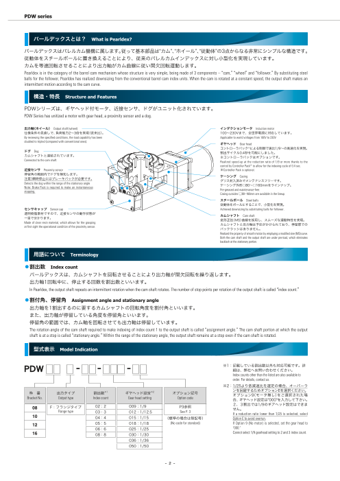
パールデックスはバレルカム機構に属します。従って基本部品は“カム”、“ホイール”、“従動体”の3点からなる非常にシンプルな構造です。
従動体をスチールボールに置き換えることにより、従来のバレルカムインデックスに対し小型化を実現しています。
カムを等速回転させることにより出力軸がカム曲線に従い間欠回転運動します。
Pearldex is in the category of the barrel cam mechanism whose structure is very simple, being made of 3 components – “cam,” “wheel” and “follower.” By substituting steel
balls for the follower, Pearldex has realized downsizing from the conventional barrel cam index units. When the cam is rotated at a constant speed, the output shaft makes an
intermittent motion according to the cam curve.
構造・特長 Structure and Features
PDWシリーズは、ギヤヘッド付モータ、近接センサ、ドグがユニット化されています。
PDW Series has unitized a motor with gear head, a proximity sensor and a dog.
出力軸(ホイール) Output shaft (wheel) インダクションモータ Induction motor
仕様条件の見直しで、負荷能力2~3倍を実現(従来比)。 100~230Vまで、全世界電源に対応しています。
By reviewing the specified conditions, the load capability has been Applicable to world voltages from 100V to 230V
doubled to tripled (compared with conventional ones). ギヤヘッド Gear head
コントローラパック※による制御で速比1/9~の高速化を実現。
ドグ Dog 割出サイクル0.4秒を可能にしました。
カムシャフトと連結されています。 ※コントローラパックはオプションです。
Connected to the cam shaft. Realized speed-up at the reduction ratio of 1/9 or more thanks to the
control by Controller Pack※ to allow for the indexing cycle of 0.4 sec.
近接センサ Proximity sensor ※Controller Pack is optional.
停留角の範囲内でドグを検知します。
注意)瞬時停止にはブレーキパックが必要です。 ケーシング Casing
グリス封入済みでメンテナンスフリーです。
Detects the dog within the range of the stationary angle ケーシング外形□80~□160mmをラインナップ。
Note: Brake Pack is required to make an instantaneous
stopping. Pre-greased and maintenance-free.
Casing outsides □80–160mm are available in the lineup.
スチールボール Steel balls
従動体をボールにすることで、小型化を実現。
センサキャップ Sensor cap Achieved downsizing by substituting balls for follower.
透明樹脂素材ですので、近接センサの動作状態が
一目で分かります。 カムシャフト Cam shaft
変形正弦(MS)曲線を採用し、スムーズな運動特性を実現。
Made of clear resin material, which allows for the grasping カムシャフトと出力軸は予圧がかけられており、停留部での
at first sight the operational condition of the proximity sensor. バックラッシはありません。
Realized the property of smooth motion by employing a modified sine (MS) curve.
Both the cam shaft and the output shaft are under pre-load, which eliminates
backlash at the stationary portion.
用語について Terminology
⃝割出数 Index count
パールデックスは、カムシャフトを回転させることにより出力軸が間欠回転を繰り返します。
出力軸1回転中に、停止する回数を割出数といいます。
In Pearldex, the output shaft repeats an intermittent rotation when the cam shaft rotates. The number of stop points per rotation of the output shaft is called “index count.”
⃝割付角、停留角 Assignment angle and stationary angle
出力軸を1割出するのに要するカムシャフトの回転角度を割付角といいます。
また、出力軸が停留している角度を停留角といいます。
停留角の範囲では、カム軸を回転させても出力軸は停留しています。
The rotation angle of the cam shaft required to make indexing of index count 1 to the output shaft is called “assignment angle.” The cam shaft portion at which the output
shaft is at a stop is called “stationary angle.” Within the range of the stationary angle, the output shaft remains at a stop even if the cam shaft is rotated.
型式表示 Model Indication
※1:記載している割出数以外も対応可能です。詳
PDW − − − 細は、弊社へお問い合わせください。
Index counts other than the listed are also available to
order. For details, contact us.
※2:1 /25より低減速比を選定の場合、オーバーラ
枠 番 出力タイプ 割出数※1 ギヤヘッド設定※2 オプション記号 ンを回避するためオプションEを選択ください。
オ プション9(モータ無し)をご選択された場
Bracket No. Output type Index count Gear head setting Option code 合、ギヤヘッド設定は"000"を入力して下さい。
2、3割出では1/9のギアヘッド設定はできま
08 F:フランジタイプ 02:2 009:1/9 P3参照
Flange type せん。
03:3 012:1/12.5 See P. 3
If a reduction ratio lower than 1/25 is selected, select
10 04:4 015:1/15 (標準の場合は無記号) Option E to avoid overrun.
12 05:5 018:1/18 (No code for standard) If Option 9 (No motor) is selected, set the gear head to
06:6 025:1/25 “000.”
16 08:8 030:1/30 Cannot select 1/9 gearhead setting to 2 and 3 index count.
036:1/36
050:1/50
- 2 -
Page3
オプション設定 Option Setting
−
ブレーキパックの選択 Selection of Brake Pack
無記号※1 ブレーキパック無し
No code No Brake Pack
E※2 コントローラパック(SB50W付属)
Controller Pack (with SB50W)
モータ仕様 Motor specifications F SB50W(無接点タイプ)
SB50W (non-contact type)
無記号 インダクションモータ(単相100V 50/60Hz) ※1:イ ンダクションモータの制御には瞬時停止用のブレーキパックが必要となります。
No code Induction motor (Single phase 100V, 50/60Hz) お客様にて準備されるか、オプション設定にてご選択ください。
For controlling the induction motor, Brake Pack for an instantaneous stopping is required.
1 インダクションモータ(単相200V 50/60Hz) Procure Brake Pack on your side or select Brake Pack in “Option Setting.”
Induction motor (Single phase 200V, 50/60Hz) ※2:ギ ヤヘッドを1/25より低減速比を選定の場合、Eを選択ください。
If a reduction ratio lower than 1/25 is selected, select “E.”
2 インダクションモータ(単相110/115V 60Hz)
Induction motor (Single phase 110/115V, 60Hz)
3 インダクションモータ(単相220/230V 50Hz)
Induction motor (Single phase 220/230V, 50Hz)
4 インダクションモータ(単相220/230V 60Hz)
Induction motor (Single phase 220/230V, 60Hz)
9 モータ無し
No motor
コントローラパックオプションについて Controller Pack (Option)
コントローラパック(オプション:E)は、単独制御の為、PLCスキャンタイムの影響を受けず瞬時停止を行います。1/25より低減
速比をご使用されるときは、コントローラパックを使用してブレーキ制御を行ってください。使用しない場合、オーバーラン発生
の恐れがございます。
Controller Pack (Option E), which is designed for independent control, performs an instantaneous stopping without being affected by the PLC scan time. If a reduction ratio lower than
1/25 is used, use Controller Pack to perform brake control. If Controller Pack is not used, overrun could occur.
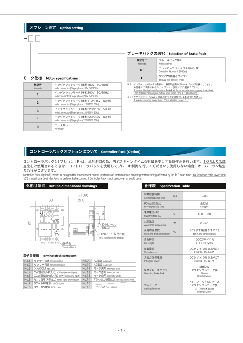
外形寸法図 Outline dimensional drawings 仕様表 Specification Table
(109) 制御応答時間 ms 2±0.5
Control response time
100 (91)
PDW対応型式 全型式
1 2 3 4 5 6 7 8 PDW supportive type All types
電源電圧-AC V 100~230
Power voltage-AC
対応温度
DINレール ℃ 0~40
Applicable temperature
DIN rail
SB50W 使用周囲湿度 % 85%以下(結露なきこと)
DINレール取付け足 Operating ambient humidity ≦85% (no condensation)
DIN rail mounting bracket 寿命時間 1000万サイクル
910111213141516 端子台 Life length 10,000,000 cycles
Terminal block 制御電源 DC24V±10% 0.2A以上
Control power 24VDC±10%, ≧0.2A
端子台接続 Terminal block connection 入出力信号電源 DC24V±10% 0.2A以下
No.1 センサー青用For sensor blue No.9 AC電源AC power I/O signal power 24VDC±10%, ≦0.2A
No.2 センサー茶用For sensor brown No.10 AC電源AC power
No.3 入力COMInput COM No.11 モータ黒用 SB50W
For motor black 使用ブレーキパック オリエンタルモータ製
No.4 CW運転(外部入力)CW run (external input) No.12 モータ赤用For motor red Operating Brake Pack SB50W
No.5 CCW運転(外部入力)CCW run (external input) No.13 モータ白用For motor white Oriental Motor
No.6 センサ信号(外部出力)Sensor signal (external output) No.14 アラーム出力(外部出力)Alarm output (external output)
No.7 DC+24V電源 KⅡ・ワールドKシリーズ
+24VDC power No.15 対応モータ
No.8 DC 0V電源 オリエンタルモータ製
0VDC power No.16 出力COMOutput COM Applicable motor KII – World K Series
Oriental Motor
- 3 -
120
45
Page4
PDW series
外形寸法図及び仕様表 Outside Dimensional Drawing and Specifications
⃝PDW08F型(フランジタイプ)
※停留位置と出力軸タップ位置の関係は図の通りとなります。
Model PDW08F (Flange type) The relationship between the stationary position and the top position of output shaft is as shown in the figure
点検用ゴムキャップ 停留位置 Stationary position
Access Rubber Cap 31 ☆4
(74) (30)
4×M5 深さ10
2×M6 深さ14(裏面同加工) 4×M5 Depth 10
2×M6 Depth 14 (Backside: Same Processing)
5
(保護接地端子)
2×M6 深さ11(裏面同加工) 25 (Protective earth terminal)
3.5
2×M6 Depth 11 (Backside: Same Processing) 68 ギヤヘッド速比
C 13 80 20 (4.2) A B ☆C 11 11
☆ Gear head reduction ratio
A (117.2) 1/9~25 109 (226.2) 42 (5) 10 62
B 1/30~50 113 (230.2) 46 (77)
仕様表(ギヤヘッド速比1/25) Specification table (Gear head reduction ratio: 1/25)
50Hz 60Hz
ロッキング 許容荷重 質量
割出サイクル 許容 owable load Mass
割出数 トルク 割出トルク イクル 許容
時間 慣性モーメント 割出トルク 割出サ All
モーメント N kg
Index count Locking torque 時間 慣性
Indexing torque Indexing torque
Indexing cycle time Allowable inertia moment Indexing cycle time Allowable inertia moment
ラジアル アキシャル F型
N・m N・m 秒 sec ×10-⁴ kg・m² N・m 秒 sec ×10-⁴ kg・m² Radial Axial Model F
2 0.92 573 0.75 321
3 1.38 1288 1.13 722
4 1.65 1669 1.35 936
6.9 1.3 1.0 245 147 3.1
5 2.06 1750 1.69 1462
6 2.48 1750 2.03 1750
8 3.30 1750 2.70 1750
●モータ オリエンタルモータ製KⅡシリーズ 2IK6GV-JA+2GV25B
Motor: Oriental Motor KII Series 2IK6GV-JA+2GV25B
※モータ無し(オプション:9)を選択された場合、モータは必ずKⅡシリーズをご使用ください。それ以外は取付できません。
また、モータに保護接地端子が☆部寸法位置に付いています。取付部との干渉等にご注意ください。
オプション:9以外は、保護接地端子は取外して出荷致します。
※ If “No motor” (Option 9) is selected, be sure to use a motor of KII Series. Any other motor is not mountable. The motor is equipped with a protective earth terminal in the dimensional position marked with ☆.
Watch our for interference or the like trouble of the terminal with the mounting portion. For any option other than Option 9, the protective earth terminal is removed before shipping.
●割出確認センサ オムロン製近接センサ E2S-W21(直流2線式)
Index confirmation sensor: OMRON Proximity Sensor E2S-W21 (DC 2-wire type)
●モータギヤヘッド取付ボルトサイズ M4×50(ギヤヘッド速比30以上はM4×55)
Motor gear head mounting bolt size: M4×50 (M4×55 for gear head speed ratios 30 and more)
●標準ギヤヘッド(1/25)以外の割出サイクル時間、割出トルク及び許容慣性モーメントは、右記をご参照ください。2、3割出は、1/12.5~の対応となります。
For the indexing cycle time with a gear head other than the standard gear head (1/25) and the indexing torque and the allowable inertia moment, refer to the right description. Index counts 2 and 3 are supported by 1/12.5 and more.
●仕様表以外の割出数、ギヤヘッド速比も対応可能です。詳細は、弊社までお問い合わせください。
Index counts and gear head reduction ratios not listed in the specification table can also be available to order. For details, contact us.
●割出サイクル時間は連続回転駆動の場合の数値です。断続駆動の場合、モータ立ち上がり時間や制御でのプログラムタイムラグを考慮する必要があります。
The value of the indexing cycle time for the case of continuous rotary drive. In the case of intermittent drive, program time lag in motor rise time or control should be taken into account.
- 4 -
□60
20
40 43 (5)
68
88
φ80h8
φ35h7(回転部)
(Rotating part)
φ14H7
☆5.5
φ60H8
Page5
外形寸法図及び仕様表 Outside Dimensional Drawing and Specifications
速比別能力表 Capability table specific to speed ratio
⃝割出サイクル時間(秒) Indexing cycle time (sec)
ギヤヘッド速比
使用周波数 Gear head reduction ratio
Operating frequency
1/9 1/12.5 1/15 1/18 1/25 1/30 1/36 1/50
50Hz 0.5 0.6 0.8 0.9 1.3 1.5 1.8 2.5
60Hz 0.4 0.5 0.6 0.7 1.0 1.2 1.5 2.1
⃝割出トルク・許容慣性モーメント Indexing torque and allowable inertia moment
50Hz
3.5 3.43 3.43 3.43 1800 1/50
1750 1750 1750 1750 1750 1750
3.30 3.38 3.30
1/50 1/36 1669
1/36 1/30 1600 1/18
3.0 1/30
2.93 1500
2.75 2.81 1486 1/15
1/25 1400 1/25 1434
2.5 2.44 2.48 2.43 1/18 1288
1200
2.25
2.0 2.06 2.04 1/15
1.95 1000
1.83 1.88 974 996
1.82
1.63 1.65 1.68 1/12.5 850 1/12.5
800 836
1.5 1.52 1.53
1.38
1.25 1.22 1.28 1.26 1.23 1/9 600 637
1.08 573
1.0 1.01 1.02 1.05 581
0.92 492 478
0.85 0.84 0.92
0.68 0.70 0.77 400 372
0.57 0.62 332 323
0.50.47 287 1/9
200219 212
127 164 181
73 126
81
0.0 0
2 3 4 5 6 8 2 3 4 5 6 8
割出数 Index count 割出数 Index count
60Hz
3.5 3.43 3.43 1800 1/50
1/50 1750 1750 1750 1750 1750 1750
3.19
1/36 1600
3.0 3.00 1/30 1/36
1497
1462
2.70 2.70 1/25 1400 1401 1/18
2.5 2.55 1/30
1200
2.25 2.25 1155
2.13 1/25
2.0 2.03
1.88 1.95 1/18 1000
1.80 887 936
1.69
1.62 1/15
1.5 800 788 808 1/15
1.50 1.50
1.42 1.46
1.35 1.35 1/12.5 722
1.25 1.22 1.22
1.13 600
1.01.00 547
0.98 1.01 1.01 0.96 1/9 513
0.83 455 468 1/12.5
0.81 0.81 0.84
0.75 400
0.68 0.68 0.72
0.54 321 350
0.5 0.56 0.60 316
0.45 0.48 270 263
0.38 200120 202
156 183 172 1/9
69
40 90 117
4 67 97
3
0.0 0
2 3 4 5 6 8 2 3 4 5 6 8
割出数 Index count 割出数 Index count
- 5 -
割出トルク Indexing torque (N・m) 割出トルク Indexing torque (N・m)
許容慣性モーメント Allowable inertia moment (×10-4 kg・m2) 許容慣性モーメント Allowable inertia moment (×10-4 kg・m2)
Page6
PDW series
外形寸法図及び仕様表 Outside Dimensional Drawing and Specifications
⃝PDW10F型(フランジタイプ)
※停留位置と出力軸タップ位置の関係は図の通りとなります。
Model PDW10F (Flange type) The relationship between the stationary position and the top position of output shaft is as shown in the figure
停留位置 Stationary position
4×M6 深さ15 点検用ゴムキャップ 36 ☆4
4×M6 Depth 15 (74) Access Rubber Cap (30)
4×M8 深さ16(裏面同加工)
4×M8 Depth 16 (Backside: Same Processing)
6
35
(保護設置端子)
85 4 (Protective earth terminal)
☆C 13 100 20 (4.2) ギヤヘッド速比 A B ☆C 9 16 16
A (137.2) Gear head reduction ratio (6)
B 18 72
1/9~25 118 (255.2) 59.5 (96)
1/30~50 123 (260.2) 64.5
仕様表(ギヤヘッド速比1/25) Specification table (Gear head reduction ratio: 1/25)
50Hz 60Hz
ロッキング 許容荷重 質量
ク 割出トルク 割出サイクル 許容 サイクル 許容 Allowable load Mass
割出数 トル
時間 慣性モーメント 割出トルク 割出
N kg
Index count Locking torque 時間 慣性モーメント
Indexing torque Indexing torque
Indexing cycle time Allowable inertia moment Indexing cycle time Allowable inertia moment
ラジアル アキシャル F型
N・m N・m 秒 sec ×10-⁴ kg・m² N・m 秒 sec ×10-⁴ kg・m² Radial Axial Model F
2 2.3 1222 1.9 766
3 3.4 2750 2.9 1724
4 4.1 3960 3.5 2234
13.2 1.3 1.0 343 196 5.0
5 5.1 5000 4.3 3491
6 6.1 5000 5.2 5000
8 6.6 5000 6.6 5000
●モータ オリエンタルモータ製KⅡシリーズ 3IK15GV-JA+3GV25B
Motor: Oriental Motor KII Series 3IK15GV-JA+3GV25B
※モータ無し(オプション:9)を選択された場合、モータは必ずKⅡシリーズをご使用ください。それ以外は取付できません。
また、モータに保護接地端子が☆部寸法位置に付いています。取付部との干渉等にご注意ください。
オプション:9以外は、保護接地端子は取外して出荷致します。
※ If “No motor” (Option 9) is selected, be sure to use a motor of KII Series. Any other motor is not mountable. The motor is equipped with a protective earth terminal in the dimensional position marked with ☆.
Watch our for interference or the like trouble of the terminal with the mounting portion. For any option other than Option 9, the protective earth terminal is removed before shipping.
●割出確認センサ オムロン製近接センサ E2S-W21(直流2線式)
Index confirmation sensor: OMRON Proximity Sensor E2S-W21 (DC 2-wire type)
●モータギヤヘッド取付ボルトサイズ M6×55(ギヤヘッド速比30以上はM6×60)
Motor gear head mounting bolt size: M6×55 (M6×60 for gear head speed ratios 30 and more)
●標準ギヤヘッド(1/25)以外の割出サイクル時間、割出トルク及び許容慣性モーメントは、右記をご参照ください。2、3割出は、1/12.5~の対応となります。
For the indexing cycle time with a gear head other than the standard gear head (1/25) and the indexing torque and the allowable inertia moment, refer to the right description. Index counts 2 and 3 are supported
by 1/12.5 and more.
●仕様表以外の割出数、ギヤヘッド速比も対応可能です。詳細は、弊社までお問い合わせください。
Index counts and gear head reduction ratios not listed in the specification table can also be available to order. For details, contact us.
●割出サイクル時間は連続回転駆動の場合の数値です。断続駆動の場合、モータ立ち上がり時間や制御でのプログラムタイムラグを考慮する必要があります。
The value of the indexing cycle time for the case of continuous rotary drive. In the case of intermittent drive, program time lag in motor rise time or control should be taken into account.
- 6 -
□70
25
50 50 (5)
85
105
φ100h8
φ77
φ50h7(回転部)
(Rotating part)
φ20H7
☆3.5
φ80H8
Page7
外形寸法図及び仕様表 Outside Dimensional Drawing and Specifications
速比別能力表 Capability table specific to speed ratio
⃝割出サイクル時間(秒) Indexing cycle time (sec)
ギヤヘッド速比
使用周波数 Gear head reduction ratio
Operating frequency
1/9 1/12.5 1/15 1/18 1/25 1/30 1/36 1/50
50Hz 0.5 0.6 0.8 0.9 1.3 1.5 1.8 2.5
60Hz 0.4 0.5 0.6 0.7 1.0 1.2 1.4 2.0
⃝割出トルク・許容慣性モーメント Indexing torque and allowable inertia moment
50Hz
1/50
7.0 5000 5000 5000 5000 5000 5000
6.6 6.6 6.6 6.6 1/36
6.5
1/50 1/30 1/30
6.0 6.1
5.8 4167 1/25
1/18
1/36 5.6 5.7 4000 3938 3960 1/18
1/25
5.0 5.1
3497 1/15
1/15
4.6 4.7 4.8 3363
4.3 4.3
4.0 4.1 4.2 1/12.5 3000
3.9 2750
3.6 3.6 2500
3.4
3.1 3.2 2336
3.0 2.9 3.0 2.9 1/9 2125 1/12.5
2000 1967
2.6 2.6 1750
2.3 2.4 2.4
2.0 2.0 2.1 2.2 1495
1 1.8 1.8 1222 1366
.6 1153 1195
1.3 1.5 1000
1.2 874
1.0 830 763 1/9
675
513 531
300 410 429
182 298
191
0.0 0
2 3 4 5 6 8 2 3 4 5 6 8
割出数 Index count 割出数 Index count
60Hz
1/50
7.0 5000 5000 5000 5000 5000 5000
6.5 6.6 6.6 6.6 4818
1/50 1/36
6.0 1/36 1/30
5.8 5.9 4167
4000
5.4 1/30
5.2 1/25
5.0 4.9 3637
4.7 4.8 1/18 3491
1/25 3223 1/18
4.3 4.2 1/15
4.0 3000
3.9 3.9 2806
3.6 3.6
3.5
3.3 1/12.5
3.0 3.2 3.3
2.9 3.0 2141 2234
2000
2.6 2.6 1958 1/15
2.4 2.5 1813
1724
2.2 2.4 1/9
2.0 2.0 2.1 2.1
1.9 1.8 1.7 1.8 1247 1259
1.3 1.4 1.5 1000 1101 1068 1/12.5
1.0 1.2 1.2
0.9 766 806 765
622
276
378 490 610
168 417 408 1/9
92 206 267
2 159 229
10
0.0 0
2 3 4 5 6 8 2 3 4 5 6 8
割出数 Index count 割出数 Index count
- 7 -
割出トルク Indexing torque (N・m) 割出トルク Indexing torque (N・m)
許容慣性モーメント Allowable inertia moment (×10-4 kg・m2) 許容慣性モーメント Allowable inertia moment (×10-4 kg・m2)
Page8
PDW series
外形寸法図及び仕様表 Outside Dimensional Drawing and Specifications
⃝PDW12F型(フランジタイプ)
※停留位置と出力軸タップ位置の関係は図の通りとなります。
Model PDW12F (Flange type) The relationship between the stationary position and the top position of output shaft is as shown in the figure
停留位置 Stationary position 41 ☆ 4
4×M6 深さ15 (74) (30)
4×M6 Depth 15 点検用ゴムキャップ
Access Rubber Cap
2×M10 深さ18(裏面同加工)
2×M10 Depth 18 (Backside: Same Processing) (保護接地端子)
(Protective earth terminal)
7
50
2×M10 深さ16(裏面同加工)
2×M10 Depth 16 (Backside: Same Processing)
105 6
☆C 15 125 23 (4.2) ギヤヘッド速比 A B ☆C 10 16 16
Gear head reduction ratio
A (167.2) 1/9~25 126 (293.2) 62.5 (7) 19 82
B 1/30~50 131 (298.2) 67.5 (108)
仕様表(ギヤヘッド速比1/25) Specification table (Gear head reduction ratio: 1/25)
50Hz 60Hz
ロッキング 許容荷重 質量
ク 割出サイクル 許容 イクル 許容 Allowable load Mass
割出数 トルク 割出トル 時間 慣性モーメント 割出トルク 割出サ
N kg
Index count Locking torque 時間 慣性モーメント
Indexing torque Indexing torque
Indexing cycle time Allowable inertia moment Indexing cycle time Allowable inertia moment
ラジアル アキシャル F型
N・m N・m 秒 sec ×10-⁴ kg・m² N・m 秒 sec ×10-⁴ kg・m² Radial Axial Model F
2 3.6 1528 3.0 1123
3 5.4 3438 4.5 2527
4 6.5 4950 5.4 3275
24.5 1.2 1.0 490 294 8.6
5 8.1 7500 6.8 5117
6 9.7 7500 8.1 7368
8 12.3 7500 10.8 7500
●モータ オリエンタルモータ製KⅡシリーズ 4IK25GV-JA+4GV25B
Motor: Oriental Motor KII Series 4IK25GV-JA+4GV25B
※モータ無し(オプション:9)を選択された場合、モータは必ずKⅡシリーズをご使用ください。それ以外は取付できません。
また、モータに保護接地端子が☆部寸法位置に付いています。取付部との干渉等にご注意ください。
オプション:9以外は、保護接地端子は取外して出荷致します。
※ If “No motor” (Option 9) is selected, be sure to use a motor of KII Series. Any other motor is not mountable. The motor is equipped with a protective earth terminal in the dimensional position marked with ☆.
Watch our for interference or the like trouble of the terminal with the mounting portion. For any option other than Option 9, the protective earth terminal is removed before shipping.
●割出確認センサ オムロン製近接センサ E2S-W21(直流2線式)
Index confirmation sensor: OMRON Proximity Sensor E2S-W21 (DC 2-wire type)
●モータギヤヘッド取付ボルトサイズ M6×60(ギヤヘッド速比30以上はM6×65)
Motor gear head mounting bolt size: M6×60 (M6×65 for gear head speed ratios 30 and more)
●標準ギヤヘッド(1/25)以外の割出サイクル時間、割出トルク及び許容慣性モーメントは、右記をご参照ください。2、3割出は、1/12.5~の対応となります。
For the indexing cycle time with a gear head other than the standard gear head (1/25), the indexing torque and the allowable inertia moment, refer to the right description. Index counts 2 and 3are supported by
1/12.5 and more.
●仕様表以外の割出数、ギヤヘッド速比も対応可能です。詳細は、弊社までお問い合わせください。
Index counts and gear head reduction ratios not listed in the specification table can also be available to order. For details, contact us.
●割出サイクル時間は連続回転駆動の場合の数値です。断続駆動の場合、モータ立ち上がり時間や制御でのプログラムタイムラグを考慮する必要があります。
The value of the indexing cycle time for the case of continuous rotary drive. In the case of intermittent drive, program time lag in motor rise time or control should be taken into account.
- 8 -
□80
32.5
62.5 62.5 (5)
105
130
φ124h8
φ96
φ65h7(回転部)
(Rotating part)
φ30H7
☆ 3
φ100H8
Page9
外形寸法図及び仕様表 Outside Dimensional Drawing and Specifications
速比別能力表 Capability table specific to speed ratio
⃝割出サイクル時間(秒) Indexing cycle time (sec)
ギヤヘッド速比
使用周波数 Gear head reduction ratio
Operating frequency
1/9 1/12.5 1/15 1/18 1/25 1/30 1/36 1/50
50Hz 0.4 0.6 0.7 0.9 1.2 1.4 1.7 2.4
60Hz 0.4 0.5 0.6 0.7 1.0 1.2 1.4 2.0
⃝割出トルク・許容慣性モーメント Indexing torque and allowable inertia moment
50Hz
14.0 8000
7500 7500 7500 7500 7500
1/50
12.0 12.3 12.3 12.3 12.3 7000 7200
6875
1/50 1/36
1/36 11.1 11.0
1/30 60006111 1/25
10.0 10.3 1/18
9.7 1/25 1/30
9.2 9.3 1/18 5237 1/15
8.9 5000 5000 4950 5058
8.0 8.1
7.8 1/15
7.4 7.4
6.8 7.0 4000
6.5
6.0 6.1 6.3 1/12.5
3438 3512
5.8 5.9
5.4
4.9 4.7 4.9 30003056 2946 2937 1/12.5
4.7
4.1 4.5 1/9
4.0
3.6 3.9 3.9 3.9 2222 2248
2046
3.3 3.2 3.4 2000
2.6 2.6 2.8 1734
1528 1652
2.0 2.2
2.3 1309
1.8 1000 1010 1147 1088 1/9
771
449 567 734 612
252 425
272
0.0 0
2 3 4 5 6 8 2 3 4 5 6 8
割出数 Index count 割出数 Index count
60Hz
14.0 8000
7500 7500 7500 7500 7500
1/50 7368
12.0 12.3 12.3 12.3 7000 6875
1/50
11.3
10.8 6111 1/36
10.4 6000
10.0 1/30 1/30
5371 1/25
1/36 9.4 9.2
8.6 1/25 5000 5117
4904 1/18
8.0 8.1
7.5 7.7 7.8 1/18
4000 4144
6.8 6.6 1/15
6.3
6.0 6.2 5.9
5.8 3056 3275
5.4 5.4 1/12.5
5.1 4.9 5.0 3000
2759 2882 1/15
4.2 4.5 2527
4.0 3.9 4.1 4.1
3.9 1/9
3.4
3.0 3.3 3.3 3.4 2000 1916
2.8 2.7 2.9 1842 1621 1637 1/12.5
2.2 2.4
2.0 2.3
1.8 2.0 1123 1226
1000 1126
1.5 946 921
420 556 720 640
247 613 1/9
316 409
140 153 239 345
0.0 0
2 3 4 5 6 8 2 3 4 5 6 8
割出数 Index count 割出数 Index count
- 9 -
割出トルク Indexing torque (N・m) 割出トルク Indexing torque (N・m)
許容慣性モーメント Allowable inertia moment (×10-4 kg・m2) 許容慣性モーメント Allowable inertia moment (×10-4 kg・m2)
Page10
PDW series
外形寸法図及び仕様表 Outside Dimensional Drawing and Specifications
⃝PDW16F型(フランジタイプ)
※停留位置と出力軸タップ位置の関係は図の通りとなります。
Model PDW16F (Flange type) The relationship between the stationary position and the top position of output shaft is as shown in the figure
停留位置 Stationary position 46 ☆ 4
4×M8 深さ16 (74)
4×M8 Depth 16 点検用ゴムキャップ (30) ☆ 1.4
Access Rubber Cap
2×M12 深さ20(裏面同加工)
2×M12 Depth 20 (Backside: Same Processing) (ファンカバー取付ボルト)
(Fan Cover Mounting Bolt)
8
70
2×M12 深さ16(裏面同加工) (保護接地端子)
2×M12 Depth 16 (Backside: Same Processing) (Protective earth terminal)
135 6
☆C 10 160 12 (4.2) ギヤヘッド速比 A B ☆C
Gear head reduction ratio 10 16 16
A (186.2) 1/9~18 165 (351.2) 53 (8) 24 92
B 1/25~50 178 (364.2) 66 (124)
仕様表(ギヤヘッド速比1/25) Specification table (Gear head reduction ratio: 1/25)
50Hz 60Hz
ロッキング 許容荷重 質量
許容 Allowable load Mass
割出数 トルク 割出トルク 割出サイクル 許容
時間 慣性モーメント 割出トルク 割出サイクル
慣性モーメント N kg
Index count Locking torque 時間
Indexing torque Indexing torque
Indexing cycle time Allowable inertia moment Indexing cycle time Allowable inertia moment
ラジアル アキシャル F型
N・m N・m 秒 sec ×10-⁴ kg・m² N・m 秒 sec ×10-⁴ kg・m² Radial Axial Model F
2 8.1 3056 6.8 2558
3 12.1 6875 10.3 5756
4 14.6 9900 12.3 7459
51.5 1.2 1.0 735 490 14.8
5 18.2 12500 15.4 11655
6 21.8 12500 18.5 12500
8 25.7 12500 24.6 12500
●モータ オリエンタルモータ製KⅡシリーズ 5IK60GVH-JA+5GVH25B
Motor: Oriental Motor KII Series 5IK60GVH-JA+5GVH25B
※モータ無し(オプション:9)を選択された場合、モータは必ずKⅡシリーズをご使用ください。それ以外は取付できません。
また、モータの保護接地端子及びファンカバー取付ボルトが☆部寸法の通り付いています。取付部との干渉等にご注意ください。
オプション:9以外は、保護接地端子は取外し、ファンカバー取付ボルトは皿ねじに交換して出荷致します。
※ If “No motor” (Option 9) is selected, be sure to use a motor of KII Series. Any other motor is not mountable. The motor is equipped with a protective earth terminal in the dimensional position marked with ☆.
Watch our for interference or the like trouble of the terminal with the mounting portion. For any option other than Option 9, the protective earth terminal is removed before shipping.
●割出確認センサ オムロン製近接センサ E2S-W21(直流2線式)
Index confirmation sensor: OMRON Proximity Sensor E2S-W21 (DC 2-wire type)
●モータギヤヘッド取付ボルトサイズ M8×75(ギヤヘッド速比9~18はM8×60)
Motor gear head mounting bolt size: M8×75 (M8×60 for gear head speed ratios 9–18)
●標準ギヤヘッド(1/25)以外の割出サイクル時間、割出トルク及び許容慣性モーメントは、右記をご参照ください。2、3割出は、1/12.5~の対応となります。
For the indexing cycle time with a gear head other than the standard gear head (1/25) and the indexing torque and the allowable inertia moment, refer to the right description. Index counts 2 and 3 are supported
by 1/12.5 and more.
●仕様表以外の割出数、ギヤヘッド速比も対応可能です。詳細は、弊社までお問い合わせください。
Index counts and gear head reduction ratios not listed in the specification table can also be available to order. For details, contact us.
●割出サイクル時間は連続回転駆動の場合の数値です。断続駆動の場合、モータ立ち上がり時間や制御でのプログラムタイムラグを考慮する必要があります。
The value of the indexing cycle time for the case of continuous rotary drive. In the case of intermittent drive, program time lag in motor rise time or control should be taken into account.
- 10 -
□90
45
80 80 (5)
135
165
φ160h8
φ130
φ85h7(回転部)
(Rotating part)
φ40H7
☆ 10.5
φ120H8
Page11
外形寸法図及び仕様表 Outside Dimensional Drawing and Specifications
速比別能力表 Capability table specific to speed ratio
⃝割出サイクル時間(秒) Indexing cycle time (sec)
ギヤヘッド速比
使用周波数 Gear head reduction ratio
Operating frequency
1/9 1/12.5 1/15 1/18 1/25 1/30 1/36 1/50
50Hz 0.4 0.6 0.7 0.8 1.2 1.4 1.7 2.3
60Hz 0.3 0.5 0.6 0.7 1.0 1.2 1.4 1.9
⃝割出トルク・許容慣性モーメント Indexing torque and allowable inertia moment
50Hz
30.0 14000
1/50
12500 12500 12500 12500 12500 12500
1/50 12000
25.0 25.7 25.7 25.7 25.7
24.3 1/36 11359 1/15
1/36 1/30 1/25 1/30 11011
21.8 21.8 21.9 1/18
20.9 10000 10000 9900
20.0
1/25
18.2 18.3 1/15
17.4 17.4 8000 1/18
16.2 16.4 7647
15.0 15.3 1/12.5
14.5 14.6 6389 6875 6595 1/12.5
13.7 13.7 6390
6000
11.6 12.1
11.0 11.4 11.5 10.8 1/9
10.0 4894
9.7
9.1 9.2 9.6 4444 4437
8.1 8.1 4000
7.6 7.7 3776 3710
6.1 6.4 6.8 3056 2840
5.0 5.1 5.4 2576
2191 2413 1/9
2000
4.3 1678 1649
974 1272 1358
565 943
603
0
2 3 4 5 6 8 2 3 4 5 6 8
割出数 Index count 割出数 Index count
60Hz
30.0 14000
1/50
12500 12500 12500 12500 12500 12500
25.0 25.7 25.7 25.7 12000
1/50 24.5 24.6 1/36 11655 11695 1/18
1/30
22.1 22.1
1/36 10000 9905
20.0 20.4 1/30 1/25 1/25
18.4 18.5 18.6 1/18
17.7 8000
7459
15.0 15.4 15.3 1/15
14.8 14.7 14.0 6389 6579 6681 1/15
13.6 12.9 1/12.5
12.3 12.3 6000 5756
11.6 11.5
10.0 9.8 10.3 4402 4568
9.3 9.6 9.7 9.3 1/9
8.2 4000 3758 3912 1/12.5
7.8 7.7 8.1
6.8 6.4 6.5 7.0 2924
5.0 5.2 5.4 5.8 2558 2610
4.3 4.7 2000 2256 2200
3.6 1670
1003 1289 1528 1462 1/9
573 755 978
365 571 822
335
0.0 0
2 3 4 5 6 8 2 3 4 5 6 8
割出数 Index count 割出数 Index count
- 11 -
割出トルク Indexing torque (N・m) 割出トルク Indexing torque (N・m)
許容慣性モーメント Allowable inertia moment (×10-4 kg・m2) 許容慣性モーメント Allowable inertia moment (×10-4 kg・m2)
Page12
PDW series
パールデックスの精度 Precision of Pearldex
index count 4
Indexing accuracy
Bidirectional positioning accuracy
1 rotation of the output shaft
⃝割出精度 Indexing accuracy
目標とする割出角度(理論角度)と実際動作角度との最大差を±で表す
The maximum difference indicated in “±” between the target indexing angle (theoretical angle) and the actual operating angle
⃝二方向位置決め精度 Bidirectional positioning accuracy
正逆回転で割出を行う場合の停止位置に対する正逆戻り誤差の最大値を表す
The maximum value of the CW/CCW hysteresis error with respect to the stopping position when indexing is made both in the CW/CCW rotation
⃝繰返し位置決め精度 Repetitive positioning accuracy
1方向回転にて、基準回数の割出を行った場合の停止位置のバラツキ(位置再現性)を表す
Dispersion (positional reproducibility) in the stopping position when indexing is made for the reference index count in one-way rotation
⃝各型式割出精度 Indexing accuracy of each model
型 式 割出精度 二方向位置決め 繰返し位置決め
Indexing accuracy Bidirectional positioning Repetitive positioning
Model arcsec arcsec arcsec
PDW 08 ± 90 90 30
PDW 10 ± 90 90 30
PDW 12 ± 90 90 30
PDW 16 ± 90 90 30
- 12 -
Angular error
Page13
使用・取扱いの方法 How to Use and Handle
⃝入出力回転方向 I/O rotational direction
モータをCW運転入力した時の出力軸回転方向は以下表の様になります。
The rotational direction of the output shaft when the CW rotation input is made to the motor is as shown in the following table:
ギヤヘッド速比
型 式 Gear head reduction ratio
Model
1/9 1/12.5 1/15 1/18 1/25 1/30 1/36 1/50
PDW08 CCW CW
PDW10 CCW CW
PDW12 CCW CW
PDW16 CCW CW
出力軸回転方向
Rotational direction of output shaft
CCW CW
⃝モータ制御方法について How to control the motor
PDWは、モータ一体の単独割出機としています。そのため断続運転が可能であり、割出をしたいときにモータを回して割出します。
このモータの起動・停止は必ずカムシャフトの停留角内で行う必要があるために、PDWタイプでは近接センサとモー
タ瞬時停止用のブレーキパック(オリエンタルモータ製 SB50W)を使用してカムシャフトを停留角内で停止させます。
また、低減速ギヤ比をご使用の場合、ブレーキパックを使用しても制御機器の遅れ等によりオーバーランが発生する可能
性がございますのでギヤヘッド速比が1/25より低減速の場合は、コントローラパック(オプションE)をご使用ください。
PDW Series is a motor-integrated independent index unit. For this motor-integrated structure, this series allows for intermittent operation. When indexing is to be made, the motor is rotated.
The motor should be started/stopped unexceptionally within the stationary angle. For PDW Series, therefore, the cam shaft is stopped within the stationary angle range by
using a proximity sensor and Brake Pack for an instantaneously stopping of the motor (Oriental Motor SB50W). When a low reduction ratio is used, even if Brake Pack is
used, overrun could occur due to delay or the like in the controller. For this reason, if a reduction ratio lower than 1/25 is used, use Controller Pack (Option E).
⃝PDWでの起動・停止の頻度について Starting/stopping frequency of PDW Series
PDWは、単相インダクションモータを使用しています。
制御は停留角内で寸動停止させるために近接センサとブレーキパックを使用しています。機械的ブレーキと違って摩
擦部分がなく長寿命です。但し、電気的にブレーキをかけるため、モータの温度上昇が発生します。短サイクル運転
でご使用の場合は特に注意が必要です。
ブレーキパックを使用しての運転サイクルの目安は、モータ本体温度が90℃以下の範囲となります。但し、ここまで
温度を上げて使用しますとモータの寿命が短くなりますので、注意して下さい。
また、停止時間PDW08~12は1秒以下、PDW16は2秒以下の短サイクルでご使用される場合には、弊社までお問い合わせ下さい。
PDW Series uses a single-phase induction motor. For control, this series uses a proximity sensor and Brake Pack to make inching and stopping within the stationary angle
range. Unlike the mechanical brake, this braking system has no friction portion, and, therefore, has a long service life. However, because brake is applied electrically, the
motor temperature goes up. For this reason, particular care should be directed to use for short-cycle operation.
When Brake Pack is used, operation should be permitted within the range of motor temperature of 90ºC or less as a rough indication. However, it should be noted that if the
motor temperature is raised this much high during operation, the service life of the motor would be shortened.
When PDW Series is used for short-cycle operation of outage time 1 sec or less for PDW08–12 or 2 sec or less for PDW16, contact us for consultation.
⃝設計上の注意 Notes for designing
□本体のオイルシールは内部グリース用の簡易シールです。使用条件や取付姿勢によっては油分が外部ににじみ出る
事があります。特に点検用ゴムキャップが下側となる姿勢でのご使用はご遠慮下さい。
The oil seal of the main unit is a simple seal for internal grease. Depending on the use conditions or mounted posture, grease may ooze out. Particularly, do not use PDW
Series with an access rubber cap on the downside.
□防滴・防塵使用とはなっておりません。対策が必要の場合はご相談下さい。
PDW Series is not drip-proof or dust-proof. If measures are required to counter drips or dust, contact us for consultation.
- 13 -
Page14
PDW series
使用・取扱いの方法 How to Use and Handle
⃝PDWシリーズ、ブレーキパックの制御方法について How to control Brake Pack for PDW Series
近接センサとブレーキパックでの参考制御回路を記載しますので参考にしてください。
※ブレーキパックの詳細につきましては、取説をご確認ください。
The control circuits for PDW Series with a proximity sensor and Brake Pack are shown below just for reference.
※For details of Brake Pack, refer to its instruction manual.
[シーケンス図] Sequence Diagram
・SB50Wを使用する場合
When SB50W is used
DC0V・24V
PLC DC24V
OUTPUT
メイン電源MS1オン Main Power MS1 ON Y00 MS1
CW運転出力 AC電源
CW Run Output Y01 8 6
AC Power
CCW運転出力 CCW Run Output Y02 5 オリエンタルモーター MS1 100~230V
Y03 DC24V・0V フ レ゙ーキハッ゚ク 2
DC24V・0V
出力COM SB50W
Output COM Y--
Oriental Motor
INPUT DC0V 黒 Black
Brake Pack
PB0 SB50W
X00 メイン電源MS1オン Main Power MS1 ON 1 赤 Red M
PB1 白 White
X01 メイン電源MS1オフ Main Power MS1 OFF 7 11
ワンショット信号 One-Shot Signal
DC0V・24V X02 CW運転入力 CW Run Input
ワンショット信号 One-Shot Signal コンデンサ
近接センサ Proximity Sensor X03 CCW運転入力 CCW Run Input Capacitor
E2S-W21 1M X04 センサー入力 Sensor Input
X-- 入力COM Input COM
近接センサ Proximity Sensor
E2S-W21 1M
茶 ※
Brown SB50WはSINK(NPN)/SOURCE(PNP)の切り替えが可能です。
負荷 Load +24V SB50Wへ信号入力の際はSINK/SOURCEをご確認の上ご使用ください。
近接センサ主回路
Main circvit of proximity sensor SB50W can be switched over to SINK (NPN) / SOURCE (PNP).
青 Blue When inputting a signal to SB50W, confirm SINK/SOURCE beforehand.
0V
※印部の負荷は、+24側、0側どちらにも接続可能です。
The load on the ※-marked portion can be connected to both the +24 side and the 0 side.
[ラダー図] Ladder Diagram [シーケンスタイムチャート] Sequence Time Chart
メ (
X00 X01 イ メ (
出 ( メ
割 出 ( 割
ン イ 出 割出 割力 割出
イ
M0 電 ン 割力開 出力
出
PDモータメイン電源操作
M0 PD Motor Main Power Operation 源 電 出軸始 中回 完軸
開 出軸 出力
ン
中回 完軸
電
O 源 指 転 了停
始
転 了停
源
F O 令 中 止 指
F N ) ) 令 中 止 O
) ) F
F
X02 M30 M0 M3 M5
M1 CW運転信号
M1 CW Run Signal X00(メイン電源MS1オン) ON
X00 (Main Power MS1 ON)
M1 X01(メイン電源MS1オフ)
PLS M2 OFF
X01 (Main Power MS1 OFF)
X03 M30 M0 M1 M5
M3 CCW運転信号 Y00(メイン電源MS1オン) ON
M3 CCW Run Signal Y00 (Main Power MS1 ON)
X02(CW運転入力) ON
M3 X02 (CW Run Input)
PLS M4
M2 X04 X03(CCW運転入力) ON
PLS M10 X03 (CCW Run Input)
M4 X04 X04(センサー入力) ON ON ON
PLS M20
X04 (Sensor Input)
M10 T01
M11 割り出し制御 Y01(CW運転出力) ON
M11 X04 Indexing Control Y01 (CW Run Output)
T01 K1 タイマー0.1~0.2sec
M20 X04 Timer 0.1–0.2 sec Y02(CCW運転出力) ON
Y02 (CCW Run Output)
M30 モータ運転操作
M30 Motor Run Operation
M11
X04 T03
M5 モータ停止時間設定
M5 Motor Outage Time Setting
T03 K10 タイマー1~2sec
M0 Timer 1–2 sec
Y00 メイン電源ON
M30 M1 Main Power ON
Y01 モータCW運転
M30 M3 CW Motor Run
Y02 モータCCW運転
CCW Motor Run
- 14 -
Main Power OFF
Indexing Completed
(Output Shaft at Stop)
Indexing in Operation
(Output Shaft in Rotation)
Indexing Start Command
Indexing Completed
(Output Shaft at Stop)
Indexing in Operation
(Output Shaft in Rotation)
Indexing Start Command
Main Power ON
Main Power OFF
Page15
使用・取扱いの方法 How to Use and Handle
[シーケンス図] Sequence Diagram
・コントローラパック(オプション:E)を使用する場合
When Controller Pack (Option E) is used
DC24V・0V コントローラパック
Controller Pack
青 Blue 近接センサ
④ ① Proximity Sensor
CW運転ワンショット信号 CW Run One-Shot Signal
E2S-W21 1M
CCW運転ワンショット信号 CCW Run One-Shot Signal ⑤ ② 茶 Brown
DC0V・24V
AC電源
③ 100~230V
AC Power 100–230V
入力COM MS1
⑨
⑩
⑪ 黒 Black
⑫ 赤 Red
M
⑬ 白 White
コンデンサ
Capacitor DC(+24V)
センサ信号 ⑥
Sensor Signal ⑦
アラーム出力信号 ⑭
Alarm Output Signal DC(+0V)
DC24V・0V
⑧
⑯
出力COM
コントローラパックをご使用される場合、
PLCを使用せずとも簡単に運転制御が可能になります。
When Controller Pack is used, operation control can be made easily without using PLC.
[シーケンスタイムチャート] Sequence Time Chart
(
電 割 出 ( (
割 出 (
割出源 電 出 出
O 源 開 割力 出力 割力 割出 電
開
F O 始 出軸
F N 指 中回 完軸 出軸 出力 源
始
転 中回 完軸 O
了停止 指 転 了停 F
令 中
) ) 令 中 止 F
) )
回路電源 ON
Circuit Power
運転信号(CW,CCW) ON ON 外部入力 External Input
Run Signal (CW, CCW)
回路運転信号出力 ON ON
Circuit Run Signal Output
コントローラパック
センサ動作 ON ON ON 制御部
Sensor Motion Controller Pack Control Point
モータ動作 ON ON
Motor Motion
センサ信号 ON ON ON 外部出力 External Output
Sensor Signal
運転信号は、センサ信号がOFFになるまで出し続けてください。
Continue to send out the run signal until the sensor signal turns OFF.
- 15 -
Main Power OFF
Indexing Completed
(Output Shaft at Stop)
Indexing in Operation
(Output Shaft in Rotation)
Indexing Start Command
Indexing Completed
(Output Shaft at Stop)
Indexing in Operation
(Output Shaft in Rotation)
Indexing Start Command
Main Power ON
Main Power OFF
Page16
PDW series
型式選定フローチャート Model Selection Flow Chart
⃝PDW選定フローチャート
PDW selection flow chart
使用条件の検討
Examination of use conditions
負荷慣性モーメント算出
Calculation of load inertia moment
型式仮選定
Tentative selection of model
割出サイクル時間の確認
Confirmation of indexing cycle time
割付角θ deg
Indexing angle θ
外力や摩擦等で YES 負荷トルク算出
トルクがかかる Calculation of load torque 割出数
Torque generation due to external 型 式 Index count
force, friction, etc. Model
Tm=Ta+Tb+Tc 2 3 4 5 6 8
PDW08
Tm:総負荷トルク(N・m)
Total load torque PDW10
300 270 270
Ta:加減速トルク(N・m) PDW12
Acceleration/deceleration torque
PDW16
Tb :摩 擦トルク(N・m)
Friction torque
Tc:外力トルク(N・m) モータ回転数R rpm
External torque Rotational speed of motor R
周波数
・加減速トルク算出方法 型 式 Frequency
How to calculate acceleration/deceleration torque Model
50Hz 60Hz
Ta= 5.53×2πn ×(360θ × R
i×60)²NO ×I PDW08 1200 1450
PDW10 1200 1500
仕様の確認 I :負荷慣性モーメントkg・m2 PDW12 1250 1550
Confirmation of specifications Load inertial moment PDW16 1300 1550
n:割出数
Index count
θ: 割付角(右表参照)
Indexing angle (Refer to right table)
型式決定 R:モータ回転数rpm(右表参照)
Decision of model Rotational speed of motor rpm (Refer to right table)
i :ギヤヘッド速比
Gear head reduction ratio
- 16 -
Page17
参考選定例 Selection Example
η
Work φd
φD
S
Rail
W
PDW
Chain(or belt)
[使用条件] Use conditions [使用条件] Use conditions
負荷の質量(ワーク、治具、チェーン) W=10㎏ テーブル外径 D=270mm
Load mass (work, jigs, chain) Table diameter
スプロケットの直径 D=150mm テーブル質量 W=10㎏
Sprocket diameter Table mass
スプロケットの個数 S=2個 ワーク外径 d=60mm
Sprocket quantity S = 2 pcs Work outside diameter
スプロケットの質量 w=3㎏/個 ワーク質量 s=0.5㎏
Sprocket mass w = 3kg/pc
割出数 n=6(送りピッチm=π・D
Work mass
n mm) 割出数(=ワーク個数) n=4
Index count n = 6 (Feed pitch m = π・Dn mm) Index count ( = Work quantity)
割出サイクル時間 1.5sec以内 回転軸からワーク中心までの距離η=100mm
Indexing cycle time ≦1.5 sec Distance from rotary shaft to work center
ワーク(チェーン)とレールとの摩擦係数 μ=0.2 割出サイクル時間 1sec以内
Friction coefficient between work (chain) and rail Indexing cycle time ≦1 sec
使用周波数 50Hz 使用周波数 50Hz
Operating frequency Operating frequency
1.負荷慣性モーメント算出 Calculation of load inertia moment 1.負荷慣性モーメント算出 Calculation of load inertia moment
I= 14WD²+
1
8wD²×S I= 18WD²+(
1
8 sd²+sη²)×n
= 14×10×0.15²+
1
8×3×0.15²×2 = 18×10×0.27²+(
1
8×0.5×0.06²+0.5×0.1²)×4
=0.07313kg・㎡ =0.1120kg・㎡
2.型式仮選定 Tentative selection of model 2.型式仮選定 Tentative selection of model
PDW08□-06-025 許容慣性モーメント 仕様表の速比別能力表より、割出サイクル1秒以下及び負荷慣
0.07313kg・m²>0.175kg・m² 判定OK 性モーメント0.1120kg・m²を満たす型番を選定する。
よってPDW08□-06-025を仮選定 PDW10□-04-018を仮選定。
The allowable inertia moment of PDW08□-06-025: By referring to the Capability table specific to speed ratio in the specification
0.07313kg・m2>0.175kg・m2 Judged OK. table, select the model that can satisfy the conditions that the indexing cycle
Therefore, select PDW08□-06-025 tentatively. is 1 sec or less and the load inertia moment is 0.1120kg・m2.
Select PDW10□-04-018 tentatively.
3.割 出サイクル時間の確認 Confirmation of indexing cycle time
仕様表よりPDW08□-06-025割出時間 3.仕様の確認 Confirmation of specifications
1.3sec<1.5sec 判定OK
負荷慣性モーメント PDW10□-04-018
The indexing cycle time of PDW08□-06-025 from the specification table:
< 許容慣性モーメント 判定OK
1.3 sec<1.5 sec Judged OK Load inertia moment
0.1120kg・m² Allowable inertial moment of PDW10□-04-018 Judged OK
0.1495kg・m²
4.総負荷トルクTmの算出 Calculation of total load torque Tm
割出サイクル時間 PDW10□-04-018
Ta= 5.53×2π 6
6 ( 3 0 12
270×
00
25×60)²×0.07313 1秒以内 割出サイクル時間
> 判定OK
Indexing cycle time Indexing cycle time of PDW10□-04-018
1 sec or less 0.9秒 Judged OK
=0.48N∙m 0.9 sec
0.15
Tb=μ∙W∙D=0.2×10×9.8× 2 =1.47N∙m 負荷総重量 PDW10□-04-018
< 許容アキシャル荷重 判定OK
Ta+Tb=0.48+1.47=1.95N∙m Total load mass
12kg=117.6N Allowable axial load of PDW10□-04-018 Judged OK
196N
5.仕様の確認 Confirmation of specifications
負荷トルク PDW08□-06-025 4.型式決定 Decision of model
Load torque < 割出トルク 2.48N・m 判定OK PDW10□-04-018に型番決定。
1.95N・m Indexing torque of PDW08□ Judged OK
-06-025 Decide PDW10□-04-018.
アキシャル荷重 PDW08許容アキシャル荷重 判定OK
Axial load < Allowable axial load of PDW08
0N 147N Judged OK
ラジアル荷重 PDW08許容ラジアル荷重
< 判定OK
Radial load Allowable radial load of PDW08
μw=0.2×10×9.8=19.6N 245N Judged OK
6.型式決定 Decision of model
PDW08□-06-025に決定
Decide PDW08□-06-025.
- 17 -
Page18
Memo
Page19
Memo
Page20
ノンバックラッシTCG・SFPシリーズ Non-backlash TCG・SFP Series
TCG・SFP TCGカムリング&ローラピニオン
TCG Cam Ring & Roller Pinion
Trochoid Cam Gear
ボールねじ・ラック&ピニオンを超えた直線・曲線駆動システムの提案
Introduction of linear and curvilinear drive system superior to ball-type screw
and rack & pinion.
TCGカムラック&ローラピニオン SFPシリーズ
TCG Cam Rack & Roller Pinion SFP Series
ノンバックラッシボール減速機シリーズ Non-backlash Ball Reducer Series
BR
Ball Reducer
ボールにより軽快高効率・高精度を実現したノンバックラッシ減速機
Non-backlash reducer with smoothness, high efficiency and high precision 薄型ボール減速機 JFRシリーズ ボール減速機 BRシリーズ
realized by the employment of balls Just-fit Ball Reducer JFR Series Standard Type Ball Reducer BR Series
パールデックスシリーズ Pearldex Series
PDW
Pearl Index System
高精度でありながら低価格を実現したインデックス
Index Mechanism With High Accuracy At Low Price パールデックス PDWシリーズ
Pearldex PDW Series
インデックスシリーズ Index Series
MINIDEX・MINITABLE
Indexing Actuator
複合動作をユニット化、シンプル構造で使いやすいエア・アクチュエータ
The compound operation is made a unit. Air actuator that is easy to use
because of simple structure. ミニテーブル MTシリーズ ミニデックス MDFシリーズ
Minitable MT Series Minidex MDF Series
PDW series 適用上のご注意 Precautions for using PDW Series
◦本製品の最終使用者が軍事関係であったり、用途が兵器などの製造用である場合には、「外国為替管理法」の ◦If the user of the product is a military interest or if the product is to be used in the manufacture of
定める輸出規制の対象となることがありますので、輸出される際には十分な審査及び必要な輸出手続きをお取 weapons, the product may be subject to export regulations prescribed in the Foreign Trade Control
Act. Confirm these conditions before exporting the product and take the necessary steps. ◦Our
り下さい。◦本品は、人命にかかわるような状況下で使用される機器などに使用される目的として、設計、製 products are not designed and manufactured to be used for the machines or equipment which may
造されたものではありません。◦本品を特殊用途(航空宇宙用・原子力関連・乗用移動用・医療機器など)での affect people's lives. ◦Please contact with Kamo Seiko or local distributor if the products are used
ご使用をご検討の際には、弊社までご一報下さい。◦本品は厳重な品質管理のもとに製造しておりますが、万 for the special applications such (aero-space, atomic power, vehicle, medical and etc.). ◦Although
一本品が故障することにより人命にかかわるような重要な設備、重大な損失の発生が予想される設備への適用 our product has been manufactured under our strict quality control, it is advisable to provide a safety
device when our product is applied to a perilous use. This is to avoid any accident that could cause
に際しては、重大事故にならないよう安全装置を設置して下さい。◦本製品を特殊環境(クリーンルーム、食品 serious damage to people or property in case of a problem with our product. ◦When this product is
など)に使用される場合は、あらかじめ当社代理店または最寄りの営業所へご連絡下さい。◦油分の濡れには構 used in a special environment (clean room, food handling facility, etc.), please contact with Kamo
造上配慮しておりますが、完全に密閉しているわけではありません。ご使用用途、運転条件によっては、僅か Seiko or local distributor. ◦Structurally, oil leak is carefully considered in manufacturing, but the
series is not made completely air-tight. Depending on your use or operating conditions, slight oil leak
に漏れが発生することがあります。問題がある場合は外部でシール性を確保して下さい。 may be caused. If this has a problem with you, secure the sealability from the outside.
■このカタログ記載内容は2023年5月現在のものです。■本カタログに記載されている仕様・寸法等は改良のため、予告なく ■The contents in the catalog is as of May. 2023. ■Specifications and dimensions are subject to change without
変更することがあります。■商品のカラーは印刷のため、実物と異なって見える場合があります。■本品の無償修理期間は、 notice. ■Product colors may look different from the catalog due to print. ■Q-Ten series ball reducers are warranted
to be free from defects in material and workmanship for the shorter period of either 12 months after the date of the
弊社が規定しております仕様条件内でのご使用を前提に、出荷後1年または実稼動2,500時間のどちらか早い到達時期といた shipment or 2,500 hours of operation on condition that the Q-Ten ball reducers are installed properly and operated
します。■万一保証期間内において、明確に本品の品質起因による故障、不備が発生した場合、その対応を無償にて実施いた under conditions specified by Kamo Seiko. ■Defects in material and/or workmanship will result in replacement of
します。但し実機よりの脱着に関する工数、関連諸経費などは弊社負担外とさせていただきます。■お客様にて分解、改造等 defective unit by Kamo Seiko. The unit should be returned with freight prepaid to Kamo Seiko Corporation. ■Any
をなされた場合の無償修理対応は致しかねます。■弊社では海外においての保守およびサポートは行っていません。■不具 cost in removing and/or installing the unit from/on the machine or facility should be owned by customer side. ■
Kamo Seiko will not accept the free repair in case the unit is disassembled or modified. ■Kamo Seiko does not
合・修理のご依頼は、お買上げの販売店又は営業部までお問合せ下さい。 offer the services for maintenance and installation abroad. ■Please contact with Kamo Seiko or the local
distributor for nonconformity or repair.
23.05