


ノンバックラッシ・高精度のボール減速機
噛み合い部にスチールボールを用いた減速機構は、ノンバックラッシ・高効率・低騒音を実現します。
また、入力軸形状・出力軸形状など多彩なバリエーションを用意しています。
【特長】
■高精度
■高効率
■低騒音
■サーボモーター容量目安:50W~1500W
■メンテナンスフリー
※詳しくはPDF資料をご覧いただくか、お気軽にお問い合わせ下さい。
このカタログについて
| ドキュメント名 | ボール減速機「BR/JFR/SFPシリーズ」 |
|---|---|
| ドキュメント種別 | 製品カタログ |
| ファイルサイズ | 4.6Mb |
| 登録カテゴリ | |
| 取り扱い企業 | 加茂精工株式会社 (この企業の取り扱いカタログ一覧) |
この企業の関連カタログ


このカタログの内容
Page1
ノンバックラッシTCG・SFPシリーズ Non-backlash TCG・SFP Series
TCG・SFP TCGカムリング&ローラピニオン
TCG Cam Ring & Roller Pinion
Trochoid Cam Gear
ボールねじ・ラック&ピニオンを超えた直線・曲線駆動システムの提案 ボール減速機シリーズ
Introduction of linear and curvilinear drive system superior to ball-type screw
and rack & pinion. Nonbacklash Ball Reducer Series
TCGカムラック&ローラピニオン SFPシリーズ
TCG Cam Rack & Roller Pinion SFP Series
ノンバックラッシボール減速機シリーズ Non-backlash Ball Reducer Series
BR
Ball Reducer
ボールにより軽快高効率・高精度を実現したノンバックラッシ減速機
Non-backlash reducer with smoothness, high efficiency and high precision 薄型ボール減速機 JFRシリーズ ボール減速機 BRシリーズ
realized by the employment of balls Just-fit Ball Reducer JFR Series Standard Type Ball Reducer BR Series
パールデックスシリーズ Pearldex Series
PDW
Pearl Index System
高精度でありながら低価格を実現したインデックス
Index Mechanism With High Accuracy At Low Price パールデックス PDWシリーズ
Pearldex PDW Series
インデックスシリーズ Index Series
MINIDEX・MINITABLE
Indexing Actuator
複合動作をユニット化、シンプル構造で使いやすいエア・アクチュエータ
The compound operation is made a unit. Air actuator that is easy to use
because of simple structure. ミニテーブル MTシリーズ ミニデックス MDFシリーズ
Minitable MT Series Minidex MDF Series
【ボール減速機の特性と特殊仕様等】 【Characteristics and Special Specifications】
■ボール減速機構は非常に効率がよい為、セルフロック機構はありません。セルフロックを期待される使用方法の場合はこの ■A ball reducer does not have self-locking mechanism due to its high efficiency. Care should be taken in an
application where self-locking mechanism is expected. ■Water-or dust-proof is not treated in the specification of a
点を十分ご注意下さい。■標準仕様は防水、防塵対策はしておりませんが、特殊仕様にて、製作いたしますので、お問合せ下 standard ball reducer. If needed, Kamo Seiko can make a ball reducer with a special specification upon request.
さい。 Please contact with Kamo Seiko or local distributor.
ボール減速機適用上のご注意 Cautions for use of Ball Reducer
◦本製品の最終使用者が軍事関係であったり、用途が兵器などの製造用である場合には、「外国為替管理法」の ◦If the user of the product is a military interest or if the product is to be used in the manufacture of
定める輸出規制の対象となることがありますので、輸出される際には十分な審査及び必要な輸出手続きをお取 weapons, the product may be subject to export regulations prescribed in the Foreign Trade Control Act.
Confirm these conditions before exporting the product and take the necessary steps. ◦Our products are
り下さい。◦本品は、人命にかかわるような状況下で使用される機器などに使用される目的として、設計、製 not designed and manufactured to be used for the machines or equipment which may affect people's lives.
造されたものではありません。◦本品を特殊用途(航空宇宙用・原子力関連・乗用移動用・医療機器など)での ◦Please contact with Kamo Seiko or local distributor if the products are used for the special applications
ご使用をご検討の際には、弊社までご一報下さい。◦本品は厳重な品質管理のもとに製造しておりますが、万 such (aero-space, atomic power, vehicle, medical and etc.). ◦Although our product has been
一本品が故障することにより人命にかかわるような重要な設備、重大な損失の発生が予想される設備への適用 manufactured under our strict quality control, it is advisable to provide a safety device when our product
is applied to a perilous use. This is to avoid any accident that could cause serious damage to people or
に際しては、重大事故にならないよう安全装置を設置して下さい。◦本製品を特殊環境(クリーンルーム、食品 property in case of a problem with our product. ◦When this product is used in a special environment
など)に使用される場合は、あらかじめ当社代理店または最寄りの営業所へご連絡下さい。 (clean room, food handling facility, etc.), please contact with Kamo Seiko or local distributor.
■このカタログ記載内容は2024年1月現在のものです。■本カタログに記載されている仕様・寸法等は改良のため、予告なく ■The contents in the catalog is as of Jan. 2024. ■Specifications and dimensions are subject to change without
変更することがあります。■商品のカラーは印刷のため、実物と異なって見える場合があります。■本品の無償修理期間は、 notice. ■Product colors may look different from the catalog due to print. ■Q-Ten series ball reducers are warranted
to be free from defects in material and workmanship for the shorter period of either 12 months after the date of the
弊社が規定しております仕様条件内でのご使用を前提に、出荷後1年または実稼動2,500時間のどちらか早い到達時期といた shipment or 2,500 hours of operation on condition that the Q-Ten ball reducers are installed properly and operated
します。■万一保証期間内において、明確に本品の品質起因による故障、不備が発生した場合、その対応を無償にて実施いた under conditions specified by Kamo Seiko. ■Defects in material and/or workmanship will result in replacement of
します。但し実機よりの脱着に関する工数、関連諸経費などは弊社負担外とさせていただきます。■お客様にて分解、改造等 defective unit by Kamo Seiko. The unit should be returned with freight prepaid to Kamo Seiko Corporation. ■Any
をなされた場合の無償修理対応は致しかねます。■弊社では海外においての保守およびサポートは行っていません。■不具 cost in removing and/or installing the unit from/on the machine or facility should be owned by customer side. ■
Kamo Seiko will not accept the free repair in case the unit is disassembled or modified. ■Kamo Seiko does not
合・修理のご依頼は、お買上げの販売店又は弊社サービス部までお問合せ下さい。 offer the services for maintenance and installation abroad. ■Please contact with Kamo Seiko or the local
distributor for nonconformity or repair.
KAMO SEIKO CORP.
24.01
Page2
Memo
ボールは究極の動力伝達エレメント
A ball is an ultimate power transmission element.
世界中で広がりを見せている生産ライン高度化の波。これを根幹で支え、動力として広く利用されているのがモーターです。しかし、
モーターは一人ではその能力をフルに発揮することはできません。「減速機」というパートナーを得て初めて力を出すことができるの
です。加茂精工株式会社は「新規有用なるものを創造・提案する」という創業来の理念に基づき、この減速機の分野で初めて歯車
を使わずに、スチールボールを用いて駆動する「ボール減速機」を1987 年に開発、実用化し広く FA 機器産業に貢献しています。
この他にも、私たちならではの他に類のない製品群「TCG シリーズ」や「パールデックスシリーズ」「エアインデックスシリーズ」
をラインアップしています。
The wave of advanced production lines are now spreading around the world. This is supported by a foundation, and the
motor has been widely used as power. However, the motor alone can not demonstrate their full potential. “Gear” is the first
time can get power out of partners. Kamo Seiko Co., Ltd. “to create something Naru proposed” New based on the principle
that the traditional establishment, first in the field of gear without this gear, using a steel ball driven “gear ball” to developed
in 1987, and widely commercialized equipment industries contributed to the FA. Besides this, other products not only of our
unique “TCG Series” and “Parudekkusushirizu” “Index Series” Air on a line-up.
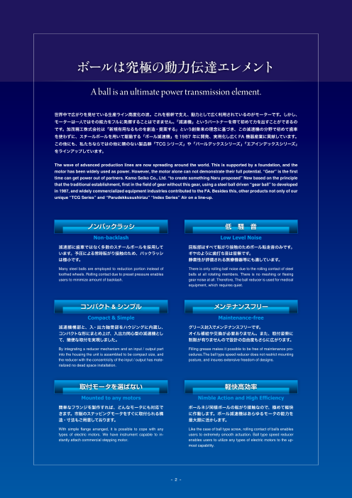
ノンバックラッシ 低 騒 音
Non-backlash Low Level Noise
減速部に歯車ではなく多数のスチールボールを採用して 回転部はすべて転がり接触のためボール転走音のみです。
います。予圧による常時転がり接触のため、バックラッシ ギヤのように歯打ち音は皆無です。
は極小です。 静粛性が評価される医療機器等にも適しています。
Many steel balls are employed to reduction portion instead of There is only rolling ball noise due to the rolling contact of steel
toothed wheels. Rolling contact due to preset pressure enables balls at all rotating members. There is no meshing or flexing
users to minimize amount of backlash. gear noise at all. Therefore, The ball reducer is used for medical
equipment, which requires quiet.
コンパクト &シンプル メンテナンスフリー
Compact & Simple Maintenance-free
減速機構部と、入・出力軸受部をハウジングに内蔵し、 グリース封入でメンテナンスフリーです。
コンパクトな形にまとめ上げ、入出力同心型の減速機とし オイル補給や交換が必要ありません。また、取付姿勢に
て、簡便な取付を実現しました。 制限が有りませんので設計の自由度もさらに広がります。
By integrating a reducer mechanism and an input / output part Filling grease makes it possible to be free of maintenance pro-
into the housing the unit is assembled to be compact size, and cedures.The ball type speed reducer does not restrict mounting
the reducer with the concentricity of the input / output has mate- posture, and insures extensive freedom of designs.
rialized no dead space installation.
取付モータを選ばない 軽快高効率
Mounted to any motors Nimble Action and High Efficiency
簡単なフランジを製作すれば、どんなモータにも対応で ボールネジ同様ボールの転がり接触なので、極めて軽快
きます。市販のステッピングモータをすぐに取付られる構 に作動します。ボール減速機はあらゆるモータの能力を
造・寸法もご用意しております。 最大限に活かします。
With simple flange arranged, it is possible to cope with any Like the case of ball type screw, rolling contact of balls enables
types of electric motors. We have instrument capable to in- users to extremely smooth actuation. Ball type speed reducer
stantly attach commercial stepping motor. enables users to utilize any types of electric motors to the up-
most capability.
- 2 - - 55 -
Page3
ボール減速機ラインアップ
ball reducer product lineup
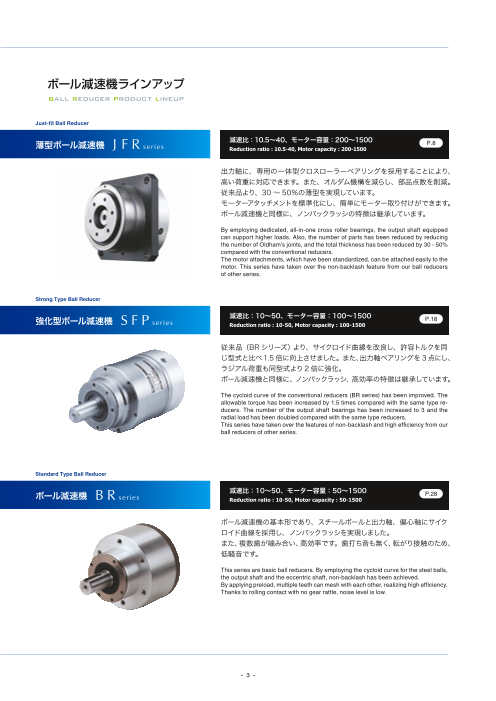
Just-fit Ball Reducer
薄型ボール減速機 J F R 減速比:10.5~40、モーター容量:200~1500
series P.8
Reduction ratio : 10.5-40, Motor capacity : 200-1500
出力軸に、専用の一体型クロスローラーベアリングを採用することにより、
高い荷重に対応できます。また、オルダム機構を減らし、部品点数を削減。
従来品より、30 ~ 50%の薄型を実現しています。
モーターアタッチメントを標準化にし、簡単にモーター取り付けができます。
ボール減速機と同様に、ノンバックラッシの特徴は継承しています。
By employing dedicated, all-in-one cross roller bearings, the output shaft equipped
can support higher loads. Also, the number of parts has been reduced by reducing
the number of Oldham’s joints, and the total thickness has been reduced by 30 - 50%
compared with the conventional reducers.
The motor attachments, which have been standardized, can be attached easily to the
motor. This series have taken over the non-backlash feature from our ball reducers
of other series.
Strong Type Ball Reducer
強化型ボール減速機 S F P 減速比:10~50、モーター容量:100~1500
series P.18
Reduction ratio : 10-50, Motor capacity : 100-1500
従来品(BR シリーズ)より、サイクロイド曲線を改良し、許容トルクを同
じ型式と比べ1.5 倍に向上させました。また、出力軸ベアリングを3 点にし、
ラジアル荷重も同型式より 2 倍に強化。
ボール減速機と同様に、ノンバックラッシ、高効率の特徴は継承しています。
The cycloid curve of the conventional reducers (BR series) has been improved. The
allowable torque has been increased by 1.5 times compared with the same type re-
ducers. The number of the output shaft bearings has been increased to 3 and the
radial load has been doubled compared with the same type reducers.
This series have taken over the features of non-backlash and high efficiency from our
ball reducers of other series.
Standard Type Ball Reducer
ボール減速機 B R 減速比:10~50、モーター容量:50~1500
series P.28
Reduction ratio : 10-50, Motor capacity : 50-1500
ボール減速機の基本形であり、スチールボールと出力軸、偏心軸にサイク
ロイド曲線を採用し、ノンバックラッシを実現しました。
また、複数歯が噛み合い、高効率です。歯打ち音も無く、転がり接触のため、
低騒音です。
This series are basic ball reducers. By employing the cycloid curve for the steel balls,
the output shaft and the eccentric shaft, non-backlash has been achieved.
By applying preload, multiple teeth can mesh with each other, realizing high efficiency.
Thanks to rolling contact with no gear rattle, noise level is low.
- 3 -
Page4
ボール減速機構&メカニズム
ball speed reduction mechanism
サイクロイドボール減速(増速)機構の原理と特徴
Principle and characteristics of cycloid ball speed reduction (increase) mechanism
原 理
PRINCIPLE
図1のように2枚の円板にボールを挟み、一方を固定、他方に偏 As shown in Fig. 1, when a ball is tucked between 2 discs while one
心量eの公転を与えると、ボールは互いの円板上に直径eの円 disc being fixed and the other disc being revolved with an eccentric
amount of e, the ball rolls over the disc insides with a circular locus of
軌跡を描いて転がります。さらに、図2のように公転円板の1公 an e in diameter. Furthermore, as shown in Fig. 2, when the unfixed
転に対し、θ度の自転を与えながら公転を与えると、ボールの軌 (revolving) disc is rotated at θº per its revolution, the ball trace draws
跡は固定円板に対し振幅eのエピ(外転)サイクロイド、公転円 an epicycloid curve (outward rolling curve) of e in amplitude over the
板に対して同振幅のハイポ(内転)サイクロイド曲線を描くこと fixed disc inside and a hypocycloid curve (inward rolling curve) over
the unfixed disc (revolving) inside (the latter is also called trochoid
になります(あるいはトロコイド曲線)。そこで発想を逆転する curve). Here, to think differently, as shown in Fig. 3, 2 discs having
と図3のようになります。すなわちー方にエピサイクロイド曲線、 a ball groove as a centroid, respectively, where one disc having an
他方にハイポサイクロイド曲線を中心軌跡としたボール溝を有す epicycloid curve ball groove and the other disc having a hypocycloid
curve ball groove, are positioned oppositely with a ball as a rolling ele-
る円板を、転動体であるボールを介して向かい合わせ、一方を ment tucked between them. When one disc is fixed and the other disc
固定、他方に公転を与えると、公転円板に2つの円板の波数の is revolved, a rotation in proportion to the difference of the wavenum-
差に比例した自転が発生するわけです。そしてこの自転を、図1 bers of the 2 discs generates on the revolving disc. And this rotation is
の円環溝を有する2つの整動板にて取り出すという機構であり、 mechanically taken out by using 2 motion-controlling plates, which is
basically equivalent to the rotation and revolution motions generated
基本的には大小円の転がり運動から発生する自転公転運動と完 by the rolling motions of 2 large and small circles.
全に等価となります。 When it comes to mesh, as shown in Fig. 4, because multiple contact
かみ合いは図4に示すようにそれぞれの曲線間にいくつもの接点 points are made between the respective curves and a ball is positioned
in a contact point, all balls are constrained inevitably and positionally
が生じ、そこにボールが位置するため、全ボールが溝によって必
(i.e., meshed) and rolling motion and torque are transmitted by the
然的に位置拘束(かみ合い)され、かつ転がり接触により転動 rolling contact of the balls.
及びトルク伝達することになります。
減 速 比
REDUCTION RATIO
減速比とは、一方の波数N、他方をN-2としたとき、N側に公 Assuming that the wavenumber of one disc is N and that of the other
転を与えたとき、i=2/Nとなり、N-2側に公転を与えたとき disc is N-2, when revolution is applied to the N side, the reduction ratio
is i = 2/N, and when revolution is applied to the N-2 side, the reduction
i=-2/(N-2)となります。つまり組み合わせの波数差は常 ratio is i = -2/(N-2). That is, the combinatorial wavenumber difference
に2であり、又、装着できるボール数は最大N-1となっています。 is always 2, and the maximum number of mountable balls is N-1.
ボール/Ball
e ピッチ円D
ボール/Ball e /Pitch c
偏心量e ircle D
Eccentricity 偏心量e
Eccentric
ity
amount e
amount e
e
A 量 A
B (偏心 ) B
(Eccentricity 円板Aの波形 円板Bの波形
図1 Fig. 1 amount) 図3 Fig. 3 Waveform of disc A Waveform of disc B
A,Bの重合線 A
θ θ Superposition line of A and B B A=10波/A = 10 waves
B=12波/B = 12 waves
速比 1/6または1/5
e e Reduction ratio 1/6 or 1/5
ピッチ円D
e
Pitch circle D
A
A B B ボールの存在位置/Existence position of ball
図2 Fig. 2 図4 Fig. 4 11カ所/11 positions
- 4 -
ピッチ円D/P
itc
h c
irc
le D
Page5
ボール減速機メカニズム
Mechanism of ball speed reducer
入力軸 固定板 オルダム板 偏心板 出力板(出力軸一体) 予圧ナット(定位置予圧型)
Input shaft Fixed plate Oldham plate Eccentric plate Output plate (integrated with output shaft) Preloading nut
オルダム用ボール 減速用ボール ハウジング (fixed position preloading type)
Oldham ball Reduction ball Housing
公転/Revolution
自転/Rotation
(ハイポ) (エピ)
偏心軸部(クランク軸) オルダム機構部 サイクロイド溝部 サイクロイド溝部 予圧作用部
Eccentric axis section (crankshaft) Oldham mechanism section (Hypocycloid) Cycloid groove section (Epicycloid) Cycloid groove section Preload acting section
偏心板に公転運動(偏心回転)を与える。 偏心板の自転運動 入力軸により公転運動し、 減速用ボールの転動を受けて 減速用ボールの挟み込み。
Applies revolution motion (eccentric) を取り除く。 減速用ボールを転動させる。 減速された自転運動を出力軸 バックラッシの除去。
to eccentric plate. Removes rotation motion Revolved by input shaft, に出力する。 Tucks reduction balls,
from eccentric plate. and rolls speed-reducing balls. Receives revolution of balls for speed and removes backlash.
reduction, and outputs speed-reduced
rotation motion to output shaft.
ボール減速機メカニズム
MECHANISM OF BALL SPEED REDUCER
入力軸
Input shaft
オルダム板(オルダム機構) 一般に歯車の噛み合っている歯は、1枚か2枚であり、例えば 100 枚の歯数を
Oldham plate (Oldham mechanism)
持つ歯車では、作用していない歯は98~ 99であり、いかにも無駄な構造になっ
ています。そこで、残っている歯に多数の歯車を配すれば噛み合う歯数も増加
し、動力伝達容量を大きく出来、装置も小型化できます。このような歯車として、
遊星歯車、調和歯車、鼓形ウォームギヤなどがありますが、その噛み合いをさ
らに多くしたものがボール減速機です。
構造としては、内外歯車による差動歯車機構の一種に類しますが、歯車の歯部
による動力伝達とは異なり、ボール(鋼球)の転動を介して動力を伝えるため、
摩擦が少なく、ほとんどのボールが運動伝達に関与しているので、小型でも伝
偏心板(減速板)
Eccentric plate 達容量が大きく、ノンバックラッシを可能にしています。
(speed-reduction plate)
In general, the number of teeth of a gear in mesh is only one or 2. For example, when
予圧ナット
Preloading nut ボール(減速用) a gear has 100 teeth, the number of teeth not in mesh is 98 – 99. This structure is
Ball
出力軸 quite a wasteful. In view of this, if many gears are arranged to operate with the remain-
(for speed reduction)
Output shaft ing teeth not in mesh of the gear, the number of teeth in mesh increases, the power
出力板(減速板)
Output plate (speed-reduction plate) transmission capacity increases, and the mechanism is downsized. Gears arranged
出力軸一体 like this include planetary gear, harmonic gear and drum-shaped worm gear. The ball
Integrated with output shaft.
reducer is one of such gear arrangements but with more number of teeth in mesh.
Structurally, the ball reducer is categorized as a type of the differential gear mecha-
nisms using the differential motion of internal and external gears. However, unlike
power transmission through gear teeth, power is transmitted through the rolling of
balls (steel balls). Therefore, because almost all balls are involved in power transmis-
sion, the ball speed reducer is featured by low friction and large transmission capacity
despite its small size, and non-backlash operation.
- 5 -
Page6
ボール減速機の応用例
application of ball reducer
引き上げ装置の駆動 インデックステーブルの駆動
Driving a pull-up unit Driving an index table
ロボットのアーム軸駆動 走行軸の駆動(イラストは TCG との組合せ)
Driving a robot arm shaft Driving a traveling shaft (combined with the TCG in illustration)
- 6 -
Page7
AGV 車輪の駆動 ボールねじの駆動
Driving an AGV wheel Driving a ball screw
工作機械の ATC 駆動 ベルトコンベアーの駆動部
ATC drive unit for machine tools Driving a belt conveyor
- 7 -
Page8
薄型ボール減速機
Just-fit Ball Reducer
J FR Series
構造図 Structual Drawing
❺ 入力軸/Input Shaft
❸ スチールボール/Steel Ball
❻ 固定板/Fixed Disk
❶ 出力軸/Output Shaft
❷ クロスローラーベアリング
Cross Roller Bearing
❼ モータアタッチメント
❹ 偏心板/Eccentric Disk Motor Attachment
Page9
JFR Series JFRシリーズ
J FR S e r i e s
JFR仕様 JFR Specifications
型 式 Model JFR60 JFR90 JFR120
減速比 Reduction ratio 10.5 15 20 30 10.5 15 20 30 40 10.5 15 20 30 40
回転方向(入力軸に対する出力軸の回転方向)
Rotation directio(n Rotation direction of output shaft correlated 逆方向 Reverse 逆方向 Reverse 逆方向 Reverse
to input shaft)
許容定格トルク N・m 8.5 9.4 10.4 10.5 25.9 28.5 30.8 30.5 29 63.4 70 81.4 77.5 72.3
Allowable rated torque
加速時ピークトルク N・m 25.5 27.9 31.2 29.6 77.7 81 81.7 91.5 87 190.2 210 244.2 232.5 198.5
Acceleration peak torque
瞬時最大トルク N・m 50 180 450
Max. instantaneous torque
許容平均入力回転数 rpm 3000 3000 3000
Allowable average number of input revolutions
最高入力回転数 rpm 4500 4500 4500
Max input rpm
推奨モータ容量 W 200 400 750
Recommendable motor capacity
入力軸 出力軸U型タイプ
換算慣性 0.152 0.153 0.154 0.155 0.655 0.659 0.667 0.672 0.677 2.66 2.66 2.69 2.71 2.74
Output shaft U-shaped type
モーメント ×10-4kg・㎡
Inertia moment
converted to 出力軸S型タイプ 0.154 0.154 0.155 0.155 0.664 0.664 0.669 0.673 0.677 2.72 2.69 2.70 2.72 2.75
input shaft Output shaft S-shaped type
14 19 24
11 16 22
入力軸穴径 8 14 19
㎜
Input shaft hole diameter 11 16
10 14
8
※1 連続回転にて使用される場合は弊社にご相談ください。 When you intend to use in continuous revolution, please consult us.
※2 許容慣性モーメント荷重等の仕様についてはP.48-49、減速機・モータ取付要領についてはP.50をご参照ください。
Please refer to P.48-49 for specifications such as allowable moment load, and P.50 for Reducer/motor installation instruction.
型式表示 Model Indication
JFR型番 JFR model No.
JFR A - - -
出力軸オプション(S型のみ):A…標準、B…キー溝付き、
C…先端タップ、D…B+C
Output shaft option( only for S type) : A…Standard, B…With keyway, C…Tip tap, D…B+C
モータ情報:P14~18までの「モータ・減速機対応表」の5
桁の数字を入力して下さい。
Motor information : Input the 5-digit number referring to the “Motor and Reduction
Ratio Correspondence Table” on P. 14 - 18.
減速比:10.5、15、20、30、40 (60型は除く)
Reduction ratio : 10.5, 15, 20, 30, 40( Excluding 60 type)
入力軸形状:C Input shaft shape : C
出力軸形状:U、S Output shaft shape : U, S
枠番:60、90、120 Frame number : 60, 90, 120
- 9 -
Page10
JFRシリーズ JFR Series
外形寸法図 Outside Dimensional Drawing
JFR60
出力軸U型 Output shaft U type
4×φ6
4×J
6×M4 深さ7
6×M4 Depth 7
P.C.DI.
32 95
3
4 12 D M4
(C) 80
(28) 10 B
(A)
出力軸S型 Output shaft S type
5
C0
. 4
R0
.
40 12 D
50 (C)
(78) 10 B
(AA)
寸 法 表 Dimension Table
型 式 A AA B C D φF φG I J 質量 Mass weight
Model kg
A01 55 105 17 27 5 8 30 φ46 出力軸U型
M4× 8 Output shaft U type
B01 11 0.9
出力軸S型
57 107 19 32 7 50 φ70 Output shaft S type
B02 14 M5×10 1.1
A :出力軸U型全長 Overall length of output shaft U type
AA:出力軸S型全長 Overall length of output shaft S type
- 10 -
φ60h7
φ59
(φ42.3)
φ42 φ60h7
φ59
φ20
(φ42.3)
φ16h7
φ22H7
φFH8
φGE7
φ79
φFH8
φGE7
φ79
80
Page11
JFR Series JFRシリーズ
外形寸法図 Outside Dimensional Drawing
JFR90
出力軸U型 Output shaft U type
6-M5×10 4-J 4-φ9
I P.C
.D.1
30P.C.D.
P.C.D
.46
5
M5
5 15 D
(C) □110
(38) 12 B
(A)
出力軸S型 Output shaft S type
C0
.5
50 15 D
61 (C)
(99) 12 B
(AA)
寸 法 表 Dimension Table
型 式 A AA B C D φF φG I J 質量 Mass weight
Model kg
26 8
C01 36 □50
39 10 M4× 8
C02 11・14 出力軸U型
50 φ70 Output shaft U type
C03 39 M5×10
70 131 20 5 14 2.8
C04 60 □70 M6×12 出力軸S型
Output shaft S type
C05 42 19 M5×10 3.2
39 14 70 φ90
C06 M6×12
42 16・19
出力軸U型
Output shaft U type
D01 11・14 M5×10
75 136 25 44 10 70 φ90 2.9
出力軸S型
Output shaft S type
D02 14 M6×12 3.3
A :出力軸U型全長 Overall length of output shaft U type
AA:出力軸S型全長 Overall length of output shaft S type
- 11 -
φ90h7
φ88
(63.5)
φ60 φ90h7
φ25 φ88
φ20h7 (φ63.5)
φ30H7
φF H8
φG E7
φ109
φF H8
φG E7
φ109
Page12
JFRシリーズ JFR Series
外形寸法図 Outside Dimensional Drawing
JFR120
出力軸U型 Output shaft U type
8-M6×12 4-J 4-φ11
.65 P.C.
P.C
.D DI. .
P.C
.D 1
90
5
M6
6 20 D
(C) □165
(51) 15 B
(A)
出力軸S型 Output shaft S type
C1
80 20 D
95 (C)
(146) 15 B
(AA)
寸 法 表 Dimension Table
型 式 A AA B C D φF φG I J 質量 Mass weight
Model kg
E01 M4× 8
96 191 30 44 10 50 φ70
14 出力軸U型
E02 M5×10 Output shaft U type
E03 39 60 □70 M6×12 7.4
E04 55 19 M5×10 出力軸S型
91 186 25 5
39 14 70 φ90 Output shaft S type
E05 M6×12 8.9
55 16・19
F01 70 φ90 M5×10
44 14
F02 80 φ100
60 16・19 M6×12 出力軸U型
F03 68 24 Output shaft U type
96 191 30 60 16・19 95 φ115 7.7
F04 出力軸S型
68 24
M8×16 Output shaft S type
60 16・19 9.2
F05 110 φ145
68 22・24
F06 44 14 70 φ90 M6×12
10 出力軸U型
Output shaft U type
8.0
G01 101 196 35 73 22 出力軸S型
Output shaft S type
9.5
110 φ145 M8×16
出力軸U型
Output shaft U type
H01 106 201 40 70 19 8.3
出力軸S型
Output shaft S type
9.8
A :出力軸U型全長 Overall length of output shaft U type
AA:出力軸S型全長 Overall length of output shaft S type
- 12 -
φ120h7
φ117
(φ85.5)
φ85 φ120h7
φ40 φ117
φ30h7
(φ85.5)
φ45H7
φF H8
φG E7
φ158
φF H8
φG E7
φ158
Page13
JFR Series JFRシリーズ
出力軸オプション Output Shaft Option
オプションB(キー溝付) オプションC(先端タップ付) オプションD(キー溝・先端タップ付)
Option code B(Keyway) Option code C(Tip tap) Option code D(Keyway・tip tap)
b P9 b P9
L L
T T
L・b・hはオプションB・Dのみ、TはオプションC・Dのみ
L & b & h is available in option code B & D only , T has option code C & D only.
型 式 L b h T
Model
JFR60 36 5 3 M5深サ10 M5 Depth 10
JFR90 45 6 3.5 M6深サ12 M6 Depth 12
JFR120 70 8 4 M8深サ16 M8 Depth 16
- 13 -
h +0.2 0
+0.2
h 0
Page14
JFRシリーズ JFR Series
モータ・減速機対応表 Motor and Reduction Ratio Correspondence Table
モータ・減速機対応表は簡易表です。必ず型式選定計算を行ってください。グレー表示の型式は、減速機加速時ピークトルクを超
えないようにご使用ください。掲載されていないモータ型式については弊社にお問い合わせください。
Since the Motor and Reduction Ratio Correspondence Table is a simplified presentation, be sure to make a model selecting calculation. Please use so that the peak torque
during acceleration of the reducer is not exceeded about the motor mounting Number in gray colour. For any motor model not listed here, please consult us.
Panasonic
の型式は減速機加速時ピークトルクを超えないようにご注意ください。
Please be careful so that the peak torque during acceleration of the speed reducer is not exceeded about the motor mounting Number in gray colour.
JFR型式・減速比 JFR model · Reduction ratio
モータ型式
Moter Model JFR60 JFR90 JFR120
10.5 15 20 30 10.5 15 20 30 40 10.5 15 20 30 40
02 B0111 B0111 B0111 B0111 C0211 C0211 C0211 C0211 C0211
04 C0214 C0214 C0214 C0214 C0214 E0114 E0114 E0114 E0114 E0114
08 C0519 C0519 C0519 C0519 C0519 E0419 E0419 E0419 E0419 E0419
MSMF
09 C0519 C0519 C0519 C0519 C0519 E0419 E0419 E0419 E0419 E0419
10 F0419 F0419 F0419 F0419 F0419
15 F0419 F0419 F0419 F0419 F0419
02 D0111 D0111 D0111 D0111 D0111
MQMF
04 D0114 D0114 D0114 D0114 D0114 F0114 F0114 F0114 F0114 F0114
02 B0111 B0111 B0111 B0111 C0211 C0211 C0211 C0211 C0211
A6 04 C0214 C0214 C0214 C0214 C0214 E0114 E0114 E0114 E0114 E0114
08 C0519 C0519 C0519 C0519 C0519 E0419 E0419 E0419 E0419 E0419
MHMF
09 C0519 C0519 C0519 C0519 C0519 E0419 E0419 E0419 E0419 E0419
10 G0122 G0122 G0122 G0122 G0122
15 G0122 G0122 G0122 G0122 G0122
10 F0522 F0522 F0522 F0522 F0522
MDMF
15 F0522 F0522 F0522 F0522 F0522
09 F0522 F0522 F0522 F0522 F0522
MGMF 13 F0522 F0522 F0522 F0522 F0522
18 F0522 F0522 F0522 F0522 F0522
02 B0111 B0111 B0111 B0111 C0211 C0211 C0211 C0211 C0211
04 C0214 C0214 C0214 C0214 C0214 E0114 E0114 E0114 E0114 E0114
MSME 08 C0519 C0519 C0519 C0519 C0519 E0419 E0419 E0419 E0419 E0419
10 F0419 F0419 F0419 F0419 F0419
15 F0419 F0419 F0419 F0419 F0419
02 B0111 B0111 B0111 B0111 C0211 C0211 C0211 C0211 C0211
MSMD 04 C0214 C0214 C0214 C0214 C0214 E0114 E0114 E0114 E0114 E0114
08 C0519 C0519 C0519 C0519 C0519 E0419 E0419 E0419 E0419 E0419
A5
10 F0522 F0522 F0522 F0522 F0522
MDME
15 F0522 F0522 F0522 F0522 F0522
MGME 09 G0122 G0122 G0122 G0122 G0122
10 G0122 G0122 G0122 G0122 G0122
MHME
15 G0122 G0122 G0122 G0122 G0122
02 B0111 B0111 B0111 B0111 C0211 C0211 C0211 C0211 C0211
MHMD 04 C0214 C0214 C0214 C0214 C0214 E0114 E0114 E0114 E0114 E0114
08 C0519 C0519 C0519 C0519 C0519 E0419 E0419 E0419 E0419 E0419
※オイルシール付は除きます。 Excluding motor models which set the shaft part with the oil seal.
- 14 -
Page15
JFR Series JFRシリーズ
三菱電機 Mitsubishi Electric
の型式は減速機加速時ピークトルクを超えないようにご注意ください。
Please be careful so that the peak torque during acceleration of the speed reducer is not exceeded about the motor mounting Number in gray colour.
JFR型式・減速比 JFR model · Reduction ratio
モータ型式
Moter Model JFR60 JFR90 JFR120
10.5 15 20 30 10.5 15 20 30 40 10.5 15 20 30 40
1M3W A0108 A0108 A0108 A0108
23W B0214 B0214 B0214 B0214 C0314 C0314 C0314 C0314 C0314 E0214 E0214 E0214 E0214 E0214
43W B0214 B0214 B0214 B0214 C0314 C0314 C0314 C0314 C0314 E0214 E0214 E0214 E0214 E0214
63W B0214 B0214 B0214 B0214 C0314 C0314 C0314 C0314 C0314 E0214 E0214 E0214 E0214 E0214
23UW C0614 C0614 C0614 C0614 C0614 E0514 E0514 E0514 E0514 E0514
HK-KT 43UW C0614 C0614 C0614 C0614 C0614 E0514 E0514 E0514 E0514 E0514
7M3W C0619 C0619 C0619 C0619 C0619 E0519 E0519 E0519 E0519 E0519
103W C0619 C0619 C0619 C0619 C0619 E0519 E0519 E0519 E0519 E0519
J5 7M3UW F0219 F0219 F0219 F0219 F0219
103UW F0219 F0219 F0219 F0219 F0219
153W F0219 F0219 F0219 F0219 F0219
52W F0524 F0524 F0524 F0524 F0524
102W F0524 F0524 F0524 F0524 F0524
524W F0524 F0524 F0524 F0524 F0524
HK-ST
1024W F0524 F0524 F0524 F0524 F0524
1724W F0524 F0524 F0524 F0524 F0524
2024AW F0524 F0524 F0524 F0524 F0524
23 B0214 B0214 B0214 B0214 C0314 C0314 C0314 C0314 C0314 E0214 E0214 E0214 E0214 E0214
HG-KR 43 B0214 B0214 B0214 B0214 C0314 C0314 C0314 C0314 C0314 E0214 E0214 E0214 E0214 E0214
73 C0619 C0619 C0619 C0619 C0619 E0519 E0519 E0519 E0519 E0519
23 B0214 B0214 B0214 B0214 C0314 C0314 C0314 C0314 C0314 E0214 E0214 E0214 E0214 E0214
HG-MR 43 B0214 B0214 B0214 B0214 C0314 C0314 C0314 C0314 C0314 E0214 E0214 E0214 E0214 E0214
73 C0619 C0619 C0619 C0619 C0619 E0519 E0519 E0519 E0519 E0519
J4 51 F0524 F0524 F0524 F0524 F0524
81 F0524 F0524 F0524 F0524 F0524
HG-SR 52 F0524 F0524 F0524 F0524 F0524
102 F0524 F0524 F0524 F0524 F0524
152 F0524 F0524 F0524 F0524 F0524
103 F0424 F0424 F0424 F0424 F0424
HG-RR
153 F0424 F0424 F0424 F0424 F0424
- 15 -
Page16
JFRシリーズ JFR Series
モータ・減速機対応表 Motor and Reduction Ratio Correspondence Table
安川電機 Yaskawa Electric
の型式は減速機加速時ピークトルクを超えないようにご注意ください。
Please be careful so that the peak torque during acceleration of the speed reducer is not exceeded about the motor mounting Number in gray colour.
JFR型式・減速比 JFR model · Reduction ratio
モータ型式
Moter Model JFR60 JFR90 JFR120
10.5 15 20 30 10.5 15 20 30 40 10.5 15 20 30 40
C2A A0108 A0108 A0108 A0108
02A B0214 B0214 B0214 B0214 C0314 C0314 C0314 C0314 C0314 E0214 E0214 E0214 E0214 E0214
SGMXJ 04A B0214 B0214 B0214 B0214 C0314 C0314 C0314 C0314 C0314 E0214 E0214 E0214 E0214 E0214
06A B0214 B0214 B0214 B0214 C0314 C0314 C0314 C0314 C0314 E0214 E0214 E0214 E0214 E0214
08A C0619 C0619 C0619 C0619 C0619 E0519 E0519 E0519 E0519 E0519
C2A A0108 A0108 A0108 A0108
02A B0214 B0214 B0214 B0214 C0314 C0314 C0314 C0314 C0314 E0214 E0214 E0214 E0214 E0214
∑-X
04A B0214 B0214 B0214 B0214 C0314 C0314 C0314 C0314 C0314 E0214 E0214 E0214 E0214 E0214
SGMXA
06A B0214 B0214 B0214 B0214 C0314 C0314 C0314 C0314 C0314 E0214 E0214 E0214 E0214 E0214
08A C0619 C0619 C0619 C0619 C0619 E0519 E0519 E0519 E0519 E0519
10A C0619 C0619 C0619 C0619 C0619 E0519 E0519 E0519 E0519 E0519
09A F0524 F0524 F0524 F0524 F0524
SGMXG 13A F0524 F0524 F0524 F0524 F0524
20A F0524 F0524 F0524 F0524 F0524
C2A A0108 A0108 A0108 A0108
02A B0214 B0214 B0214 B0214 C0314 C0314 C0314 C0314 C0314 E0214 E0214 E0214 E0214 E0214
SGM7J 04A B0214 B0214 B0214 B0214 C0314 C0314 C0314 C0314 C0314 E0214 E0214 E0214 E0214 E0214
06A B0214 B0214 B0214 B0214 C0314 C0314 C0314 C0314 C0314 E0214 E0214 E0214 E0214 E0214
08A C0619 C0619 C0619 C0619 C0619 E0519 E0519 E0519 E0519 E0519
C2A A0108 A0108 A0108 A0108
02A B0214 B0214 B0214 B0214 C0314 C0314 C0314 C0314 C0314 E0214 E0214 E0214 E0214 E0214
04A B0214 B0214 B0214 B0214 C0314 C0314 C0314 C0314 C0314 E0214 E0214 E0214 E0214 E0214
SGM7A 06A B0214 B0214 B0214 B0214 C0314 C0314 C0314 C0314 C0314 E0214 E0214 E0214 E0214 E0214
∑-7 08A C0619 C0619 C0619 C0619 C0619 E0519 E0519 E0519 E0519 E0519
10A C0619 C0619 C0619 C0619 C0619 E0519 E0519 E0519 E0519 E0519
15A F0324 F0324 F0324 F0324 F0324
02A C0614 C0614 C0614 C0614 C0614 E0514 E0514 E0514 E0514 E0514
SGM7P
04A C0614 C0614 C0614 C0614 C0614 E0514 E0514 E0514 E0514 E0514
03A F0216 F0216 F0216 F0216 F0216
05A F0216 F0216 F0216 F0216 F0216
SGM7G 09A F0524 F0524 F0524 F0524 F0524
13A F0524 F0524 F0524 F0524 F0524
20A F0524 F0524 F0524 F0524 F0524
※オイルシール付は除きます。 Excluding motor models which set the shaft part with the oil seal.
- 16 -
Page17
JFR Series JFRシリーズ
富士電機 Fuji Electric
の型式は減速機加速時ピークトルクを超えないようにご注意ください。
Please be careful so that the peak torque during acceleration of the speed reducer is not exceeded about the motor mounting Number in gray colour.
JFR型式・減速比 JFR model · Reduction ratio
モータ型式
Moter Model JFR60 JFR90 JFR120
10.5 15 20 30 10.5 15 20 30 40 10.5 15 20 30 40
201 B0214 B0214 B0214 B0214 C0314 C0314 C0314 C0314 C0314 E0214 E0214 E0214 E0214 E0214
401 B0214 B0214 B0214 B0214 C0314 C0314 C0314 C0314 C0314 E0214 E0214 E0214 E0214 E0214
GYS 751 C0616 C0616 C0616 C0616 C0616 E0516 E0516 E0516 E0516 E0516
102 F0424 F0424 F0424 F0424 F0424
152 F0424 F0424 F0424 F0424 F0424
201 C0614 C0614 C0614 C0614 C0614 E0514 E0514 E0514 E0514 E0514
401 C0614 C0614 C0614 C0614 C0614 E0514 E0514 E0514 E0514 E0514
GYC 751 F0416 F0416 F0416 F0416 F0416
102 F0524 F0524 F0524 F0524 F0524
152 F0524 F0524 F0524 F0524 F0524
501C F0519 F0519 F0519 F0519 F0519
751C F0519 F0519 F0519 F0519 F0519
GYG
102C F0522 F0522 F0522 F0522 F0522
152C F0522 F0522 F0522 F0522 F0522
201 B0214 B0214 B0214 B0214 C0314 C0314 C0314 C0314 C0314 E0214 E0214 E0214 E0214 E0214
GYB 401 B0214 B0214 B0214 B0214 C0314 C0314 C0314 C0314 C0314 E0214 E0214 E0214 E0214 E0214
751 C0619 C0619 C0619 C0619 C0619 E0519 E0519 E0519 E0519 E0519
キーエンス KEYENCE
の型式は減速機加速時ピークトルクを超えないようにご注意ください。
Please be careful so that the peak torque during acceleration of the speed reducer is not exceeded about the motor mounting Number in gray colour.
JFR型式・減速比 JFR model · Reduction ratio
モータ型式
Moter Model JFR60 JFR90 JFR120
10.5 15 20 30 10.5 15 20 30 40 10.5 15 20 30 40
020 B0214 B0214 B0214 B0214 C0314 C0314 C0314 C0314 C0314 E0214 E0214 E0214 E0214 E0214
040 B0214 B0214 B0214 B0214 C0314 C0314 C0314 C0314 C0314 E0214 E0214 E0214 E0214 E0214
075 C0619 C0619 C0619 C0619 C0619 E0519 E0519 E0519 E0519 E0519
SV2
100 F0524 F0524 F0524 F0524 F0524
150 F0524 F0524 F0524 F0524 F0524
200 F0524 F0524 F0524 F0524 F0524
オムロン OMRON
の型式は減速機加速時ピークトルクを超えないようにご注意ください。
Please be careful so that the peak torque during acceleration of the speed reducer is not exceeded about the motor mounting Number in gray colour.
JFR型式・減速比 JFR model · Reduction ratio
モータ型式
Moter Model JFR60 JFR90 JFR120
10.5 15 20 30 10.5 15 20 30 40 10.5 15 20 30 40
1M20030 B0111 B0111 B0111 B0111 C0211 C0211 C0211 C0211 C0211
1M40030 C0214 C0214 C0214 C0214 C0214 E0114 E0114 E0114 E0114 E0114
1M75030 C0519 C0519 C0519 C0519 C0519 E0419 E0419 E0419 E0419 E0419
1M1K020 F0522 F0522 F0522 F0522 F0522
1M1K520 F0522 F0522 F0522 F0522 F0522
1L1K030 F0419 F0419 F0419 F0419 F0419
1S R88M-
1L1K530 F0419 F0419 F0419 F0419 F0419
1AM20030 B0111 B0111 B0111 B0111 C0211 C0211 C0211 C0211 C0211
1AM40030 C0214 C0214 C0214 C0214 C0214 E0114 E0114 E0114 E0114 E0114
1AM75030 C0519 C0519 C0519 C0519 C0519 E0419 E0419 E0419 E0419 E0419
1AL1K030 F0419 F0419 F0419 F0419 F0419
1AL1K530 F0419 F0419 F0419 F0419 F0419
K20030 B0111 B0111 B0111 B0111 C0211 C0211 C0211 C0211 C0211
K40030 C0214 C0214 C0214 C0214 C0214 E0114 E0114 E0114 E0114 E0114
K75030 C0519 C0519 C0519 C0519 C0519 E0419 E0419 E0419 E0419 E0419
G5 R88M- K1K030 F0419 F0419 F0419 F0419 F0419
K1K530 F0419 F0419 F0419 F0419 F0419
K1K020 F0522 F0522 F0522 F0522 F0522
K1K520 F0522 F0522 F0522 F0522 F0522
- 17 -
Page18
強化型ボール減速機
Strong Type Ball Reducer
S F P Series
構造図 Structual Drawing
入力軸/Input shaft
スチールボール/Steel ball
出力軸/Output shaft
モータアタッチメント/Motor mounting plate
固定板/Fixed disc
オルダム板/Oldham disc
偏心板/Eccentric disc
Page19
SFP Series SFPシリーズ
SFP S e r i e s
SFP-S型仕様 SFP-S Specifications
型 式 Model SFP70SCA SFP85SCA SFP100SCA SFP125SCA
減速比 Reduction ratio 8 10 20 30 10 20 30 40 10 20 30 40 10 20 30 40 50
回転方向(入力軸に対する出力軸の回転方向)
Rotation directio( 逆方向 同方向 逆方向
n 同方向 逆方向 逆
Rotation direction of output shaft correlated Forward 同方向 方向
Forward 同方向 Forward
to input shaft) Reverse Forward Reverse Reverse Reverse
許容定格トルク
Allowable rated torque N・m 10 11 12 12.8 25.5 28.4 26.2 26 48.8 56 56 56 90 96.5 96.5 98.8 99.2
加速時ピークトルク
Max. instantaneous torque N・m 20 21.2 22 22.6 42 48.3 44.6 44.2 78 89.4 95.2 95.2 155 168.9 168.9 172.9 173.6
瞬時最大トルク
Max. instantaneous torque N・m 40 70 85 130 160 240 270
出力軸許容ラジアル荷重※1
Allowable radial load at output shaft N 500 1000 1500 2000
出力軸許容スラスト荷重※1
Allowable thrust load at output shaft N 200 400 600 1000
許容平均入力回転数
Allowable average number of input revolutions rpm 3000 3000 2000 2000
最高入力回転数
Max input rpm rpm 4500 4500 4000 4000
入力軸換算慣性モーメント
Inertia moment converted to input shaft ×10-4kg・㎡ 0.149 0.149 0.159 0.161 0.484 0.431 0.414 0.406 1.58 1.43 1.38 1.36 3.45 2.98 2.86 2.81 2.78
推奨モータ容量
Recommendable motor capacity W 200 200 100 100 400 200 200 100 750 400 400 200 1500 750 750 400 400
14 14 19 24
11 11 16 22
入力軸穴径
Input shaft hole diameter ㎜ 8 8 14 19
11 16
14
※1 許容ラジアル荷重は軸方向の負荷位置が各軸の先端の場合となります。
This allowable radial load value is realized when the load positioned in the axial direction is the figure at top of shaft.
※2 減速機・モータ取付要領についてはP.50をご参照ください。 Please refer to P.50 for Reducer/motor installation instruction.
型式表示 Model Indication
SFP型式(S型) Model SFP (Type S)
SFP S C A - - - 00
取付プレート:F …取付プレート有、0…取付プレート無
Mounting plate: F … Available, 0 … None
出力軸オプション:A …標準、B…キー溝付、
C…先端タップ、D…B+C
Output shaft option: A … Standard, B … With keyway,
C … Tip tapped, D … B+C
出力軸径:1 6…SFP70型
20…SFP85型
25…SFP100型
30…SFP125型
Output shaft diameter: 16 … Model SFP70
20 … Model SFP85
25 … Model SFP100
30 … Model SFP125
モータ取付記号:例 …A0108(5桁の数字を記入)
※モ ータアタッチメントなしの場合は000□□の5桁
減速比:8(70型のみ)、10、20、30、40(70型以外)、 の数字を入力
50(125型のみ) 入力穴径:8~24
Reduction ratio: ※ モータ・減速機対応表P23~27を参照
8( 70 only), 10, 20, 30, 40( Excluding 70 type), 50( 125 only) Motor mounting code: Example … A010(8 Enter 5-digit number.)
リビジョン Revision ※When no motor attachment is used, enter 5-digit number of 000□□.
Input hole diameter: 8 – 24
入力軸形状:C Input shaft shape: C ※For Motor and Reduction Ratio Corresponding Table, refer to P. 23 – 27.
出力軸形状:S…シャフトタイプ
Output shaft shape: S … Shaft type
枠番:70、85、100、125 Frame number : 70, 85, 100, 125
- 19 -
Page20
SFPシリーズ SFP Series
外形寸法図 Outside Dimensional Drawing
SFP70
6×M4 深さ10
10 4.5 6×M4 Depth 10 12.5
6×M4 深さ8 6×4.3キリ
6×M4 Depth 8 6×4.3 Dril thru M4 4×J
6 .
3 63 P.C.DI
3 8
CA
8 (CB)
28 (20) (11)
(49) 63.5 21
(133.5)
寸 法 表 Dimension Table
型 式 CA CB E F G I J 質量 Mass weight
Model kg
A01 22 48
M3×6
A02 72 8 45
23 33 30
A03 46
8 M4×8 1.4
B01
28 38 11
78 50 70
23 33 8
B02 M5×10
28 38 14
※モータアタッチメントがない場合の質量は、1.3kg Mass with no motor attachment: 1.3kg
SFP85
6×φ5.3
6×M5 深さ10
6×M5 深さ10 Depth 10 11 c d
80 Depth 10
4-J I
P.C
.D.
e
4 b 8
CA
10 (CB)
36 (29) (19.5)
(67) 68 30
(165)
寸 法 表 Dimension Table
型 式 CA CB E F G I J a b c d e 質量 Mass weight
Model kg
C01 45 M3×6
30
C02 23 33.5 8 46 30 10 5 10 M4
M4×8
C03 88
28 38.5 11・14 40 12 6 14 M5
50 70 3.6
23 33.5 8 30 10 5 10 M4
C04
14 M5×10
D01 28 38.5 11・14 40 12 6 14 M5
98 70 90
D02 14 M6×12
※モータアタッチメントがない場合の質量は、3.2kg Mass with no motor attachment: 3.2kg
- 20 -
φ88
φ68h7 φ72
φ20h6 φ52h7
φ16h6
φF H8 φFH8
a φ50h7
φ50h7 φGE7
φG E7 φE
φE
77