


ある時は高送りで、そしてまたある時は高切り込みで。
関連メディア
このカタログについて
| ドキュメント名 | アルファ高送りラジアスミル TD6N形 |
|---|---|
| ドキュメント種別 | 製品カタログ |
| ファイルサイズ | 3.6Mb |
| 取り扱い企業 | 株式会社MOLDINO (この企業の取り扱いカタログ一覧) |
この企業の関連カタログ

このカタログの内容
Page1
TD6N type
アルファ 高送りラジアスミル TD6N形
Radius Mill TD6N type
MOLDINO Tool Engineering, Ltd.
New Produc t News No.1902-3 2020-10
Page2
高送りの新定番
New standard tools for high-feed cutting
独自のR状刃形が進化、 JM4160 加工用途 Applications
JS4030
更なる高能率加工を実現する。 JP4120
ステンレス鋼 一般構造用鋼 炭素鋼 プリハードン鋼 焼入れ鋼 鋳鉄
Unique R-shaped cutting edge has evolved to 200HB以下 合金鋼 合金鋼 45~50HRC 荒
realize further high- efficiency machining. Stainless steel Mild Steel 35HRC以下 35~45HRC Hardened steel Cast iron 両面使えて(200HB or less) Carbon steel Pre-hardened steel (45~50HRC) Roughing 経済的
Alloy steel Alloy steel Economical
(35HRC or less) (35~45HRC) double-sided
multi-corner inserts
様々なアプリケーションでの
課題を解決します。 取り代が不均一な鋳肌面の加工では、
Resolves issues in various applications. 課題Issue 断続切削になるので工具破損が起こりやすく
困っている。
課題 高送り加工では、形状や加工部位によって 02 Machining of the cast surface with uneven machining allowance should be interrupted
Issue cutting, so it is apt to cause tool breakage.突発的な工具破損が発生する。
01 加工条件の設定を下げると、加工時間が長くなってしまう。In high-feed cutting, sudden tool breakage occurs due to the shape and machining section 課題解決のご提案!
of work-piece. If the cutting condition is lowered, machining time should be longer.
Proposed solutions
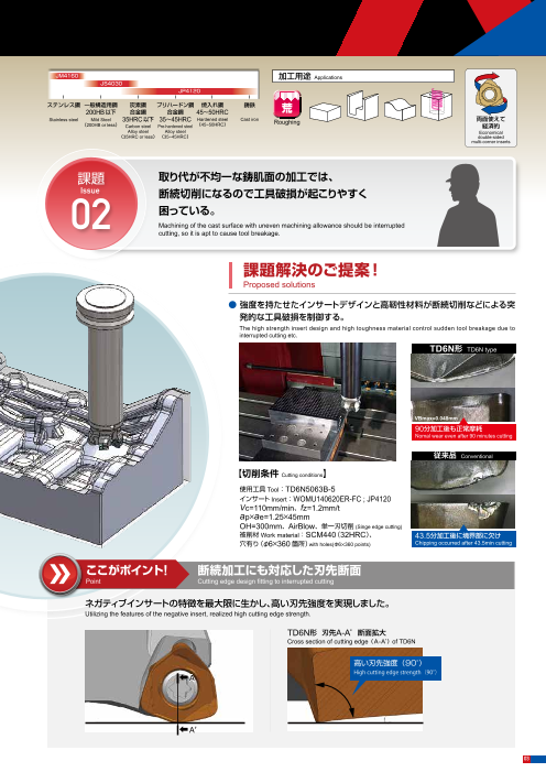
● 強度を持たせたインサートデザインと高靭性材料が断続切削などによる突
課題解決のご提案! 発的な工具破損を制御する。
Proposed solutions The high strength insert design and high toughness material control sudden tool breakage due to interrupted cutting etc.
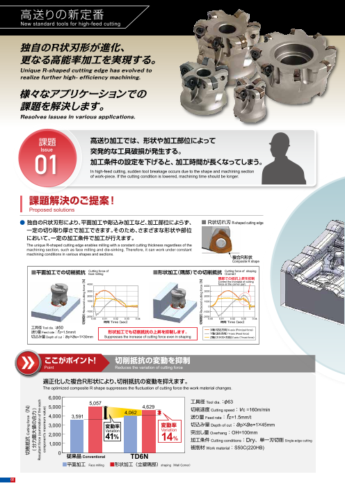
● 独自のR状刃形により、平面加工や彫込み加工など、加工部位によらず、 ■ R状切れ刃 R-shaped cutting edge TD6N形 TD6N type
一定の切り取り厚さで加工できます。そのため、さまざまな形状や部位
において、一定の加工条件で加工が行えます。
The unique R-shaped cutting edge enables milling with a constant cutting thickness regardless of the
machining section, such as face milling and die-sinking. Therefore, it can work under constant
machining conditions in various shapes and sections.
複合R形状
Composite R shape
VBmax=0.048mm
■平面加工での切削抵抗 Cutting force of ■形状加工(隅部)での切削抵抗 Cutting force of shaping 90分加工後も正常摩耗face milling (Corner) Nomal wear even after 90 minutes cutting
隅部での抵抗上昇を抑制
Control the increase of cutting
4000 force at the corner part.
4000 従来品 Conventional
3000 3000
2000 2000
1000 1000 【切削条件 Cutting conditions】
0 0
-1000 使用工具 Tool:-1000 TD6N5063B-5
-2000 -2000 インサート Insert:WOMU140620ER-FC ; JP4120
0.00 0.01 0.02 0.03 0.04 0.00 0.01 0.02 0.03 0.04
時間 Time[ sec] 時間 Time[ sec] Vc=110mm/min、fz=1.2mm/t
工具径 Tool dia.:φ50 ap×ae=1.25×45mm
送り量 :f 形状加工でも切削抵抗の上昇を抑制します。 X軸(切込方向)X-axis (Principal force)Feed rate z=1.5mm/t Y軸(送り方向) Y-axis (Feed force) OH=300mm、AirBlow、単一刃切削 (Singe edge cutting)
切込み量 Depth of cut:ap×ae=1×30mm Suppresses the increase of cutting force even in shaping Z軸(スラスト方向)Z-axis (Thrust force) 被削材Work material:SCM440(32HRC)、 43.5分加工後に境界部に欠け
穴有り(φ6×360箇所)with holes(Φ6×360 points) Chipping occurred after 43.5min cutting
ここがポイント! 切削抵抗の変動を抑制 ここがポイント! 断続加工にも対応した刃先断面
Point Reduces the variation of cutting force Point Cutting edge design fitting to interrupted cutting
適正化した複合R形状により、切削抵抗の変動を抑えます。 ネガティブインサートの特徴を最大限に生かし、高い刃先強度を実現しました。
The optimized composite R shape suppresses the fluctuation of cutting force the work material changes. Utilizing the features of the negative insert, realized high cutting edge strength.
6,000
5,057 工具径 Tool dia.:φ63 TD6N形 刃先A-A’断面拡大
5,000 4,629 Cross section of cutting edge(A-A’)of TD6N
4,062 切削速度 Cutting speed:vc =160m/min
4,000 3,591 送り量 Feed rate: fz=1.5mm/t 高い刃先強度(90°)
3,000 変動率 変動率 切込み量 Depth of cut:ap×ae=1×45mm High cutting edge strength(90°)
Variation Variation ⬅A
2,000 41 14 突出し量 Overhang:OH=100mm% % 加工条件 Cutting conditions:Dry、単一刃切削 Single-edge cutting
1,000
被削材 Work material:S50C(220HB)
0 従来品 Conventional TD6N
■平面加工 Face milling ■形状加工(立壁隅部) ⬅A’shaping(Wall Corner)
02
切削抵抗 Cutting force(N)
( 分力最大値の合力 )
Resultant force (summation of the each
component's maximum value)
切削抵抗 Reduced cutting force[ N]
切削抵抗 Reduced cutting force[ N]
Page3
高送りの新定番
New standard tools for high-feed cutting
独自のR状刃形が進化、 JM4160 加工用途 Applications
JS4030
更なる高能率加工を実現する。 JP4120
ステンレス鋼 一般構造用鋼 炭素鋼 プリハードン鋼 焼入れ鋼 鋳鉄
Unique R-shaped cutting edge has evolved to 200HB以下 合金鋼 合金鋼 45~50HRC 荒
realize further high- efficiency machining. Stainless steel Mild Steel 35HRC以下 35~45HRC Hardened steel Cast iron 両面使えて(200HB or less) Carbon steel Pre-hardened steel (45~50HRC) Roughing 経済的
Alloy steel Alloy steel Economical
(35HRC or less) (35~45HRC) double-sided
multi-corner inserts
様々なアプリケーションでの
課題を解決します。 取り代が不均一な鋳肌面の加工では、
Resolves issues in various applications. 課題Issue 断続切削になるので工具破損が起こりやすく
困っている。
課題 高送り加工では、形状や加工部位によって 02 Machining of the cast surface with uneven machining allowance should be interrupted
Issue cutting, so it is apt to cause tool breakage.突発的な工具破損が発生する。
01 加工条件の設定を下げると、加工時間が長くなってしまう。In high-feed cutting, sudden tool breakage occurs due to the shape and machining section 課題解決のご提案!
of work-piece. If the cutting condition is lowered, machining time should be longer.
Proposed solutions
● 強度を持たせたインサートデザインと高靭性材料が断続切削などによる突
課題解決のご提案! 発的な工具破損を制御する。
Proposed solutions The high strength insert design and high toughness material control sudden tool breakage due to interrupted cutting etc.
● 独自のR状刃形により、平面加工や彫込み加工など、加工部位によらず、 ■ R状切れ刃 R-shaped cutting edge TD6N形 TD6N type
一定の切り取り厚さで加工できます。そのため、さまざまな形状や部位
において、一定の加工条件で加工が行えます。
The unique R-shaped cutting edge enables milling with a constant cutting thickness regardless of the
machining section, such as face milling and die-sinking. Therefore, it can work under constant
machining conditions in various shapes and sections.
複合R形状
Composite R shape
VBmax=0.048mm
■平面加工での切削抵抗 Cutting force of ■形状加工(隅部)での切削抵抗 Cutting force of shaping 90分加工後も正常摩耗face milling (Corner) Nomal wear even after 90 minutes cutting
隅部での抵抗上昇を抑制
Control the increase of cutting
4000 force at the corner part.
4000 従来品 Conventional
3000 3000
2000 2000
1000 1000 【切削条件 Cutting conditions】
0 0
-1000 使用工具 Tool:-1000 TD6N5063B-5
-2000 -2000 インサート Insert:WOMU140620ER-FC ; JP4120
0.00 0.01 0.02 0.03 0.04 0.00 0.01 0.02 0.03 0.04
時間 Time[ sec] 時間 Time[ sec] Vc=110mm/min、fz=1.2mm/t
工具径 Tool dia.:φ50 ap×ae=1.25×45mm
送り量 :f 形状加工でも切削抵抗の上昇を抑制します。 X軸(切込方向)X-axis (Principal force)Feed rate z=1.5mm/t Y軸(送り方向) Y-axis (Feed force) OH=300mm、AirBlow、単一刃切削 (Singe edge cutting)
切込み量 Depth of cut:ap×ae=1×30mm Suppresses the increase of cutting force even in shaping Z軸(スラスト方向)Z-axis (Thrust force) 被削材Work material:SCM440(32HRC)、 43.5分加工後に境界部に欠け
穴有り(φ6×360箇所)with holes(Φ6×360 points) Chipping occurred after 43.5min cutting
ここがポイント! 切削抵抗の変動を抑制 ここがポイント! 断続加工にも対応した刃先断面
Point Reduces the variation of cutting force Point Cutting edge design fitting to interrupted cutting
適正化した複合R形状により、切削抵抗の変動を抑えます。 ネガティブインサートの特徴を最大限に生かし、高い刃先強度を実現しました。
The optimized composite R shape suppresses the fluctuation of cutting force the work material changes. Utilizing the features of the negative insert, realized high cutting edge strength.
6,000
5,057 工具径 Tool dia.:φ63 TD6N形 刃先A-A’断面拡大
5,000 4,629 Cross section of cutting edge(A-A’)of TD6N
4,062 切削速度 Cutting speed:vc =160m/min
4,000 3,591 送り量 Feed rate: fz=1.5mm/t 高い刃先強度(90°)
3,000 変動率 変動率 切込み量 Depth of cut:ap×ae=1×45mm High cutting edge strength(90°)
Variation Variation ⬅A
2,000 41 14 突出し量 Overhang:OH=100mm% % 加工条件 Cutting conditions:Dry、単一刃切削 Single-edge cutting
1,000
被削材 Work material:S50C(220HB)
0 従来品 Conventional TD6N
■平面加工 Face milling ■形状加工(立壁隅部) ⬅A’shaping(Wall Corner)
03
切削抵抗 Cutting force(N)
( 分力最大値の合力 )
Resultant force (summation of the each
component's maximum value)
切削抵抗 Reduced cutting force[ N]
切削抵抗 Reduced cutting force[ N]
Page4
新開発の高切込みインサート
Newly developed high depth type insert
さらに、プラスアルファな使い心地をお届けする
新開発「高切込みインサート」。
Newly developed "high depth type" insert for a wide range of applications.
新定番の高送りインサート 新開発の高切込みインサート
New standard insert for high-feed cutting Newly developed high depth type insert
WOMU140620ER-FC/WOMU140620ER-FB WOMU140630ER-HC
課題 機械が古く、送り速度が上がらずに
Issue 高能率に加工できない。
03 In case machine is old, the feed rate is low and could notmachine efficiently.
外径φD 7.5 7.5c 外径φDc
Tool dia. Tool dia.
▶ 最大ap1.5mmまで対応。 ▶ 最大ap3.0mmまで対応。 課題解決のご提案!
一般的な高送り加工に適する 取り代の多い加工で~fz1.0まで対応 Proposed solutions
Suitable for general high-feed cutting (Max ap: 1.5mm) Suitable for large allowance machining up to 1.0mm feed per tooth (Max ap=3.0mm)
● 送り速度に制約のある設備では、高切込みインサートをご使用することで、
加工パス(距離)の低減が期待できます。
For machines with limited feed-rate, the machining path and time could be shortened by using high
depth type insert.
加工パス(距離)を85%削減!!
Shorten machining path(Distance) by 85%
アプリケーション Application
工具径 Tool dia.:φ63
鋳鉄素材 Cast iron material
(取り代 Cutting allowance 10mm)
全てのボディに「高送り」「高切込み」インサートを装着することができます。 ap=1.0での ap=3.0での
“High-feed type” and “High depth type” inserts can be set in all cutter body of TD6N. 加工パス 加工パス
Machining path with ap=1.0 Machining path with ap=3.0
▶切削長 ▶切削長
ご使用の機械仕様に合せてインサートを選択してください。 Please select the insert according to 648m 96mmachine specifications. Cutting distance:648m Cutting distance:96m
● 用途に適したインサートを選ぶことで、より高能率な加工ができます。
By selecting suitable inserts for the application, Possible to perform more efficient machining.
3
こんな組合せがおすすめ Recommended combination
2.5 高切込み推奨加工領域
Recommend application range ● 大物樹脂金型(インパネ、バンパー金型等)には、
2 for high depth cutting Q 高剛性なマシニングセンター= For large plastic mold (ex: instrument panel, bumper)400c で威力を発揮!!m 3
1.5 /m High per formance with high in rigidity machining center. 切り屑排出量 M.R.R
φ80以上の大径工具と 高切込み
1 φ80ボディ
高送り推奨加工領域 組み合わせることで、より Cutter body インサート Q=400cm³の高能率加工高能率加工が見込めます。 (Φ80) High depth type insert
Recommend application range for Metal removal rate Q=400cm3/min
!! 0.5
If combined with TD6N of φ80
高速マシニングセンターに最適 high-feed cutting or over, more efficient machining can be expected.
Optimal for high-speed machining
center. 0
0 2,000 4,000 6,000 8,000 ● プレス金型の鋳肌面からの加工には、φ63までの中径工具との For machining the casting surface of stamping dies.
組み合わせで、汎用高送
りの領域をカバーします。 テーブル送り量 Feed speed Vf (mm/min) ap増により
If combined with TD6N of φ63
or less. covers general high-feed 0 加工パス(距離)が
machining area. 0.0 0.5 1.0 1.5 2.0 φ50-3NTボディ 高切込み
一刃当たりの送り量 Feed rate fz (mm/t) Cutter body インサート 低減し実加工時間が短縮
(Φ50-3NT) High depth type insert
High depth type insert enables shorter machining
被削材 Work material:S50C、使用機械 Machine:縦型3軸MC(BT50主軸 22kw) 3-axis MC vertical type(BT50,22kw)、工具径 Tool dia.:φ63 path and time by deepened ap.
04
軸方向切り込み量 ap Axial depth of cut (mm)
1.5( 最大ap)
Max ap
3( 最大ap)
Max ap
Page5
新開発の高切込みインサート
Newly developed high depth type insert
さらに、プラスアルファな使い心地をお届けする
新開発「高切込みインサート」。
Newly developed "high depth type" insert for a wide range of applications.
新定番の高送りインサート 新開発の高切込みインサート
New standard insert for high-feed cutting Newly developed high depth type insert
WOMU140620ER-FC/WOMU140620ER-FB WOMU140630ER-HC
課題 機械が古く、送り速度が上がらずに
Issue 高能率に加工できない。
03 In case machine is old, the feed rate is low and could notmachine efficiently.
外径φD 7.5 7.5c 外径φDc
Tool dia. Tool dia.
▶ 最大ap1.5mmまで対応。 ▶ 最大ap3.0mmまで対応。 課題解決のご提案!
一般的な高送り加工に適する 取り代の多い加工で~fz1.0まで対応 Proposed solutions
Suitable for general high-feed cutting (Max ap: 1.5mm) Suitable for large allowance machining up to 1.0mm feed per tooth (Max ap=3.0mm)
● 送り速度に制約のある設備では、高切込みインサートをご使用することで、
加工パス(距離)の低減が期待できます。
For machines with limited feed-rate, the machining path and time could be shortened by using high
depth type insert.
加工パス(距離)を85%削減!!
Shorten machining path(Distance) by 85%
アプリケーション Application
工具径 Tool dia.:φ63
鋳鉄素材 Cast iron material
(取り代 Cutting allowance 10mm)
全てのボディに「高送り」「高切込み」インサートを装着することができます。 ap=1.0での ap=3.0での
“High-feed type” and “High depth type” inserts can be set in all cutter body of TD6N. 加工パス 加工パス
Machining path with ap=1.0 Machining path with ap=3.0
▶切削長 ▶切削長
ご使用の機械仕様に合せてインサートを選択してください。 Please select the insert according to 648m 96mmachine specifications. Cutting distance:648m Cutting distance:96m
● 用途に適したインサートを選ぶことで、より高能率な加工ができます。
By selecting suitable inserts for the application, Possible to perform more efficient machining.
3
こんな組合せがおすすめ Recommended combination
2.5 高切込み推奨加工領域
Recommend application range ● 大物樹脂金型(インパネ、バンパー金型等)には、
2 for high depth cutting Q 高剛性なマシニングセンター= For large plastic mold (ex: instrument panel, bumper)400c で威力を発揮!!m 3
1.5 /m High per formance with high in rigidity machining center. 切り屑排出量 M.R.R
φ80以上の大径工具と 高切込み
1 φ80ボディ
高送り推奨加工領域 組み合わせることで、より Cutter body インサート Q=400cm³の高能率加工高能率加工が見込めます。 (Φ80) High depth type insert
Recommend application range for Metal removal rate Q=400cm3/min
!! 0.5
If combined with TD6N of φ80
高速マシニングセンターに最適 high-feed cutting or over, more efficient machining can be expected.
Optimal for high-speed machining
center. 0
0 2,000 4,000 6,000 8,000 ● プレス金型の鋳肌面からの加工には、φ63までの中径工具との For machining the casting surface of stamping dies.
組み合わせで、汎用高送
りの領域をカバーします。 テーブル送り量 Feed speed Vf (mm/min) ap増により
If combined with TD6N of φ63
or less. covers general high-feed 0 加工パス(距離)が
machining area. 0.0 0.5 1.0 1.5 2.0 φ50-3NTボディ 高切込み
一刃当たりの送り量 Feed rate fz (mm/t) Cutter body インサート 低減し実加工時間が短縮
(Φ50-3NT) High depth type insert
High depth type insert enables shorter machining
被削材 Work material:S50C、使用機械 Machine:縦型3軸MC(BT50主軸 22kw) 3-axis MC vertical type(BT50,22kw)、工具径 Tool dia.:φ63 path and time by deepened ap.
05
軸方向切り込み量 ap Axial depth of cut (mm)
1.5( 最大ap)
Max ap
3( 最大ap)
Max ap
Page6
ラインナップ
Line Up
ボアタイプ TD6N5 B - は数字、 は英文字が入ります。Bore type Numeric figure in a circle and Alphabetical character comes in a square .
φDb φDb
φd φd
φDb a a
φd
a
M10×1.0
φd1 φd1 φd1
φDc φDc
φDc
Fig.1( クーラント穴有) Fig.2( クーラント穴有) Fig.3( クーラント穴無し)
With Coolant hole With Coolant hole Without Coolant hole
タイプ 商品コード 刃数 寸 法 Size (mm)在庫 No.of 形状 適用インサート
希望小売価格(円)
Type Item Code Stock φDc φDb L l a b φd φd Shape Recommended Insert SuggestedFlutes f 1 Retail Price( ¥)
TD6N5050B-3※1※2 ● 3 48,860
※1※2※3 50 47 50 19 8.4 5 22.225 11 Fig.1内 TD6N5050B-4 ● 4 59,470
径
イ TD6N5063B-4 ● 4 61,82063 60 50 19 8.4 5 22.225 17
ン TD6N5063B-5 ● 5 67,830
チ Fig.2TD6N5080B-6 ● 6 80 76 83,130
サ 63 32 12.7 8 31.75 26
イ TD6N5100B-7 ● 7 100 96
【高送りインサート】 109,140
High-feed type insert
ボ ズ TD6N5125B-6 ● 6 114,240
ア 125 100 63 38 15.9 10 38.1 60 Fig.3
WOMU140620ER-FB
TD6N5125B-8 ● 8 WOMU140620ER-FC 129,540タ
イ TD6N5050BM-3※1 ● 3 48,860
プ TD6N5050BM-4※1※3
50 47 50 20 10.4 6.3 22 11 Fig.1 【高切込みインサート】
内 ● 4 59,470High depth type insert
径 TD6N5063BM-4 ● 4 61,820
ミ 63 60 50 20 10.4 6.3 22 17 WOMU140630ER-HCTD6N5063BM-5 ● 5 67,830
リ Fig.2
サ TD6N5080BM-6 ● 6 80 76 22 12.4 7 27 20 83,13063 被削材別推奨材種マップ Recommended insert grade by work materialイ TD6N5100BM-7 ● 7 100 96 25.5 14.4 8 32 26 109,140
ズ 被削材硬度 Work Hardness 被削材硬度 Work Hardness 被削材硬度 Work HardnessTD6N5125BM-6 ● 6 114,240
125 100 63 38 16.4 9 40 60 Fig.3 低い Low High 高い 低い Low High 高い 低い Low High 高い
TD6N5125BM-8 ● 8 129,540
※ 1:センタースルーをご使用の場合、アーバ側接続端面にクーラントの供給口を持つアーバをご使用ください。アーバーへの取付については、「Φ50 ボディ取付説明」をご参照ください。 不
※ 2:当社アーバ「BT50-22.225- 〇〇〇 -50」との組み合わせではセンタースルーをご使用いただけません。 安定 JM4160 JS4030
※ 3:ap=1mm 以下でのご使用を推奨いたします。 加
※ 1:When using center through, please use Arbor with Coolant supply port. Regarding body installation to arbor, please cheek "How to install Φ50 body" on next page. 工
※ 2:Center through can not be used when using TD6N in combination with our "BT50-22.225-○○○-50"
※ 3:Recommended to use with ap=1mm or less.
全てのボディに 「高送り」 「高切込み」 インサートを装着することができます。 High-feed type and high depth type inserts can be set on all bodies. JM4160
JP4120
部品番号 Parts JS4030 JP4120
安
部品名 Parts クランプねじ Clamp screw アーバ用ネジ(双頭ネジ)Arbor screw(Double-headed screw) 定加
形状 工
Shape 締付トルク 希望 締付トルク 希望
(N・m) 小売価格(円) (N・m) 小売価格(円) 一般構造用鋼 炭素鋼・合金鋼 炭素鋼・合金鋼 焼入れ鋼 ステンレス鋼系材料 鋳鉄
適用カッタ e c d a a' b c d eFastening Suggested Fastening Suggested (200HB以下) (35HRC以下) (35~45HRC) (45~50HRC) SUS FC,FCD
Cutter body torque Retail Price( ¥) b torque Retail Price( ¥) Mild Steel Carbon steel, Carbon steel Hardened Steel Stainless Steel materials Cast iron
(200HB or less) Alloy steel Alloy steel
TD6N5050B - W50-1031 M10×1.0 M10×1.5 31 14 12 5 9.0 1,740 (30HRC or less)
TD6N5063B - - - - - - - - - -
TD6N5080BM-6 555-141 4.9 570 - - - - - - - - -
TD6N5080B-6
TD6N5100B -7 - - - - - - - - -
TD6N5125B - - - - - - - - - -
● φ50ボディは、下記要領に従い、取り付けください。
本体には付属しておりません(別売)Not included with product (sold separately) Please set Φ50 body to Arbor as fallows.
部品名 Parts アーバ用ネジ(エアー穴付き)Arbor screw (With Air hole) レンチ Wrench ねじ焼き付き防止剤Screw anti-seizure agent 1 左回りに 2 3
a
形状 締め込むTighten
Shape counterclockwise
適用カッタ 希望小売価格(円) 希望小売価格(円) 希望小売価格(円)d a φb c d f Suggested Suggested Suggested クーラントの
Cutter body f c Retail Price( ¥) Retail Price( ¥) Retail Price( ¥) 供給口
TD6N5050B - - - - - - - - Coolant supply port
TD6N5063B - 100-178 M10×1.5 16 35 25 8 1,460 アーバ用ネジ(W50-1031) ボス面密着Arbor screw Close contact with boss face
TD6N5080BM-6 100-179 M12×1.75 18 42 30 10 1,460 105-T20 1,760 P-37 840
TD6N5080B-6 付属のアーバ用ネジをボディに キー溝を合せボディをアーバに アーバ用ネジが止まるまで強く センタースルーをご使用する場100-180 M16×2.0 24 51 35 14 1,460 止まる位置まで締め込んでくだ 挿入し、ボディを手で押さえな 締め込み、ボディがアーバと密 合、アーバ側接続端面にクーラTD6N5100B -7 さい。 がらアーバ用ネジを締め込んで 着している事をご確認ください。 ントの供給口を持つアーバをご
TD6N5125B - - - - - - - - Tighten the Arbor-screw to the body ください。(締め込み開始時の隙 Firmly tighten the arbor screw until it 使用ください。
【注意】 クランプねじは消耗品です。使用環境により交換寿命は変化しますので早めの交換をお願い致します。 until stops. 間の目安は 3~4mm程度です) stops and make sure that the body is in close contact with arbor. When using a center through, use an
【Note】 The clamp screw is a consumable part. Since replacement life depends on the use environment, it is recommended that it be replaced at an early stage. Align the key groove and insert the body arbor with coolant supply port on the arbor side connection end.
環境負荷低減への配慮により、ドライバー、ねじ焼付き防止剤は別売りとさせていただきました。ご理解・ご協力をお願い致します。 into the arbor, and while holding the
In consideration of reducing environmental loads, the screwdriver and screw anti-seizure agent are now sold separately to avoid sending unnecessary duplicate tools. We hope you will understand our reasoning. body with hand, tighten the arbor screw.(The indication of clearance at the start
●印:標準在庫品です。●:Stocked Items. of tightening is about 3 to 4 mm)
06
Bore type
Internal diameter mm size Internal diameter inch size
φb
a b
l
Lf
a'
b
l
Lf
b
l
Lf
Stable Unstable
machining machining
隙間の目安
3~4mm
Approximate clearance
(3~4mm)
Page7
ラインナップ
Line Up
インサート Insert
T T T T T T T T T
Fig.1 FCブFレigー.1カF iFgC.1ブ FレCーブカレーカ Fig.2 FBブFレigー.2カF iFgB.2ブ FレBーブカレーカ Fig.3 HCブFレigー.3Fカ iHgC.3ブ HレCーブカレーカ
(高送 り 汎 用(イ 高ン 送サ(り高ー汎送ト用り)イ汎ン用サイーントサ) ート ) (高送 り 快 削(イ 高ン 送サ(り高ー快送ト削り)イ快ン削サイーントサ)ート) (高切 込 み イ( ン高 サ切(ー込高トみ切)イ込ンみサイーントサ)ート)
FC bre ak e r FC b re aFkCe rbreaker FB bre ak er FB b re aFkBe rbreaker HC bre a ke r HC b re HakCe rbreaker
(High-fe ed ty pe -(g eHni egrha - lf( euesHdai gtyhep-)fe-egde ntyeprea-l guesnaegrea)l usag e) (High-fe ed ty pe -(lo wH i gcuh t- tf(ienegHd if gotyhrcp-fee)-elodw ty cpuet-tilnogw fcourcttein)g force) (High d e pth ty (pe H) igh (deHpitghh t ydpeep)th type)
プリハードン鋼 炭素鋼 ・合金鋼 ・一般構造用鋼
P 鋼 Carbon steel Pre- hardened steel Carbon steel・Alloy steel・Mild steel :安定切削・第一推奨
Stable cutting・First Recommended
M SUS 等 SUS, etc. :不安定切削
Unstable cutting
K FC・FCD
商品コード 精度 AJ コート JS コート 寸 法 Size (mm) 形 状 希望小売価(円)
Item Code Tolerance
AJ-Coated JS-Coated
Class φW T Shape
Suggested Retail Price
JP4120 JM4160 JS4030 (¥)
WOMU140620ER-FC ● ● ● Fig.1 1,840
WOMU140620ER-FB M 級 ●※1M ● ● 14
-FC/-FB 6.36
-HC 6.21 Fig.2 1,840
WOMU140630ER-HC ● ● ● Fig.3 1,840
※ 1:析出硬化系ステンレス鋼の加工にもご使用頂けます。 ※ 1:Can be used to process the precipitation hardend stainless steel. 析出硬化系 =precipitation hardend
【注意】 JS コートは通電式タッチセンサーに反応しませんので、ご注意ください。
【Note】 Please note that the JS coating does not cause a reaction in conductive touch sensors.
コーティング材種使い分け MAP Matrix; insert grade selection
被削材別推奨材種マップ Recommended insert grade by work material
被削材硬度 Work Hardness 被削材硬度 Work Hardness 被削材硬度 Work Hardness
低い Low High 高い 低い Low High 高い 低い Low High 高い
不
安
定 JM4160 JS4030
加
工
JM4160
JP4120
JS4030 JP4120
安
定
加
工
一般構造用鋼 炭素鋼・合金鋼 炭素鋼・合金鋼 焼入れ鋼 ステンレス鋼系材料 鋳鉄
(200HB以下) (35HRC以下) (35~45HRC) (45~50HRC) SUS FC,FCD
Mild Steel Carbon steel, Carbon steel Hardened Steel Stainless Steel materials Cast iron
(200HB or less) Alloy steel Alloy steel
(30HRC or less)
φ50ボディ取付説明 How to install φ50 body to arbor
● φ50ボディは、下記要領に従い、取り付けください。
Please set Φ50 body to Arbor as fallows.
1 左回りに 2 3
締め込む
Tighten
counterclockwise
クーラントの
供給口
Coolant supply port
アーバ用ネジ(W50-1031) ボス面密着
Arbor screw Close contact with boss face
付属のアーバ用ネジをボディに キー溝を合せボディをアーバに アーバ用ネジが止まるまで強く センタースルーをご使用する場
止まる位置まで締め込んでくだ 挿入し、ボディを手で押さえな 締め込み、ボディがアーバと密 合、アーバ側接続端面にクーラ
さい。 がらアーバ用ネジを締め込んで 着している事をご確認ください。 ントの供給口を持つアーバをご
Tighten the Arbor-screw to the body ください。(締め込み開始時の隙 Firmly tighten the arbor screw until it 使用ください。
until stops. 間の目安は 3~4mm程度です) stops and make sure that the body is in close contact with arbor. When using a center through, use an
Align the key groove and insert the body arbor with coolant supply port on the
into the arbor, and while holding the arbor side connection end.
body with hand, tighten the arbor screw.
(The indication of clearance at the start
of tightening is about 3 to 4 mm)
07
Stable Unstable
machining machining
φW
φW
φW
隙間の目安
3~4mm φW
Approximate clearance
(3~4mm)
φW
φW
φW
φW
φW
Page8
標準切削条件表
Recommended Cut t ing Condi t ions
■ 高送りインサート For high-feed type inser(t -FC/-FB)※4 赤字は第 1推奨材種です。 Red indicates primary recommended insert grade.
外径 Dc Tool dia. φ50 φ50 φ63 φ63 φ80 φ100 φ125 φ125
被削材 推奨材種 刃数 flutes 3枚刃 flutes 4枚刃※1※ 2 flutes 4枚刃 flutes 5枚刃※1 flutes 6枚刃 flutes 7枚刃 flutes 6枚刃 flutes 8枚刃 flutes 被削材
Work material Recommended inserts grade Work material突出し比率 Overhang ratio ~3Dc 3Dc~5Dc ~ 3Dc 3Dc ~5Dc ~3Dc 3Dc ~5Dc ~3Dc 3Dc ~5Dc ~3Dc(150mm 以下 (150mm 以下 (200mm 以下 (200mm 以下 3Dc ~5Dc
~3Dc 3Dc ~5Dc ~3Dc 3Dc ~5Dc ~3Dc
( 突出し量 ) Overhang or less) (150 ~ 250mm) or less) (150 ~ 250mm) or less) (200 ~ 300mm) or less) (200 ~ 300mm)
(240mm 以下
or less) (240 ~ 400mm)
(300mm 以下
or less) (300 ~ 500mm)
(400mm 以下 (400 ~ 600mm) (400mm 以下or less) or less)
n (min-1) 950 950 950 950 760 760 760 760 600 600 480 480 380 380 380
Vc(m/min) 150 150 150 150 150 150 150 150 150 150 150 150 150 150 150
一般構造用鋼 Vf(mm/min) 4,300 4,300 5,700 5,700 4,550 4,550 5,700 5,700 5,400 5,400 5,050 5,050 3,400 3,400 4,550 一般構造用鋼
Mild Steels JS4030 fz(mm/t) 1.5 1.5 1.5 1.5 1.5 1.5 1.5 1.5 1.5 1.5 1.5 1.5 1.5 1.5 1.5 Mild Steels
(200HB 以下 JM4160 ap(mm) 1.5 1.0 1.0 1.0 1.5 1.0 1.5 1.0 1.5 1.0 1.5 1.0 1.5 1.0 1.5 (200HB 以下
or less) ae(mm) 形状加工 Shaping 35 (0.7Dc) 35 (0.7Dc) 35 (0.7Dc) 35 (0.7Dc) 45 (0.7Dc) 45 (0.7Dc) 45 (0.7Dc) 45 (0.7Dc) 50 (0.6Dc) 50 (0.6Dc) 50 (0.5Dc) 50 (0.5Dc) 50 (0.4Dc) 50 (0.4Dc) 50 (0.4Dc) or less)
(ae/Dc) 平面加工 Face milling ↑ ↑ ↑ ↑ ↑ ↑ ↑ ↑ 60 (0.75Dc) 60 (0.75Dc) 80 (0.8Dc) 80 (0.8Dc) 100 (0.8Dc) 100 (0.8Dc) 100 (0.8Dc)
Q (cm3/min) ※形状加工※ Shaping 226 151 200 200 307 205 385 257 405 270 379 253 255 170 341
n (min-1) 760 760 760 760 610 610 610 610 480 480 380 380 310 310 310
炭素鋼・合金鋼 Vc(m/min) 120 120 120 120 120 120 120 120 120 120 120 120 120 120 120
Carbon steels JS4030 Vf(mm/min) 2,750 2,750 3,650 3,650 2,950 2,950 3,650 3,650 3,450 3,450 3,200 3,200 2,250 2,250 3,000
炭素鋼・合金鋼
Carbon steels
Alloy steels JM4160 fz(mm/t) 1.2 1.2 1.2 1.2 1.2 1.2 1.2 1.2 1.2 1.2 1.2 1.2 1.2 1.2 1.2 Alloy steels
(35HRC 以下 ap(mm) 1.5 1.0 1.0 1.0 1.5 1.0 1.5 1.0 1.5 1.0 1.5 1.0 1.5 1.0 1.5JP4120
or less) ae(mm) 形状加工 Shaping 35 (0.7Dc) 35 (0.7Dc) 35 (0.7Dc) 35 (0.7Dc) 45 (0.7Dc) 45 (0.7Dc) 45 (0.7Dc) 45 (0.7Dc) 50 (0.6Dc Dc Dc Dc Dc Dc Dc
(35HRC 以下
) 50 (0.6 ) 50 (0.5 ) 50 (0.5 ) 50 (0.4 ) 50 (0.4 ) 50 (0.4 )
(ae/Dc) 平面加工 Face milling ↑ ↑ ↑ ↑ ↑ ↑ ↑ ↑ 60 (0.75Dc) 60 (0.75Dc) 80 (0.8Dc) 80 (0.8Dc) 100 (0.8Dc) 100 (0.8Dc) 100 (0.8Dc) or less)
Q (cm3/min) ※形状加工※ Shaping 144 96 128 128 199 133 246 164 259 173 240 160 169 113 225
n (min-1) 640 640 640 640 510 510 510 510 400 400 320 320 250 250 250
プリハードン鋼 Vc(m/min) 100 100 100 100 100 100 100 100 100 100 100 100 100 100 100Vf(mm/min) 1,920 1,920 2,560 2,560 2,040 2,040 2,550 2,550 2,400 2,400 2,240 2,240 1,500 1,500 2,000 プリハードン鋼
合金鋼 fz(mm/t)
Pre-hardened steels JP4120 1.0 1.0 1.0 1.0 1.0 1.0 1.0 1.0 1.0 1.0 1.0 1.0 1.0 1.0 1.0
合金鋼
a Pre-hardened steelsAlloy steels p(mm) 1.2 0.8 0.8 0.8 1.2 0.8 1.2 0.8 1.2 0.8 1.2 0.8 1.2 0.8 1.2 Alloy steels
(35~45HRC) ae(mm) 形状加工 Shaping 35 (0.7Dc) 35 (0.7Dc) 35 (0.7Dc) 35 (0.7Dc) 45 (0.7Dc) 45 (0.7Dc) 45 (0.7Dc) 45 (0.7Dc) 50 (0.6Dc) 50 (0.6Dc) 50 (0.5Dc) 50 (0.5Dc) 50 (0.4Dc) 50 (0.4Dc) 50 (0.4Dc)(ae/Dc) 平面加工 Face milling ↑ ↑ ↑ ↑ ↑ ↑ ↑ ↑ 60 (0.75Dc) 60 (0.75Dc) 80 (0.8Dc) 80 (0.8Dc) 100 (0.8Dc) 100 (0.8Dc) 100 (0.8Dc) (35~45HRC)
Q (cm3/min) ※形状加工※ Shaping 81 54 72 72 110 73 138 92 144 96 134 90 90 60 120
n (min-1) 640 640 640 640 510 510 510 510 400 400 320 320 250 250 250
ステンレス鋼 Vc(m/min) 100 100 100 100 100 100 100 100 100 100 100 100 100 100 100
Stainless-steels Vf(mm/min) 1,550 1,550 2,050 2,050 1,650 1,650 2,050 2,050 1,900 1,900 1,800 1,800 1,200 1,200 1,600
ステンレス鋼
Stainless-steels
(WET 加工 ) JM4160 fz(mm/t) 0.8 0.8 0.8 0.8 0.8 0.8 0.8 0.8 0.8 0.8 0.8 0.8 0.8 0.8 0.8 (WET 加工 )
(Wet cutting) ap(mm) 1.5 1.0 1.0 1.0 1.5 1.0 1.5 1.0 1.5 1.0 1.5 1.0 1.5 1.0 1.5 (Wet cutting)
SUS ae(mm) 形状加工 Shaping 35 (0.7Dc) 35 (0.7Dc) 35 (0.7Dc) 35 (0.7Dc) 45 (0.7Dc) 45 (0.7Dc) 45 (0.7Dc) 45 (0.7Dc) 50 (0.6Dc) 50 (0.6Dc) 50 (0.5Dc) 50 (0.5Dc) 50 (0.4Dc) 50 (0.4Dc) 50 (0.4Dc)(ae/Dc) 平面加工 Face milling ↑ ↑ ↑ ↑ ↑ ↑ ↑ ↑ 60 (0.75Dc) 60 (0.75Dc) 80 (0.8Dc) 80 (0.8Dc) 100 (0.8Dc) 100 (0.8Dc) 100 (0.8Dc) SUS
Q (cm3/min) ※形状加工※ Shaping 81 54 72 72 111 74 138 92 143 95 135 90 90 60 120
n (min-1) 950 950 950 950 760 760 760 760 600 600 480 480 380 380 380
Vc(m/min) 150 150 150 150 150 150 150 150 150 150 150 150 150 150 150
鋳鉄 Vf(mm/min) 4,300 4,300 5,700 5,700 4,550 4,550 5,700 5,700 5,400 5,400 5,050 5,050 3,400 3,400 4,550 鋳鉄
Cast iron JP4120 fz(mm/t) 1.5 1.5 1.5 1.5 1.5 1.5 1.5 1.5 1.5 1.5 1.5 1.5 1.5 1.5 1.5 Cast iron
FC JS4030 ap(mm) 1.5 1.0 1.0 1.0 1.5 1.0 1.5 1.0 1.5 1.0 1.5 1.0 1.5 1.0 1.5 FC
FCD ae(mm) 形状加工 Shaping 35 (0.7Dc) 35 (0.7Dc) 35 (0.7Dc) 35 (0.7Dc) 45 (0.7Dc) 45 (0.7Dc) 45 (0.7Dc) 45 (0.7Dc) 50 (0.6Dc) 50 (0.6Dc) 50 (0.5Dc) 50 (0.5Dc) 50 (0.4Dc) 50 (0.4Dc) 50 (0.4Dc) FCD
(ae/Dc) 平面加工 Face milling ↑ ↑ ↑ ↑ ↑ ↑ ↑ ↑ 60 (0.75Dc) 60 (0.75Dc) 80 (0.8Dc) 80 (0.8Dc) 100 (0.8Dc) 100 (0.8Dc) 100 (0.8Dc)
Q (cm3/min) ※形状加工※ Shaping 226 151 200 200 307 205 385 257 405 270 379 253 255 170 341
n (min-1) 510 510 510 510 400 400 400 400 320 320 250 250 200 200 200
Vc(m/min) 80 80 80 80 80 80 80 80 80 80 80 80 80 80 80
焼き入れ鋼 Vf(mm/min) 1,200 1,200 1,650 1,650 1,300 1,300 1,600 1,600 1,550 1,550 1,400 1,400 950 950 1,300
JP4120 fz(mm/t)Hardened steels 0.8 0.8 0.8 0.8 0.8 0.8 0.8 0.8 0.8 0.8 0.8 0.8 0.8 0.8 0.8
焼き入れ鋼
a Hardened steels
(45~50HRC) p(mm) 1.0 0.7 0.7 0.7 1.0 0.7 1.0 0.7 1.0 0.7 1.0 0.7 1.0 0.7 1.0ae(mm) 形状加工 Shaping 35(0.7Dc) 35(0.7Dc) 35(0.7Dc) 35(0.7Dc) 45(0.7Dc) 45(0.7Dc) 45(0.7Dc) 45(0.7Dc) 50(0.6Dc) 50(0.6Dc) 50(0.5Dc) 50(0.5Dc) 50(0.4Dc) 50(0.4Dc) 50(0.4Dc) (45~50HRC)
(ae/Dc) 平面加工 Face milling ↑ ↑ ↑ ↑ ↑ ↑ ↑ ↑ 60(0.75Dc) 60(0.75Dc) 80(0.8Dc) 80(0.8Dc) 100(0.8Dc) 100(0.8Dc) 100(0.8Dc)
Q (cm3/min) ※形状加工※ Shaping 42 29 40 40 59 41 72 50 78 54 70 49 48 33 65
■ 高切込みインサート For high depth type inser(t -HC)※3 ※4 赤字は第 1推奨材種です。 Red indicates primary recommended insert grade.
外径 Dc Tool dia. φ50 φ63 φ80 φ100 φ125 φ125
被削材 推奨材種 刃数 flutesRecommended 3枚刃 flutes 4枚刃 flutes 6枚刃 flutes 7枚刃 flutes 6枚刃 flutes 8枚刃 flutesWork material inserts grade
突出し比率 Overhang ratio ~3Dc ~3Dc ~3Dc ~3Dc ~3Dc ~3Dc
( 突出し量 ) Overhang (150mm 以下 (189mm 以下 (240mm 以下 (300mm 以下 (375mm 以下 (375mm 以下or less) or less) or less) or less) or less) or less)
n (min-1) 950 760 600 480 380 380
Vc(m/min) 150 150 150 150 150 150
一般構造用鋼 Vf(mm/min) 2,300 2,450 2,900 2,700 1,800 2,450
Mild Steels JS4030 fz(mm/t) 0.8 0.8 0.8 0.8 0.8 0.8
(200HB 以下 JM4160 ap(mm) 3.0 3.0 3.0 3.0 3.0 3.0
or less) ae(mm) 形状加工 Shaping 35 (0.7Dc) 45 (0.7Dc) 50 (0.6Dc) 50 (0.5Dc) 50 (0.4Dc) 50 (0.4Dc)
(ae/Dc) 平面加工 Face milling ↑ ↑ 60 (0.75Dc) 80 (0.8Dc) 100 (0.8Dc) 100 (0.8Dc)
Q (cm3/min) ※形状加工※ Shaping 242 331 435 405 270 368
n (min-1) 950 760 600 480 380 380
Vc(m/min) 150 150 150 150 150 150
鋳鉄 Vf(mm/min) 2,850 3,050 3,600 3,350 2,300 3,050
Cast iron JP4120 fz(mm/t) 1.0 1.0 1.0 1.0 1.0 1.0
FC JS4030 ap(mm) 3.0 3.0 3.0 3.0 3.0 3.0
FCD ae(mm) 形状加工 Shaping 35 (0.7Dc) 45 (0.7Dc) 50 (0.6Dc) 50 (0.5Dc) 50 (0.4Dc) 50 (0.4Dc)
(ae/Dc) 平面加工 Face milling ↑ ↑ 60 (0.75Dc) 80 (0.8Dc) 100 (0.8Dc) 100 (0.8Dc)
Q (cm3/min) ※形状加工※ Shaping 299 412 540 503 345 458
08
Page9
標準切削条件表
Recommended Cut t ing Condi t ions
外径 Dc Tool dia. φ50 φ50 φ63 φ63 φ80 φ100 φ125 φ125
被削材 推奨材種 刃数 flutes 3枚刃 flutes 4枚刃※1※ 2 flutes 4枚刃 flutes 5枚刃※1 flutes 6枚刃 flutes 7枚刃 flutes 6枚刃 flutes 8枚刃 flutes 被削材
Work material Recommended inserts grade Work material突出し比率 Overhang ratio ~3Dc 3Dc~5Dc ~ 3Dc ~3Dc ~3Dc ~3Dc ~3Dc(150mm 以下 (150mm 以下 3Dc ~5Dc (200mm 以下 3Dc ~5Dc (200mm 以下 3Dc ~5Dc (240mm 以下 3Dc ~5Dc (300mm 以下 3Dc ~5Dc
~3Dc 3Dc ~5Dc ~3Dc
( 突出し量 ) Overhang or less) (150 ~ 250mm) or less) (150 ~ 250mm) or less) (200 ~ 300mm) or less) (200 ~ 300mm) or less) (240 ~ 400mm) (300 ~ 500mm)
(400mm 以下 (400mm 以下
or less) or less) (400 ~ 600mm) or less)
n (min-1) 950 950 950 950 760 760 760 760 600 600 480 480 380 380 380
Vc(m/min) 150 150 150 150 150 150 150 150 150 150 150 150 150 150 150
一般構造用鋼 Vf(mm/min) 4,300 4,300 5,700 5,700 4,550 4,550 5,700 5,700 5,400 5,400 5,050 5,050 3,400 3,400 4,550 一般構造用鋼
Mild Steels JS4030 fz(mm/t) 1.5 1.5 1.5 1.5 1.5 1.5 1.5 1.5 1.5 1.5 1.5 1.5 1.5 1.5 1.5 Mild Steels
(200HB 以下 JM4160 ap(mm) 1.5 1.0 1.0 1.0 1.5 1.0 1.5 1.0 1.5 1.0 1.5 1.0 1.5 1.0 1.5 (200HB 以下
or less) ae(mm) 形状加工 Shaping 35 (0.7Dc) 35 (0.7Dc) 35 (0.7Dc) 35 (0.7Dc) 45 (0.7Dc) 45 (0.7Dc) 45 (0.7Dc) 45 (0.7Dc) 50 (0.6Dc) 50 (0.6Dc) 50 (0.5Dc) 50 (0.5Dc) 50 (0.4Dc) 50 (0.4Dc) 50 (0.4Dc) or less)
(ae/Dc) 平面加工 Face milling ↑ ↑ ↑ ↑ ↑ ↑ ↑ ↑ 60 (0.75Dc) 60 (0.75Dc) 80 (0.8Dc) 80 (0.8Dc) 100 (0.8Dc) 100 (0.8Dc) 100 (0.8Dc)
Q (cm3/min) ※形状加工※ Shaping 226 151 200 200 307 205 385 257 405 270 379 253 255 170 341
n (min-1) 760 760 760 760 610 610 610 610 480 480 380 380 310 310 310
炭素鋼・合金鋼 Vc(m/min) 120 120 120 120 120 120 120 120 120 120 120 120 120 120 120
Carbon steels JS4030 Vf(mm/min) 2,750 2,750 3,650 3,650 2,950 2,950 3,650 3,650 3,450 3,450 3,200 3,200 2,250 2,250 3,000
炭素鋼・合金鋼
Carbon steels
Alloy steels JM4160 fz(mm/t) 1.2 1.2 1.2 1.2 1.2 1.2 1.2 1.2 1.2 1.2 1.2 1.2 1.2 1.2 1.2 Alloy steels
(35HRC 以下 ap(mm) 1.5 1.0 1.0 1.0 1.5 1.0 1.5 1.0 1.5 1.0 1.5 1.0 1.5 1.0 1.5JP4120 a (35HRC 以下or less) e(mm) 形状加工 Shaping 35 (0.7Dc) 35 (0.7Dc) 35 (0.7Dc) 35 (0.7Dc) 45 (0.7Dc) 45 (0.7Dc) 45 (0.7Dc) 45 (0.7Dc) 50 (0.6Dc) 50 (0.6Dc) 50 (0.5Dc) 50 (0.5Dc) 50 (0.4Dc) 50 (0.4Dc) 50 (0.4Dc)a or less( e/Dc) 平面加工 Face milling ↑ ↑ ↑ ↑ ↑ ↑ ↑ ↑ 60 (0.75Dc) 60 (0.75Dc) 80 (0.8Dc) 80 (0.8Dc) 100 (0.8Dc) 100 (0.8Dc) 100 (0.8Dc) )
Q (cm3/min) ※形状加工※ Shaping 144 96 128 128 199 133 246 164 259 173 240 160 169 113 225
n (min-1) 640 640 640 640 510 510 510 510 400 400 320 320 250 250 250
プリハードン鋼 Vc(m/min) 100 100 100 100 100 100 100 100 100 100 100 100 100 100 100Vf(mm/min) 1,920 1,920 2,560 2,560 2,040 2,040 2,550 2,550 2,400 2,400 2,240 2,240 1,500 1,500 2,000 プリハードン鋼
合金鋼 fz(mm/t)
Pre-hardened steels JP4120 1.0 1.0 1.0 1.0 1.0 1.0 1.0 1.0 1.0 1.0 1.0 1.0 1.0 1.0 1.0
合金鋼
Pre-hardened steels
Alloy steels ap(mm) 1.2 0.8 0.8 0.8 1.2 0.8 1.2 0.8 1.2 0.8 1.2 0.8 1.2 0.8 1.2 Alloy steels
(35~45HRC) ae(mm) 形状加工 Shaping 35 (0.7Dc) 35 (0.7Dc) 35 (0.7Dc) 35 (0.7Dc) 45 (0.7Dc) 45 (0.7Dc) 45 (0.7Dc) 45 (0.7Dc) 50 (0.6Dc) 50 (0.6Dc) 50 (0.5Dc) 50 (0.5Dc) 50 (0.4Dc) 50 (0.4Dc) 50 (0.4Dc)(ae/Dc) 平面加工 Face milling ↑ ↑ ↑ ↑ ↑ ↑ ↑ ↑ 60 (0.75Dc) 60 (0.75Dc) 80 (0.8Dc) 80 (0.8Dc) 100 (0.8Dc) 100 (0.8Dc) 100 (0.8Dc) (35~45HRC)
Q (cm3/min) ※形状加工※ Shaping 81 54 72 72 110 73 138 92 144 96 134 90 90 60 120
n (min-1) 640 640 640 640 510 510 510 510 400 400 320 320 250 250 250
ステンレス鋼 Vc(m/min) 100 100 100 100 100 100 100 100 100 100 100 100 100 100 100
Stainless-steels Vf(mm/min) 1,550 1,550 2,050 2,050 1,650 1,650 2,050 2,050 1,900 1,900 1,800 1,800 1,200 1,200 1,600
ステンレス鋼
Stainless-steels
(WET 加工 ) JM4160 fz(mm/t) 0.8 0.8 0.8 0.8 0.8 0.8 0.8 0.8 0.8 0.8 0.8 0.8 0.8 0.8 0.8a (WET 加工 )(Wet cutting) p(mm) 1.5 1.0 1.0 1.0 1.5 1.0 1.5 1.0 1.5 1.0 1.5 1.0 1.5 1.0 1.5 (Wet cutting)
SUS ae(mm) 形状加工 Shaping 35 (0.7Dc) 35 (0.7Dc) 35 (0.7Dc) 35 (0.7Dc) 45 (0.7Dc) 45 (0.7Dc) 45 (0.7Dc) 45 (0.7Dc) 50 (0.6Dc) 50 (0.6Dc) 50 (0.5Dc) 50 (0.5Dc) 50 (0.4Dc) 50 (0.4Dc) 50 (0.4Dc)(ae/Dc) 平面加工 Face milling ↑ ↑ ↑ ↑ ↑ ↑ ↑ ↑ 60 (0.75Dc) 60 (0.75Dc) 80 (0.8Dc) 80 (0.8Dc) 100 (0.8Dc) 100 (0.8Dc) 100 (0.8Dc) SUS
Q (cm3/min) ※形状加工※ Shaping 81 54 72 72 111 74 138 92 143 95 135 90 90 60 120
n (min-1) 950 950 950 950 760 760 760 760 600 600 480 480 380 380 380
Vc(m/min) 150 150 150 150 150 150 150 150 150 150 150 150 150 150 150
鋳鉄 Vf(mm/min) 4,300 4,300 5,700 5,700 4,550 4,550 5,700 5,700 5,400 5,400 5,050 5,050 3,400 3,400 4,550 鋳鉄
Cast iron JP4120 fz(mm/t) 1.5 1.5 1.5 1.5 1.5 1.5 1.5 1.5 1.5 1.5 1.5 1.5 1.5 1.5 1.5 Cast iron
FC JS4030 ap(mm) 1.5 1.0 1.0 1.0 1.5 1.0 1.5 1.0 1.5 1.0 1.5 1.0 1.5 1.0 1.5 FC
FCD ae(mm) 形状加工 Shaping 35 (0.7Dc) 35 (0.7Dc) 35 (0.7Dc) 35 (0.7Dc) 45 (0.7Dc) 45 (0.7Dc) 45 (0.7Dc) 45 (0.7Dc) 50 (0.6Dc) 50 (0.6Dc) 50 (0.5Dc) 50 (0.5Dc) 50 (0.4Dc) 50 (0.4Dc) 50 (0.4Dc) FCD
(ae/Dc) 平面加工 Face milling ↑ ↑ ↑ ↑ ↑ ↑ ↑ ↑ 60 (0.75Dc) 60 (0.75Dc) 80 (0.8Dc) 80 (0.8Dc) 100 (0.8Dc) 100 (0.8Dc) 100 (0.8Dc)
Q (cm3/min) ※形状加工※ Shaping 226 151 200 200 307 205 385 257 405 270 379 253 255 170 341
n (min-1) 510 510 510 510 400 400 400 400 320 320 250 250 200 200 200
Vc(m/min) 80 80 80 80 80 80 80 80 80 80 80 80 80 80 80
焼き入れ鋼 Vf(mm/min) 1,200 1,200 1,650 1,650 1,300 1,300 1,600 1,600 1,550 1,550 1,400 1,400 950 950 1,300
JP4120 fz(mm/t)Hardened steels 0.8 0.8 0.8 0.8 0.8 0.8 0.8 0.8 0.8 0.8 0.8 0.8 0.8 0.8 0.8
焼き入れ鋼
a Hardened steels
(45~50HRC) p(mm) 1.0 0.7 0.7 0.7 1.0 0.7 1.0 0.7 1.0 0.7 1.0 0.7 1.0 0.7 1.0ae(mm) 形状加工 Shaping 35(0.7Dc) 35(0.7Dc) 35(0.7Dc) 35(0.7Dc) 45(0.7Dc) 45(0.7Dc) 45(0.7Dc) 45(0.7Dc) 50(0.6Dc) 50(0.6Dc) 50(0.5Dc) 50(0.5Dc) 50(0.4Dc) 50(0.4Dc) 50(0.4Dc) (45~50HRC)
(ae/Dc) 平面加工 Face milling ↑ ↑ ↑ ↑ ↑ ↑ ↑ ↑ 60(0.75Dc) 60(0.75Dc) 80(0.8Dc) 80(0.8Dc) 100(0.8Dc) 100(0.8Dc) 100(0.8Dc)
Q (cm3/min) ※形状加工※ Shaping 42 29 40 40 59 41 72 50 78 54 70 49 48 33 65
※ 1 高切込みインサート (HC ブレーカ ) との組み合わせは推奨いたしません。 ※ 1:Not recommended combination with hight depth type insert (HC).
※ 2 φ50-4 枚刃については、ap=1mm 以下でのご使用を推奨いたします。 ※ 2:Regarding Φ50-4flutes, recommended to use with ap = 1 mm or less.
※ 3 高切込みインサートは L/D=3 以下での使用を推奨いたします。 ※ 3:Regarding high depth type insert recommended to use L / D = 3 or less.
※ 4 高送りインサート (FC/FB) と高切込みインサート (HC) を同時に装着して使用する ※ 4:Inpossible to use with the high-feed type insert (FC / FB) and the high
ことはできません。 depth type insert (HC) installed at the same time.
【注意】
①本表は肩削り時の一般的な切削条件です。機械剛性やツーリング、加工物の状態に合わせて調整してください。
特に、溝切削の伴う、またはそれに近い切り込み幅の加工などで、切りくずの噛み込みやビビリ振動が発生し、トラブルに至る場合がありますので下記を参考に調整してく
ださい。
・回転数、テーブル送り量を 50 ~70%下げる。
・切り込み深さap を 50 ~70%下げる。
・切込み幅 ae を 50 ~70%下げる。
② JS4030は、通電式タッチセンサーに反応しませんのでご注意ください。
③強断続切削、突出しが長い場合及び湿式切削には 「JM4160」 をご推奨します。
④切りくず噛み込みによる工具損傷防止のため、必ずエアーブロー等による切りくず除去を行ってください。
⑤排出した切りくずは、飛散し作業者を切傷させ、火傷あるいは目に入って負傷させる恐れがありますので、ご使用に際してはその周囲に安全カバーを取付け、保護メガネ等の
保護具を着用し、安全な環境で作業されることをお願い致します。
⑥インサートの交換は早めに行い、過度の使用による破損を防止してください。
⑦下記に単位時間当たりの切りくず排出量 Q を示します。
Q(cm3/min)=ap(mm) ×ae(mm) ×vf(mm/min) / 1000
【Note】
① These conditions are for general guidance for shoulder milling; in actual machining conditions adjust the parameters according to your actual machine and work-piece conditions. In particular, when
performing shoulder milling in combination with slotting or machining of cutting widths close to slots, etc., chattering vibrations may occur, which can lead to trouble. Therefore, please consider the
following when adjusting the conditions;
・Reduce rotation speed and table feed rate by 50 to 70%
・Reduce cutting depth ap by 50 to 70%
・Reduce cutting width ae by 50 to 70%
② Grade JS4030 can not be used with conductive touch sensors.
③ For strongly interrupted cutting, when unsupported length is long, or for wet cutting, JM4160 is recommended.
④ To prevent tool damage due to chip clogging, always use a chip removal method such as an air blower, etc.
⑤ Since there is a danger of the removed chips flying out and causing injury to workers, fire, or damage to eyes, during use be sure to cover the work area with a safety cover and have workers wear
protective equipment such as glasses, etc. to make the work area safe.
⑥ Perform insert replacement at an early stage to prevent chipping due to excessive use.
⑦ The following equation can be used to determine the metal removal rate per unit time Q;
Q(cm3/min)=ap(mm) × ae(mm) × vf(mm/min) / 1000
09
Page10
加工プログラム作成上の注意点 切削性能
Programming guidance Cutt ing performance
傾斜切削とヘリカル切削について Regarding ramping and helical milling
ヘリカル穴径 Helical hole diameter.
傾斜角 θ 傾斜切削 ヘリカル切削
Ramp angle θ Ramping Helical milling
加工内容 使用インサート 設定値 外径(Dc) Tool dia(. mm)
Process Insert Parameter φ50 φ63 φ80 φ100 φ125
【高送りインサート】High-feed type insert 最大傾斜角(θ)
Maximum ramp angle θ 2.6° 1.8° 1.2° 0.9° 0.7°
WOMU140620ER-FC ※ 1
傾斜切削 WOMU140620ER-FB
推奨設定値
Recommendation 1° 0.5°
Ramping 最大傾斜角(θ)
【高切込みインサート】High depth type insert Maximum ramp angle θ 2.2° 1.5° 1.1° 0.8° 0.6°
WOMU140630ER-HC 推奨設定値※ 1
Recommendation 1° 0.5° 0.4°
【高送りインサート】High-feed type insert 穴径
WOMU140620ER-FC Hole diameter φ84〜98 φ110〜124 φ144〜158 φ184〜198 φ234〜248
ヘリカル切削
Helical milling WOMU140620ER-FB
【高切込みインサート】High depth type insert ヘリカルピッチ※ 2(mm)
WOMU140630ER-HC Helical pitch
0.5 〜1.5
【注意】 エアーブロー ( センタースルー ) による、切り屑除去を十分行い、異常な振動が無いことを確認の上、加工することをお勧めいたします。
【Note】It is recommended that the tool be used while performing sufficient chip removal and checking that there are no abnormal vibrations.
※ 1:傾斜角 (θ ) は最大傾斜角を超えないように設定してください。推奨設定値以下でのご使用を推奨いたします。
※ 2:ヘリカル切削の場合、テーブル送り量は標準切削条件の 50% 程度としてください。
※ 1:Please set the ramp angle within the "maximum ramp angle θ " on the table above.Recommend using below the recommended value.
※ 2:For helical cutting, please set the "ap" to around 50% of recommended cutting condition.
CAMにおけるプログラミングRの定義について About define the programming R on the CAM
・下記の表を参考に、CAM 上の工具形状を定義してください。
Please define the tool shape on the CAM with reference as below table.
【高送りインサート】High-feed type insert 【高切込みインサート】
WOMU140620ER-FC High depth type insert
WOMU140620ER-FB WOMU140630ER-HC
プログラミング R R3.0 プログラミング RProgramming R Programming R R3.0 R4.0
削り残し量(mm) 削り残し量(mm)
Remains 0.83 Remains 1.2 0.75
高送りインサート 高切込みインサート 高切込みインサート
プログラミング R3.0 プログラミング R3.0 プログラミング R4.0
High-feed type insert High depth type insert High depth type insert
Programming R3.0 Programming R3.0 段P差rog量ramming R4.0
Steps
R4 R4
ポケット加工での壁面の段差量について Correlation table of ap and steps when standing wall cutting
【高送りインサート】High-feed type insert 【高切込みインサート】
WOMU140620ER-FC High depth type insert
WOMU140620ER-FB WOMU140630ER-HC
段差量 段差量
Steps ap(mm) 段差量(mm)
Steps
p
Steps(mm) a (mm)
段差量(mm)
Steps(mm)
0.5 0.01 1.0 0.04
1.0 0.03 2.0 0.10
1.5 0.05 3.0 0.20
10
段差量
Steps
ap ap
ap ap
り残し
量
削 aining
Rem
7残5しし
量量
削削0りり.残aaiinniinng
g
RReemm
00..7755
残し
量
ingin
削りma
Re残.2し
量
inngり1
g
aiina n
i
削 m
RRee
1 21..2 R3
R33
残し量削り
emain
ing
R
削0りり.8残残
3しし量量
削 aaiinniinnggRReemm R3
00..8833
R33
Page11
加工プログラム作成上の注意点 切削性能
Programming guidance Cutt ing performance
炭素鋼(S50C)での寿命曲線 Tool life on carbon steel (S50C).
0.5 切削条件 Cutting Conditions
0.4 従来品 被 削 材 炭素鋼 S50C(220HB)
Conventional Work Material
工 具 型 番 TD6N5063B-5
0.3 Tool
インサート型番 WOMU140620ER-FC;JS4030
Insert Model
0.2 FCブレーカ 切 削 速 度 vc = 120m/min
FC Breaker Cutting Speed
0.1 JS4030 1刃当りの送り量 fz = 1.5mm/t
Speed per flute
切 込 み 量 ap×ae = 1.0×45mm
0 Cutting depth
0 40 80 120 160 200 突 出 し 量 300mm
加工時間 (min) Overhang
Process time エアーブロー、 単一刃切削Air-blow Single edge cutting
合金鋼(SKD61、45HRC)での寿命曲線 Tool life on alloy steel (SKD61, 45HRC).
0.8 切削条件 Cutting Conditions
FCブレーカ 被 削 材 合金鋼 SKD61(45HRC)
0.6 FC Breaker Work Material
JP4120 工 具 型 番 TD6N5063B-5
従来品 Tool
0.4 Conventional インサート型番 WOMU140620ER-FC;JP4120
Insert Model
切 削 速 度 vc = 100m/min
0.2 Cutting Speed1刃当りの速度 fz = 0.8mm/t
Speed per flute
切 込 み 量 ap×ae = 1.0× 40mm
0 Cutting depth
0 20 40 60 80 100 突 出 し 量 200mm
加工時間 (min) Overhang
Process time エアーブロー、 単一刃切削Air-blow Single edge cutting
当社高送り工具のラインナップ High-feed tools lineup
豊富な工具ラインナップであらゆる荒加工のニーズに対応します。 Application Matrix: Rough Machining
特長 ホルダ インサート
Feature Holder Insert プログラミ
型式 経済性 高精度 高硬度 能率 最大 ap
Type 外径 内接円記号
ング R Maximum ap
(コーナ数) (削り残し小) 対応 (刃数) Programming RTool dia. コーナ数 形状 Inscribed (mm)
Economical high accuracy Supports for high- Efficiency (mm)(mm) No. of corners Shape circle code
(No. of corners) (Less uncut remnants) hardened steel (No. of Flutes)
◎
TD4N ◎ ◎ 〜50HRC 高能率多刃 φ16〜40 4 06 2.0 1.0
High Efficiency
multiflutes
ASR 多刃 ○ 06 2.0 1.5
Multi-Flutes ○ 高能率多刃〜62HRC φ16〜66 2High Efficiency
multiflutes 12 3.0 2.0
ASRF-mini ◎ ○ ○〜62HRC 汎用 General φ20〜63 4 06 2.0 1.2
ASR ○ ○ ○〜60HRC 汎用 General φ20〜100 2 08〜15 3.0 2.0
ASRT ○ ○ ○ ○〜62HRC 汎用 General φ25〜100 3 09〜14 3.0 2.0
ASRF ◎ ○ ○〜60HRC 汎用 General φ32〜100 4 12 4.5 2.0
14 3.0 1.5
TD6N ○ 〜50HRC ○汎用 General φ50〜125 6
14 3.0 3.0
※工具仕様の詳細については総合カタログまたはホームページで確認をお願いします。
For details of tool specifications, please check on catalog or website( http://www.moldino.com)
11
逃げ面最大摩耗幅 VBmax (mm) 逃げ面最大摩耗幅 VBmax (mm)
Flank wear Flank wear
Page12
図、表等のデータは試験結果の一例であり、保証値ではありません。
「 」は株式会社MOLDINOの登録商標です。
The diagrams and table data are examples of test results, and are not guaranteed values.
“ ” is a registered trademark of MOLDINO Tool Engineering, Ltd.
安 全 上 の ご 注 意 Attentions on Safety
1. 取扱上のご注意 1. Handling
(1)工具をケース(梱包)から取り出す際は、足元への落下あるいは素手の指先へ落して怪我をしないよ (1) When removing tool from packaging, be careful not to drop the tool on your foot or fingers.
うに十分なご注意をお願いします。 (2) When actually setting the inserts, be careful not to touch the cutting flute directly with your
(2)インサートをセットして実際にご使用する場合は、切れ刃を素手で直接触れないように注意してください。 bare hands.
2. 取付け時のご注意 2. Mounting
(1)ご使用にあたって、インサートのセッティングは確実に行っていただき、アーバ等への取付けも確実に
行ってください。 (1) When preparing to use, be sure that the insert is firmly screwed in the pocket and cutter
(2)ご使用中に、異常な振動等が発生した場合は、直ちに機械を停止させて、その振動の原因を除いて is properly mounted on the tool holder.
ください。 (2) If abnormal chattering occurs during use, stop the machine immediately, identify the cause of the chatter and take corrective action.
3. 使用上のご注意
(1)切削工具あるいは被削材の寸法・回転の方向は、あらかじめ確認しておいてください。 3. Usage
(2)標準切削条件表の数値は、新しい作業の立上げの目安としてご利用ください。切込みが大きい場合、 (1) Before use confirm all dimensions, verify work material and programmed tool rotation.
使用機械の剛性が小さい場合あるいは被加工物の性状に応じて切削条件を適正に調整してご使用 (2) The numerical values in the standard cutting conditions table should be used as criteria
ください。 when starting new work. The cutting conditions should be adjusted as appropriate when
(3)インサートは硬質の材料です。ご使用中に破損して飛散する場合があります。また、切りくずが飛散す the cutting depth is large, the rigidity of the machine being used is low, or according to the
ることがあります。これらの飛散物等は作業者を切傷させ、火傷あるいは目に入って負傷させる恐れが conditions of the work material.
ありますので、工具をご使用中はその周囲に安全カバーを取付け、保護めがね等の保護具を着用し (3) Inserts are made of hard material and may break and be expelled from cutter at high
て安全な環境下での作業をお願いいたします。 speeds. Since there is a danger of injury to workers from chip evacuation, insert breakage
・引火や爆発の危険のあるところでは使用しないでください。 or fire safety precautions must be observed at all times. Including, but not limited to: safety
・不水溶性切削油は、火災の恐れがありますので使用しないでください。 glasses, machine enclosures or other means to create a safe environment for work. If you
(4)工具を本来の目的以外に使用したり、改造したりしないでください。 have questions on safety, contact your supervisor. ・Do not use where there is a risk of fire or explosion.
4. 工具に関して、安全上の問題点・不明の点・その他ご相談がありましたら フリーダイヤル技術相談 へ ・Do not use non-water-soluble cutting oils. Such oils may result in fire.
お問い合わせください。 (4) Do not use the tool for any purpose other than that for which it is intended, and do not modify it.
ホームページ フリーダイヤル技術相談
http://www.moldino.com
MOLDINO Tool Engineering, Ltd.
本社 〒130-0026 東京都墨田区両国4-31-11(ヒューリック両国ビル8階) 工具選定データベース【 TOOL SEARCH】
03-6890-5101 FAX 03-6890-5134
International Sales Dept .: +81-3-6890-5103 FAX +81-3-6890-5128
営業企画部 ☎03-6890-5102 FAX03-6890-5134 海外営業部 ☎03-6890-5103 FAX03-6890-5128
東京営業所 ☎03-6890-5110 FAX03-6890-5133 静岡営業所 ☎054-273-0360 FAX054-273-0361
東北営業所 ☎022-208-5100 FAX022-208-5102 名古屋営業所 ☎052-687-9150 FAX052-687-9144
新潟営業所 ☎0258-87-1224 FAX0258-87-1158 大阪営業所 ☎06-7668-0190 FAX06-7668-0194
東関東営業所 ☎0294-88-9430 FAX0294-88-9432 中四営業所 ☎082-536-2001 FAX082-536-2003
長野営業所 ☎0268-21-3700 FAX0268-21-3711 九州営業所 ☎092-289-7010 FAX092-289-7012
北関東営業所 ☎0276-59-6001 FAX0276-59-6005 北九州営業所 ☎093-434-2640 FAX093-434-6846
神奈川営業所 ☎046-400-9429 FAX046-400-9435
ヨーロッパ/MOLDINO Tool Engineering Europe GmbH Itterpark 12, 40724 Hilden, Germany. TEL : +49-(0)2103-24820, FAX : +49-(0)2103-248230
中 国/MOLDINO Tool Engineering, (Shanghai) Ltd. Room 2604-2605, Metro Plaza, 555 Loushanguan Road, Changning Disctrict, Shanghai, 200051, CHINA TEL:+86-(0)21-3366-3058, FAX:+86-(0)21-3366-3050
アメリカ/MITSUBISHI MATERIALS U.S.A. CORPORATION 41700 Gardenbrook Road, Suite 120, Novi, MI 48375-1320 U.S.A. TEL : +1(248)308-2620, FAX :+1(248)308-2627
メキシコ/MMC METAL DE MEXICO, S.A. DE C.V. Av. La Cañada No.16, Parque Industrial Bernardo Quintana, El Marques, Querétaro, CP 76246, México TEL : +52-442-1926800
ブラジル/MMC METAL DO BRASIL LTDA. Rua Cincinato Braga, 340 13° andar.Bela Vista – CEP 01333-010 São Paulo – SP ., Brasil TEL : +55(11)3506-5600 FAX : +55(11)3506-5677
タ イ/MMC Hardmetal (Thailand) Co.,Ltd. MOLDINO Division 622 Emporium Tower, Floor 22/1-4, Sukhumvit Road, Klong Tan, Klong Toei, Bangkok 10110, Thailand TEL:+66-(0)2-661-8175 FAX:+66-(0)2-661-8176
イ ン ド/Hitachi Metals (India) Pvt. Ltd. Plot No 94 & 95,Sector 8, IMT Manesar, Gurgaon -122050, Haryana, India TEL : +91-124-4812315, FAX :+91-124-2290015
掲載価格は消費税抜きの単価を表示しております。予告なく、改良・改善のために仕様変更することがあります。
Specifications for the products listed in this catalog are subject to change without notice due to ベジタブルインクで印刷しています。 2020-10(ME)
replacement or modification. Printed using vegetable oil ink. Printed in JAPAN 2019-4:FP