


このカタログについて
| ドキュメント名 | 荒加工は“超”高送りの世界へ |
|---|---|
| ドキュメント種別 | 製品カタログ |
| ファイルサイズ | 3.4Mb |
| 取り扱い企業 | 株式会社MOLDINO (この企業の取り扱いカタログ一覧) |
この企業の関連カタログ

このカタログの内容
Page1
TR4F type
アルファ 高送りラジアスミル TR4F形
Radius Mill TR4F type
インサートに
ブレーカタイプを追加しました!
(1アイテム 4材種)
Breaker type is added to the inserts
(1 item, 4 grades)
ホルダーのラインナップを
追加しました!
(Φ32,40,多刃タイプ 計14アイテム)
Lineup of holders are added.
(φ32, 40, multi-flutes type total 14 item)
MOLDINO Tool Engineering, Ltd.
New Produc t News No.2003-2 2020-11
Page2
荒加工は“超”高送りの世界へ
Roughing technique achieves “super” high-feed cutting.
独自のインサート形状とボディ形状が導く、 JM4160 JP4105JS4060 JP4120 加工 荒
GX2140
ひと味違う高能率加工。 用途 Roughing銅 炭素鋼 ステンレス鋼 プリハードン鋼 焼入れ鋼 焼入れ鋼 Applications
合金鋼 工具鋼 焼入れ鋼 45~50HRC 50~60HRC
Exclusive high-efficiency cutting, 35~45HRCCopper Carbon steel Stainless steel Pre-hardened steel Hardened steel Hardened steelAlloy steel Tool steel Hardened steel 45̃50HRC 50̃60HRC
resulting from unique insert and body shapes 35̃45HRC
TR4F形が高能率加工ならではの課題にお応えします。
TR4F type to meet specific challenges posed by high-efficiency cutting 課題 荒加工工程の効率化のために新たな工作機械を導入した。
Issue 高送り加工で加工時間を短縮したいが、送り速度を速めると
工具が短寿命になってしまい、機械の能力を発揮できない。
課題 高送り加工で形状加工を行っているが、 02 New equipment installed to improve the efficiency of the roughing process.The goal is to reduce machining times with high-feed cutting. But higher feed rates reduce tool life
Issue 切りくず詰まりや噛み込みがひどくて能率が上げられない。 and keep the machine from delivering its full potential.
01 Although high-feed cutting is performed for shaping,resulting severe chip clogging and biting may reduce shaping efficiency. 課題解決のご提案!
Proposed solutions
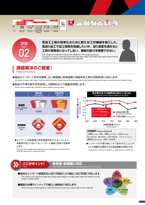
●独自のインサート形状を開発。広い断面積と拘束面積で高能率加工時の切削負荷に対応します。
課題解決のご提案! Developed a unique insert shape. Performs stable machining despite large cutting load generated during high-feed cutting with large cross-sectional and constraint areas.
Proposed solutions ●独自の不等分割方式を採用し、切削時のビビり振動を抑制します。
Adopts unique unequal pitch method to reduce chattering during cutting.
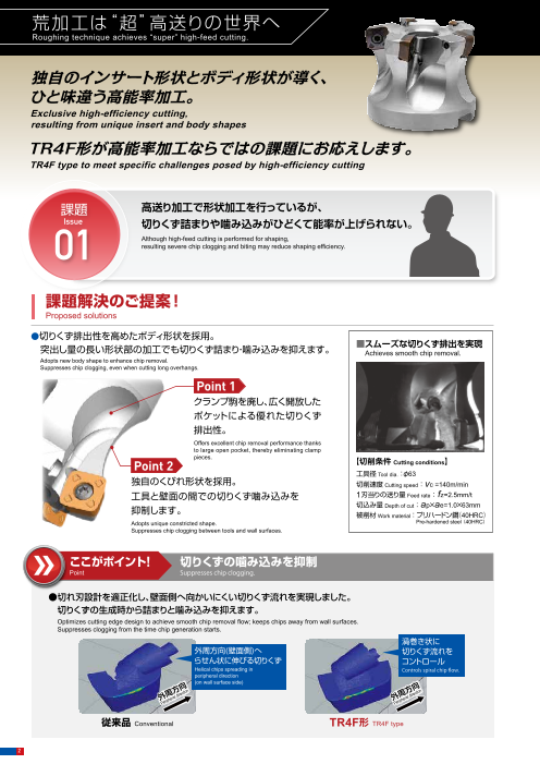
●切りくず排出性を高めたボディ形状を採用。
突出し量の長い形状部の加工でも切りくず詰まり・噛み込みを抑えます。 ■スムーズな切りくず排出を実現 従来品 TR4F形 各分割方法での限界切込深さ(L/D=6)Achieves smooth chip removal. Conventional TR4F type Comparison of the maximum depth of cut (L/D=6).
Adopts new body shape to enhance chip removal.
Suppresses chip clogging, even when cutting long overhangs. 1.4
1.2
Point 1 1断面積
クランプ駒を廃し、広く開放した Cross-sectional 0.8
area 0.6 ビビり振動を抑制して
ポケットによる優れた切りくず 100% 110% 0.4 約20%の能率向上 従来品(等分割)
Reduces chatter to improve Conventional (equal pitch)
排出性。 0.2 efficiency by roughly 20%. 不等分割品 Unequal pitch
Offers excellent chip removal performance thanks 0
to large open pocket, thereby eliminating clamp 600 650 700 750 800 850 900
pieces.
Point 2 【切削条件 Cutting conditions】 拘束面積 主軸回転数 [min-1]
工具径 Tool dia.:φ63 Constraint Spindle speed
独自のくびれ形状を採用。 切削速度 Cutting speed:vc =140m/min area 【切削条件 Cutting conditions】
工具と壁面の間での切りくず噛み込みを 1刃当りの送り量 Feed rate: fz=2.5mm/t 100% 135% 工具径 Tool dia.:φ50、刃数 No. of Flutes:4 枚刃 4 Flutes、
抑制します。 切込み量 Depth of cut:ap×ae=1.0×63mm fz=1.0mm/t、ae=35mm、OH=300mm、フルセット 被削材 Full setWork material:プリハードン鋼(40HRC)
Adopts unique constricted shape. Pre-hardened steel(40HRC) ●インサートの断面積と拘束面積を拡大することにより、 被削材Work material:S50C(220HB)
Suppresses chip clogging between tools and wall surfaces. 高負荷な加工においても、インサート強度と拘束力を確保 ●インサートを不等分割ピッチで配列することにより、
します。 ビビり振動の主要因である自励振動を抑制します。
! Secures insert strength and constraint force by enlarging cross-sectional and ここがポイント 切りくずの噛み込みを抑制 Unequal pitch reduces a vibration, a major factor of chattering.constraint areas even in high-load cutting.
Point Suppresses chip clogging.
●切れ刃設計を適正化し、壁面側へ向かいにくい切りくず流れを実現しました。
切りくずの生成時から詰まりと噛み込みを抑えます。 ここがポイント! 多用途・多鋼種に対応
Optimizes cutting edge design to achieve smooth chip removal flow; keeps chips away from wall surfaces. Point Meets the requirements of various applications and steel types.
Suppresses clogging from the time chip generation starts.
渦巻き状に
外周方向(壁面側)へ 切りくず流れを ●独自のインサート断面形状と切れ刃設計により幅広い加工形態に対応します。 面削
・The unique cross-sectional shape and cutting edge design of a single insert meets the needs of a wide Face millingらせん状に伸びる切りくず コントロール
Helical chips spreading in Controls spiral chip flow. range of cutting modes.
peripheral direction 溝 彫込み
(on wall surface side) Slotting Die-sinking
方向on 方向 ●豊富な材種ラインナップで幅広い被削材に対応します。
外周
cti ction
eral
dire 外周 direriph ripheral Pe Pe ・Diverse lineup of insert grades to meet the demands posed by a wide range of work materials.
傾斜 バーチカル
Ramping Vertical
従来品 Conventional TR4F形 TR4F type
2
軸方向切込み量 [mm]
Axial depth of cut
Page3
荒加工は“超”高送りの世界へ
Roughing technique achieves “super” high-feed cutting.
独自のインサート形状とボディ形状が導く、 JM4160 JP4105JS4060 JP4120 加工 荒
GX2140
ひと味違う高能率加工。 用途 Roughing銅 炭素鋼 ステンレス鋼 プリハードン鋼 焼入れ鋼 焼入れ鋼 Applications
合金鋼 工具鋼 焼入れ鋼 45~50HRC 50~60HRC
Exclusive high-efficiency cutting, 35~45HRCCopper Carbon steel Stainless steel Pre-hardened steel Hardened steel Hardened steelAlloy steel Tool steel Hardened steel 45̃50HRC 50̃60HRC
resulting from unique insert and body shapes 35̃45HRC
TR4F形が高能率加工ならではの課題にお応えします。
TR4F type to meet specific challenges posed by high-efficiency cutting 課題 荒加工工程の効率化のために新たな工作機械を導入した。
Issue 高送り加工で加工時間を短縮したいが、送り速度を速めると
工具が短寿命になってしまい、機械の能力を発揮できない。
課題 高送り加工で形状加工を行っているが、 02 New equipment installed to improve the efficiency of the roughing process.The goal is to reduce machining times with high-feed cutting. But higher feed rates reduce tool life
Issue 切りくず詰まりや噛み込みがひどくて能率が上げられない。 and keep the machine from delivering its full potential.
01 Although high-feed cutting is performed for shaping,resulting severe chip clogging and biting may reduce shaping efficiency. 課題解決のご提案!
Proposed solutions
●独自のインサート形状を開発。広い断面積と拘束面積で高能率加工時の切削負荷に対応します。
課題解決のご提案! Developed a unique insert shape. Performs stable machining despite large cutting load generated during high-feed cutting with large cross-sectional and constraint areas.
Proposed solutions ●独自の不等分割方式を採用し、切削時のビビり振動を抑制します。
Adopts unique unequal pitch method to reduce chattering during cutting.
●切りくず排出性を高めたボディ形状を採用。
突出し量の長い形状部の加工でも切りくず詰まり・噛み込みを抑えます。 ■スムーズな切りくず排出を実現 従来品 TR4F形 各分割方法での限界切込深さ(L/D=6)Achieves smooth chip removal. Conventional TR4F type Comparison of the maximum depth of cut (L/D=6).
Adopts new body shape to enhance chip removal.
Suppresses chip clogging, even when cutting long overhangs. 1.4
1.2
Point 1 1断面積
クランプ駒を廃し、広く開放した Cross-sectional 0.8
area 0.6 ビビり振動を抑制して
ポケットによる優れた切りくず 100% 110% 0.4 約20%の能率向上 従来品(等分割)
Reduces chatter to improve Conventional (equal pitch)
排出性。 0.2 efficiency by roughly 20%. 不等分割品 Unequal pitch
Offers excellent chip removal performance thanks 0
to large open pocket, thereby eliminating clamp 600 650 700 750 800 850 900
pieces.
Point 2 【切削条件 Cutting conditions】 拘束面積 主軸回転数 [min-1]
工具径 Tool dia.:φ63 Constraint Spindle speed
独自のくびれ形状を採用。 切削速度 Cutting speed:vc =140m/min area 【切削条件 Cutting conditions】
工具と壁面の間での切りくず噛み込みを 1刃当りの送り量 Feed rate: fz=2.5mm/t 100% 135% 工具径 Tool dia.:φ50、刃数 No. of Flutes:4 枚刃 4 Flutes、
抑制します。 切込み量 Depth of cut:ap×ae=1.0×63mm fz=1.0mm/t、ae=35mm、OH=300mm、フルセット 被削材 Full setWork material:プリハードン鋼(40HRC)
Adopts unique constricted shape. Pre-hardened steel(40HRC) ●インサートの断面積と拘束面積を拡大することにより、 被削材Work material:S50C(220HB)
Suppresses chip clogging between tools and wall surfaces. 高負荷な加工においても、インサート強度と拘束力を確保 ●インサートを不等分割ピッチで配列することにより、
します。 ビビり振動の主要因である自励振動を抑制します。
! Secures insert strength and constraint force by enlarging cross-sectional and ここがポイント 切りくずの噛み込みを抑制 Unequal pitch reduces a vibration, a major factor of chattering.constraint areas even in high-load cutting.
Point Suppresses chip clogging.
●切れ刃設計を適正化し、壁面側へ向かいにくい切りくず流れを実現しました。
切りくずの生成時から詰まりと噛み込みを抑えます。 ここがポイント! 多用途・多鋼種に対応
Optimizes cutting edge design to achieve smooth chip removal flow; keeps chips away from wall surfaces. Point Meets the requirements of various applications and steel types.
Suppresses clogging from the time chip generation starts.
渦巻き状に
外周方向(壁面側)へ 切りくず流れを ●独自のインサート断面形状と切れ刃設計により幅広い加工形態に対応します。 面削
・The unique cross-sectional shape and cutting edge design of a single insert meets the needs of a wide Face millingらせん状に伸びる切りくず コントロール
Helical chips spreading in Controls spiral chip flow. range of cutting modes.
peripheral direction 溝 彫込み
(on wall surface side) Slotting Die-sinking
方向on 方向 ●豊富な材種ラインナップで幅広い被削材に対応します。
外周
cti ction
eral
dire 外周 direriph ripheral Pe Pe ・Diverse lineup of insert grades to meet the demands posed by a wide range of work materials.
傾斜 バーチカル
Ramping Vertical
従来品 Conventional TR4F形 TR4F type
3
軸方向切込み量 [mm]
Axial depth of cut
Page4
ラインナップ
Line Up
シャンクタイプ は数字、 は英文字が入ります。 Shank type TR4F40 32- Numeric figure in a circle and Alphabetical character comes in a square .
Fig.1( 一般形)
(Standard type)
L1 ls
L
Fig.2( アンダーカット形)
(Undercut type)
L1 ls (クーラント穴有)
L With Coolant hole
寸 法 Size (mm)
タイプ 商品コード 在庫 刃数 形状 適用インサート 希望小売価格(円)
Type Item Code Stock No.of Flutes φDc2 L L1 ℓs φDs Shape Recommended Insert SuggestedRetail Price( ¥)
レ
ギ TR4F4032S32-2 ★ 2 32 150 70 80 32 Fig.1 41,300
ュ
ラ
ー TR4F4040S32-3 ★ 3 40 150 50 100 32 Fig.2 SDNW120520TR 47,800
SDNW120520TR-P
ロ TR4F4032L32-2 ★ 2 32 200 120 80 32 Fig.1 SDMT120520TR 43,500
ン
グ TR4F4040L32-3 ★ 3 40 250 50 200 32 Fig.2 56,000
モジュラータイプ は数字が入ります。 Modular type TR4F40 M- Numeric figure comes in a circle .
Lf
C E(切
M 欠部幅)
L1 (クーラント穴有)
L2 With Coolant hole
商品コード 在庫 刃数 寸 法 Size (mm) 適用インサート 希望小売価格(円)
Item Code Stock No.of Flutes φDc2 Lf L1 L2 φD2 φDb M C E Recommended Insert SuggestedRetail Price( ¥)
TR4F4032M-2 ★ 2 32 40 6 23 17 28.8 M16 12 22 SDNW120520TR 39,270
SDNW120520TR-P
※ TR4F4040M-3 ★ 3 40 40 6 23 17 28.8 M16 12 22 SDMT120520TR 44,880
※と超硬シャンク (p5) をセットで使用すると干渉がありません。 When ※ and carbide shanks for Modular Mill (page 5) are used together as a set, there is no interference.
【注意】 モジュラーミル及び専用シャンク、専用アーバの「工具端面」「モジュラーネジ部」にグリースなどの潤滑剤は塗布しないでください。
【Note】 Do not apply lubricants such as grease,etc. to the "contact faces" and "modular screws" of the "modular mill","special shanks" and "special arbor".
部品番号 Parts
本体には付属しておりません(別売) Not included with product (sold separately)
部品名 クランプねじ
Parts Clamp screw レンチ ねじ焼き付き防止剤 アーバ用ねじ
Wrench Screw anti-seizure agent Arbor screw
形状 a
Shape
d
f c
締付 希望小売価格 希望小売価格 希望小売価格 希望小売価格
トルク (円) (円) (円) (円)
適用カッタ Fastening torque Suggested retail Suggested retail Suggested retail a φb c d f Suggested retail
Cutter body (N・m) price (¥) price (¥) price (¥) price (¥)
TR4F40○○ S/L/M (32)-○
TR4F4050 B□-○ 100-178 M10×1.5 16 35 25 8 1,460
TR4F4063 B□-○ 100-179 M12×1.75 18 42 30 10 1,460
TR4F4080 BM-○ 262-141 2.9 720 105-T15 1,760 P-37 840
TR4F4080 B-○ 100-180 M16×2.0 24 51 35 14 1,460
TR4F4100 B□-○
【注意】クランプねじは消耗品です。使用環境により交換寿命は変化しますので早めの交換をお願い致します。クランプねじは予備がシャンクタイプとモジュラータイプは1本、ボ
アタイプは 2本付属します。
環境負荷低減への配慮により、ドライバー、ねじ焼き付き防止剤は別売りとさせていただきました。ご理解・ご協力をお願いいたします。
【Note】 The clamp screw is a consumable part. Since replacement life depends on the use environment, it is recommended that it be replaced at an early stage.
Includes one spare clamp screw for shank type and modular, two spare clamp screws for bore type.
In consideration of reducing environmental loads, the screwdriver and screw anti-seizure agent are now sold separately to avoid sending unnecessary
duplicate tools. We hope you will understand our reasoning.
★印:新商品の標準在庫品です。★:Stocked items of new products. ●印:標準在庫品です。●:Stocked items.
4
Long Regular
φDc2 φDc2 φDc2
φD2
φDb
φb
φDs φDs
Page5
ボアタイプ TR4F4 B - は数字、 は英文字が入ります。Bore type Numeric figure in a circle and Alphabetical character comes in a square .
φDb
φd
a
φd1
φDc2 (クーラント穴有)
With Coolant hole
タイプ 商品コード 刃数 寸 法 Size (mm)在庫 適用インサート 希望小売価格(円)
Type Item Code Stock No.of Flutes φDc2 φDb Lf l a b φd φd1 Recommended Insert SuggestedRetail Price( ¥)
TR4F4050B-3 ● 3 48,860
TR4F4050B-4 ● 4 50 47 50 19 8.4 5 22.225 17 59,470
内 TR4F4050B-5 ★ 5 68,380
径
イ TR4F4063B-4 ● 4 61,820
ン TR4F4063B-5 ● 5 63 60 50 19 8.4 5 22.225 17 67,830
チ TR4F4063B-6 ★ 6 78,810
サ
イ TR4F4080B-5 ● 5 83,130
ズ 80 76 70 32 12.7 8 31.75 26TR4F4080B-7 ★ 7 96,700
TR4F4100B-6 ● 6 109,140
100 96 70 32 12.7 8 31.75 26
TR4F4100B-8 ★ 8 SDNW120520TR 126,510
SDNW120520TR-P
TR4F4050BM-3 ● 3 SDMT120520TR 48,860
TR4F4050BM-4 ● 4 50 47 50 20 10.4 6.3 22 17 59,470
内 TR4F4050BM-5 ★ 5 68,380
径 TR4F4063BM-4 ● 4 61,820
ミ TR4F4063BM-5 ● 5 63 60 50 20 10.4 6.3 22 17 67,830リ
サ TR4F4063BM-6 ★ 6 78,810
イ TR4F4080BM-5 ● 5 83,130
ズ 80 76 70 22 12.4 7 27 20TR4F4080BM-7 ★ 7 96,700
TR4F4100BM-6 ● 6 109,140
100 96 70 25.5 14.4 8 32 26
TR4F4100BM-8 ★ 8 126,510
部品番号 【注意】アーバ用ねじは付属しません。Parts 【Note】Arbor screw is not included.
本体には付属しておりません(別売) Not included with product (sold separately)
部品名 クランプねじ
Parts Clamp screw レンチ ねじ焼き付き防止剤 アーバ用ねじ モジュラーミル専用シャンク The Shanks for Modular Mill
Wrench Screw anti-seizure agent Arbor screw
形状 ■ 超硬シャンク L3LL1
Shape L f L2 RsCarbide shank
M
商品コード 寸 法 Size (mm)在庫 適用カッタ エアー穴有無 希望小売価格(円)
締付 希望小売価格 希望小売価格 希望小売価格 希望小売価格 Item Code Stock 2 3
トルク (円) (円) (円) (円) φD M L L Lf L L
With/ Suggested
2 1 ℓs φD3 φDs Cutter body without air hole Retail Price( ¥)
適用カッタ Fastening torque Suggested retail Suggested retail Suggested retail a φb c d f Suggested retail ASC32-17-160-80 ● 200 160 80 120 80 85,680
Cutter body (N・m) price (¥) price (¥) price (¥) price (¥) ASC32-17-210-110 ● 250 210 110 150 100 86,700
TR4F40○○ S/L/M (32)-○ ASC32-17-260-140 ● 17 M16 300 260 40 140 180 120 28 32 φ32 ○ 103,020
TR4F4050 B□-○ 100-178 M10×1.5 16 35 25 8 1,460 φ40ASC32-17-310-190 ● 350 310 190 230 120 139,740
TR4F4063 B□-○ 100-179 M12×1.75 18 42 30 10 1,460
262-141 2.9 720 105-T15 1,760 P-37 840 ASC32-17-360-240 ● 400 360 240 280 120 176,460TR4F4080 BM-○ ASC32-17-260-80 ● 300 260 180 103,020
TR4F4080 B-○ 100-180 M16×2.0 24 51 35 14 1,460 ASC32-17-310-80 ● 17 M16 350 310 40 80 120 230 28 32 φ32 ○ 139,740
TR4F4100 B□-○ φ40ASC32-17-360-80 ● 400 360 280 176,460
【注意】 ①上記以外にもモジュラーミル専用シャンクを多数ラインナップしております。詳細については総合カタログまたはホームページで確認をお願いします。
②市販のミーリングチャック、焼ばめホルダーにて使用できます。
【Note】 ① Various other shanks for Modular Mill are also available. For more information, please refer to our general catalog or visit our website(. http://www.moldino.com)
② Commercial milling chucks or shrink-fit holders can be used.
5
Internal diameter mm size Internal diameter inch size
φD 2
φD 3
b
φDs
l
Lf
Page6
ラインナップ
Line Up
インサート Insert
Fig.1 T Fig.2 T
T
Fig.3
SDNW120520TR SDNW120520TR-P SDMT120520TR
P 鋼 Carbon steel
:一般切削・第一推奨
M SUS等 SUS, etc. General cutting, First recommendation
K FC・FCD :一般切削・第二推奨
General cutting, Second recommendation
H 高硬度材 Hardened steels
商品コード 精度 AJコート JSコート GXコート 希望小売価(円)
Tolerance AJ-Coated JS-Coated GX-Coated
寸 法Size (mm) 形 状
Item Code Suggested Retail Price Class Shape JP4105 JP4120 JM4160 JS4060 GX2140 φW T (¥)
SDNW120520TR ● ● ● ● ● Fig.1 1,360
N 級 N 5.56
SDNW120520TR-P ● 12.7 Fig.2 1,360
SDMT120520TR M 級 M ★※1 ★ ★ ★ 5.76 Fig.3 1,360
※ 1:析出硬化系ステンレス鋼の加工にもご使用頂けます。 ※ 1:Can be used to process the precipitation hardend stainless steel. 析出硬化系 =precipitation hardend
【注意】GXコート、JSコートは通電式タッチセンサーに反応しませんのでご注意ください。
【Note】Please note that the GX coating and JS coating do not cause a reaction in conductive touch sensors.
材種マップ(35HRC未満の鋼材) 被削材別推奨材種マップ
Grade map for less than 35HRC Grade map for work material
◀耐チッピング性 耐摩耗性▶ 被削材硬度 Work Hardness 被削材硬度 Work Hardness 被削材硬度 Work Hardness
Chipping resistance Wear resistance 低い Low High 高い 低い Low High 高い 低い Low High 高い
不
GX2140 安 JS4060定
加 JS4060
工 JM4160 GX2140
JS4060
JP4120
◀湿式加工 乾式加工▶ GX2140
Wet cutting Dry cutting JP4105 JP4120 JP4120
安
定
GX2140 加工
一般構造用鋼 炭素鋼・合金鋼 炭素鋼・合金鋼 焼入れ鋼 焼入れ鋼 ステンレス鋼系材料 鋳鉄
JS4060 (200HB以下)(30HRC以下)(30~45HRC)(45~50HRC)(50~60HRC) SUS FC,FCDMild Steels Carbon steel, Alloy steel Carbon steel Hardened Steels Hardened Steels Stainless Steel materials Cast iron
(200HB or less) (30HRC or less) Alloy steel Pre-Harden Steels
インサートの使い分け Proper use of insets
SDNW120520TR SDNW120520TR-P SDMT120520TR
刃先強度に優れた第一推奨インサート 突き出し量が短く、断続の少ない加工に推奨 ブレーカ付きインサート
一般的な高送り加工に適します 特にプリハードン鋼(P20、P21材)に適します 低剛性なワークや低馬力なM/C での荒加工に適します
The recommended default insert offers superior cutting Recommended for relatively continuous (uninterrupted) Breaker type insert.
edge strength. Ideal for general high-feed cutting. cutting with short overhangs. Ideal for rough machining with low-rigidity work materials and
Ideal for pre-hardened steel (P20 and P21 materials). low-horsepower M/C.
★印:新商品の標準在庫品です。★:Stocked items of new products. ●印:標準在庫品です。●:Stocked items.
6
φW
Stable Unstable
machining machining
φW
φW
Page7
標準切削条件表
Recommended Cut t ing Condi t ions
ae ap
①シャンクタイプ・モジュラータイプ Shank type / Modular type
等高線荒加工標準切削条件 Standard cutting conditions for contour roughing
タイプ Type シャンクタイプ Shank Type モジュラータイプ Modular Type
外径 Dc Φ32(2枚刃) (2 Flutes) Φ40(3枚刃) (3 Flutes) Φ32(2枚刃) (2 Flutes) Φ40(3枚刃) (3 Flutes)
推奨 Tool dia Dc
被削材 材種 <3Dc <3Dc <3Dc <3Dc
Work Material Recommended 突出し比率
inserts grade Overhang 3Dc-5Dc 5Dc-7Dc >7Dc 3Dc-5Dc 5Dc-7Dc >7Dc
ratio 汎用 高速加工 汎用 高速加工 汎用 高速加工 汎用 高速加工
General purpose High-speed Cutting General purpose High-speed Cutting General purpose High-speed Cutting General purpose High-speed Cutting
n (min-1) 1490 1990 1190 1590 1490 1990 1490 1290 1090 1190 1590 1190 1030 880
一般構造用鋼 Vc(m/min) 150 200 150 200 150 200 150 130 110 150 200 150 130 110
Mild Steels GX2140 V f (mm/min) 5360 7960 6430 9540 5360 7960 5360 4640 3920 6430 9540 6430 5560 4750
(200HB fz(mm/t) 1.8 2.0 1.8 2.0 1.8 2.0 1.8 1.8 1.8 1.8 2.0 1.8 1.8 1.8
以下) JS4060 ap(mm) 1.0 1.0 1.0 1.0 1.0 1.0 1.0 0.8 0.8 1.0 1.0 1.0 0.8 0.8
(200HB or less) ae(mm) 26 26 32 32 26 26 26 26 26 32 32 32 32 32
Q(cm3/min) 139 207 206 305 139 207 139 97 82 206 305 206 142 122
炭素鋼 n (min-1) 1490 1990 1190 1590 1490 1990 1490 1290 1090 1190 1590 1190 1030 880
合金鋼 Vc(m/min) 150 200 150 200 150 200 150 130 110 150 200 150 130 110
Carbon Steels GX2140 V f (mm/min) 5360 7960 6430 9540 5360 7960 5360 4640 3920 6430 9540 6430 5560 4750
Alloy Steels fz(mm/t) 1.8 2.0 1.8 2.0 1.8 2.0 1.8 1.8 1.8 1.8 2.0 1.8 1.8 1.8
(35HRC JS4060 ap(mm) 1.0 1.0 1.0 1.0 1.0 1.0 1.0 0.8 0.8 1.0 1.0 1.0 0.8 0.8
以下) ae(mm) 26 26 32 32 26 26 26 26 26 32 32 32 32 32
(35HRC or less) Q(cm3/min) 139 207 206 305 139 207 139 97 82 206 305 206 142 122
炭素鋼 n (min
-1) 1290 1490 1030 1190 1290 1490 1290 1090 900 1030 1190 1030 880 720
Vc(m/min) 130 150 130 150 130 150 130 110 90 130 150 130 110 90
合金鋼
JP4120 Vf(mm/min) 4640 5960 5560 7140 4640 5960 4640 3490 2880 5560 7140 5560 4220 3460Carbon Steels
Alloy Steels fz(mm/t) 1.8 2.0 1.8 2.0 1.8 2.0 1.8 1.6 1.6 1.8 2.0 1.8 1.6 1.6JS4060
(35 〜 ap(mm) 1.0 1.0 1.0 1.0 1.0 1.0 1.0 0.8 0.8 1.0 1.0 1.0 0.8 0.8
45HRC) ae(mm) 26 26 32 32 26 26 26 26 26 32 32 32 32 32Q(cm3/min) 121 155 178 228 121 155 121 73 60 178 228 178 108 89
n (min-1) 990 1990 800 1590 990 1990 990 850 700 800 1590 800 680 560
Vc(m/min) 100 200 100 200 100 200 100 85 70 100 200 100 85 70
ステンレス鋼 V f (mm/min) 1980 3980 2400 4770 1980 3980 1980 1700 1400 2400 4770 2400 2040 1680
Stainless Steels JM4160 fz(mm/t) 1.0 1.0 1.0 1.0 1.0 1.0 1.0 1.0 1.0 1.0 1.0 1.0 1.0 1.0
SUS ap(mm) 1.0 1.0 1.0 1.0 1.0 1.0 1.0 0.8 0.8 1.0 1.0 1.0 0.8 0.8
ae(mm) 26 26 32 32 26 26 26 26 26 32 32 32 32 32
Q(cm3/min) 51 103 77 153 51 103 51 35 29 77 153 77 52 43
n (min-1) 1490 1990 1190 1590 1490 1990 1490 1290 1090 1190 1590 1190 1030 880
鋳鉄 Vc(m/min) 150 200 150 200 150 200 150 130 110 150 200 150 130 110GX2140
Cast Iron V f (mm/min) 5960 7960 7140 9540 5960 7960 5960 5160 4360 7140 9540 7140 6180 5280
FC JS4060 fz(mm/t) 2.0 2.0 2.0 2.0 2.0 2.0 2.0 2.0 2.0 2.0 2.0 2.0 2.0 2.0
JP4120 ap(mm) 1.0 1.0 1.0 1.0 1.0 1.0 1.0 0.8 0.8 1.0 1.0 1.0 0.8 0.8FCD ae(mm) 26 26 32 32 26 26 26 26 26 32 32 32 32 32
Q(cm3/min) 155 207 228 305 155 207 155 107 91 228 305 228 158 135
n (min-1) 800 900 640 720 800 900 800 700 600 640 720 640 560 480
焼入れ鋼 Vc(m/min) 80 90 80 90 80 90 80 70 60 80 90 80 70 60
Hardened Steels JP4120 V f (mm/min) 800 1440 960 1730 800 1440 800 700 600 960 1730 960 840 720
(45〜 fz(mm/t) 0.5 0.8 0.5 0.8 0.5 0.8 0.5 0.5 0.5 0.5 0.8 0.5 0.5 0.5JP4105 ap(mm) 0.8 0.8 0.8 0.8 0.8 0.8 0.8 0.6 0.6 0.8 0.8 0.8 0.6 0.6
50HRC) ae(mm) 26 26 32 32 26 26 26 26 26 32 32 32 32 32
Q(cm3/min) 17 30 25 44 17 30 17 11 9 25 44 25 16 14
n (min-1) 800 900 640 720 800 900 800 700 600 640 720 640 560 480
焼入れ鋼 Vc(m/min) 80 90 80 90 80 90 80 70 60 80 90 80 70 60
JP4105 V f (mm/min) 640 1080 770 1300 640 1080 640 560 480 770 1300 770 670 580Hardened Steels
(50〜 fz(mm/t) 0.4 0.6 0.4 0.6 0.4 0.6 0.4 0.4 0.4 0.4 0.6 0.4 0.4 0.4JP4120 ap(mm) 0.8 0.8 0.8 0.8 0.8 0.8 0.8 0.6 0.6 0.8 0.8 0.8 0.6 0.6
60HRC) ae(mm) 26 26 32 32 26 26 26 26 26 32 32 32 32 32
Q(cm3/min) 13 22 20 33 13 22 13 9 7 20 33 20 13 11
バーチカル荒加工標準切削条件 Standard cutting conditions for vertical roughing
推奨 外径 Dc Φ32(2枚刃) (2 Flutes) φ40(3枚刃) (3 Flutes)
被削材 材種 Tool dia Dc
Work Material Recommended 突出し比率
inserts grade <3Dc 3Dc-5Dc 5Dc-7Dc >7Dc <3Dc 3Dc-5Dc 5Dc-7Dc >7DcOverhang ratio
n (min-1) 1990 1990 1690 1490 1590 1590 1350 1190
鋳鉄 JP4120 Vc(m/min) 200 200 170 150 200 200 170 150
Cast Iron
GX2140 V f (mm/min) 600 600 340 300 720 720 410 360FC fz(mm/t) 0.15 0.15 0.1 0.1 0.15 0.15 0.1 0.1
FCD JS4060 pf(mm) ≦ 0.5Dc ≦ 0.5Dc
ae(mm) ≦ 9.0 ≦ 9.0
【注意】①本表は切削条件の目安を示すものです。機械剛性やツーリング、加工物の状態に合わせて調整してください。 pf
特に、溝切削を伴う、またはそれに近い切込み幅の加工などで、切りくずの噛み込みやビビり振動が発生し、トラブルに至る場合がありますので下記を参考に調整してください。
・回転数、テーブル送り量を 50~ 70%下げる。
・切込み深さapを 50~ 70%下げる。 ae
・切込み幅 aeを 50~ 70%下げる。
② GXコート、JSコートは通電式タッチセンサーに反応しませんのでご注意ください。
③「JP4105」は高硬度鋼専用材種で、生材には適しません。
④強断続切削、突出しが長い場合及び湿式切削には「JM4160」をご推奨します。
⑤切りくず噛み込みによる工具損傷防止のため、必ずエアーブロー等による切りくず除去を行ってください。
⑥排出した切りくずは、飛散し作業者を切傷させ、火傷あるいは目に入って負傷させる恐れがありますので、ご使用に際してはその周囲に安全カバーを取付け、保護メガネ等の保
護具を着用し、安全な環境で作業されることをお願い致します。
⑦インサートの交換は早めに行い、過度の使用による破損を防止してください。
⑧下記に単位時間当たりの切りくず排出量Qを示します。
Q(cm3/min)=ap(mm)×ae(mm)×Vf(mm/min)/1000 7
Page8
標準切削条件表
Recommended Cut t ing Condi t ions
②ボアタイプ Bore type
等高線荒加工標準切削条件 Standard cutting conditions for contour roughing
外径 Dc Φ 50(3枚刃) (3 Flutes) φ50(4枚刃) (4 Flutes) φ50(5枚刃) (5 Flutes) φ63(4枚刃) (4 Flutes) φ63(5枚刃) (5 Flutes) φ63(6枚刃) (6 Flutes)
推奨 Tool dia Dc
被削材 材種 突出し比率 <3Dc <3Dc <3Dc <3Dc <3Dc <3Dc 被削材Work Material Recommended Work Material
inserts grade Overhang 3Dc-5Dc 5Dc-7Dc >7Dc 3Dc-5Dc 5Dc-7Dc >7Dc 3Dc-5Dc 5Dc-7Dc >7Dc 3Dc-5Dc 5Dc-7Dc >7Dc 3Dc-5Dc 5Dc-7Dc >7Dc 3Dc-5Dc 5Dc-7Dc >7Dc
ratio 汎用 高速加工 汎用 高速加工 汎用 高速加工 汎用 高速加工 汎用 高速加工 汎用 高速加工
General purpose High-speed Cutting General purpose High-speed Cutting General purpose High-speed Cutting General purpose High-speed Cutting General purpose High-speed Cutting General purpose High-speed Cutting
n (min-1) 950 1270 950 830 700 950 1270 950 830 700 950 1270 950 830 700 760 1010 760 660 560 760 1010 760 660 560 760 1010 760 660 560
一般構造用鋼 Vc(m/min) 150 200 150 130 110 150 200 150 130 110 150 200 150 130 110 150 200 150 130 110 150 200 150 130 110 150 200 150 130 110 一般構造用鋼
Mild Steels GX2140 V f (mm/min) 5130 7620 5130 4480 3780 6840 10160 6840 5980 5040 8550 12700 8550 7470 6300 5470 8080 5470 4750 4030 6840 10100 6840 5940 5040 8210 12120 8210 7130 6050 Mild Steels
(200HB fz(mm/t) 1.8 2.0 1.8 1.8 1.8 1.8 2.0 1.8 1.8 1.8 1.8 2.0 1.8 1.8 1.8 1.8 2.0 1.8 1.8 1.8 1.8 2.0 1.8 1.8 1.8 1.8 2.0 1.8 1.8 1.8JS4060 (200HB以下) ap(mm) 1.0 1.0 1.0 0.8 0.8 1.0 1.0 1.0 0.8 0.8 1.0 1.0 1.0 0.8 0.8 1.0 1.0 1.0 0.8 0.8 1.0 1.0 1.0 0.8 0.8 1.0 1.0 1.0 0.8 0.8 以下)
(200HB or less) ae(mm) 40 40 40 40 40 40 40 40 40 40 40 40 40 40 40 50 50 50 50 50 50 50 50 50 50 50 50 50 50 50 (200HB or less)
Q(cm3/min) 205 305 205 143 121 274 406 274 191 161 342 508 342 239 202 274 404 274 190 161 342 505 342 238 202 411 606 411 285 242
炭素鋼 n (min-1) 950 1270 950 830 700 950 1270 950 830 700 950 1270 950 830 700 760 1010 760 660 560 760 1010 760 660 560 760 1010 760 660 560 炭素鋼
合金鋼 Vc(m/min) 150 200 150 130 110 150 200 150 130 110 150 200 150 130 110 150 200 150 130 110 150 200 150 130 110 150 200 150 130 110 合金鋼
Carbon Steels GX2140 V f (mm/min) 5130 7620 5130 4480 3780 6840 10160 6840 5980 5040 8550 12700 8550 7470 6300 5470 8080 5470 4750 4030 6840 10100 6840 5940 5040 8210 12120 8210 7130 6050 Carbon Steels
Alloy Steels fz(mm/t) 1.8 2.0 1.8 1.8 1.8 1.8 2.0 1.8 1.8 1.8 1.8 2.0 1.8 1.8 1.8 1.8 2.0 1.8 1.8 1.8 1.8 2.0 1.8 1.8 1.8 1.8 2.0 1.8 1.8 1.8 Alloy Steels
(35HRC JS4060 ap(mm) 1.0 1.0 1.0 0.8 0.8 1.0 1.0 1.0 0.8 0.8 1.0 1.0 1.0 0.8 0.8 1.0 1.0 1.0 0.8 0.8 1.0 1.0 1.0 0.8 0.8 1.0 1.0 1.0 0.8 0.8 (35HRC
以下) ae(mm) 40 40 40 40 40 40 40 40 40 40 40 40 40 40 40 50 50 50 50 50 50 50 50 50 50 50 50 50 50 50 以下)
(35HRC or less) Q(cm3/min) 205 305 205 143 121 274 406 274 191 161 342 508 342 239 202 274 404 274 190 161 342 505 342 238 202 411 606 411 285 242 (35HRC or less)
炭素鋼 n (min
-1) 830 950 830 700 570 830 950 830 700 570 830 950 830 700 570 660 760 660 560 450 660 760 660 560 450 660 760 660 560 450
Vc(m/min) 130 150 130 110 90 130 150 130 110 90 130 150 130 110 90 130 150 130 110 90 130 150 130 110 90 130 150 130 110 90 炭素鋼
合金鋼
JP4120 Vf(mm/min) 4480 5700 4480 3360 2740 5980 7600 5980 4480 3650 7470 9500 7470 5600 4560 4750 6080 4750 3580 2880 5940 7600 5940 4480 3600 7130 9120 7130 5380 4320
合金鋼
Carbon Steels Carbon Steels
Alloy Steels fz(mm/t) 1.8 2.0 1.8 1.6 1.6 1.8 2.0 1.8 1.6 1.6 1.8 2.0 1.8 1.6 1.6 1.8 2.0 1.8 1.6 1.6 1.8 2.0 1.8 1.6 1.6 1.8 2.0 1.8 1.6 1.6JS4060 Alloy Steels
(35 〜 ap(mm) 1.0 1.0 1.0 0.8 0.8 1.0 1.0 1.0 0.8 0.8 1.0 1.0 1.0 0.8 0.8 1.0 1.0 1.0 0.8 0.8 1.0 1.0 1.0 0.8 0.8 1.0 1.0 1.0 0.8 0.8ae(mm) (35 〜45HRC) 40 40 40 40 40 40 40 40 40 40 40 40 40 40 40 50 50 50 50 50 50 50 50 50 50 50 50 50 50 50Q(cm3/min) 179 228 179 108 88 239 304 239 143 117 299 380 299 179 146 238 304 238 143 115 297 380 297 179 144 357 456 357 215 173 45HRC)
n (min-1) 640 1270 640 540 450 640 1270 640 540 450 640 1270 640 540 450 510 1010 510 430 350 510 1010 510 430 350 510 1010 510 430 350
Vc(m/min) 100 200 100 85 70 100 200 100 85 70 100 200 100 85 70 100 200 100 85 70 100 200 100 85 70 100 200 100 85 70
ステンレス鋼 V f (mm/min) 1920 3810 1920 1620 1350 2560 5080 2560 2160 1800 3200 6350 3200 2700 2250 2040 4040 2040 1720 1400 2550 5050 2550 2150 1750 3060 6060 3060 2580 2100 ステンレス鋼
Stainless Steels JM4160 fz(mm/t) 1.0 1.0 1.0 1.0 1.0 1.0 1.0 1.0 1.0 1.0 1.0 1.0 1.0 1.0 1.0 1.0 1.0 1.0 1.0 1.0 1.0 1.0 1.0 1.0 1.0 1.0 1.0 1.0 1.0 1.0 Stainless Steels
SUS ap(mm) 1.0 1.0 1.0 0.8 0.8 1.0 1.0 1.0 0.8 0.8 1.0 1.0 1.0 0.8 0.8 1.0 1.0 1.0 0.8 0.8 1.0 1.0 1.0 0.8 0.8 1.0 1.0 1.0 0.8 0.8 SUS
ae(mm) 40 40 40 40 40 40 40 40 40 40 40 40 40 40 40 50 50 50 50 50 50 50 50 50 50 50 50 50 50 50
Q(cm3/min) 77 152 77 52 43 102 203 102 69 58 128 254 128 86 72 102 202 102 69 56 128 253 128 86 70 153 303 153 103 84
n (min-1) 950 1270 950 830 700 950 1270 950 830 700 950 1270 950 830 700 760 1010 760 660 560 760 1010 760 660 560 760 1010 760 660 560
鋳鉄 Vc(m/min) 150 200 150 130 110 150 200 150 130 110 150 200 150 130 110 150 200 150 130 110 150 200 150 130 110 150 200 150 130 110GX2140
Cast Iron V f (mm/min)
鋳鉄
5700 7620 5700 4980 4200 7600 10160 7600 6640 5600 9500 12700 9500 8300 7000 6080 8080 6080 5280 4480 7600 10100 7600 6600 5600 9120 12120 9120 7920 6720 Cast Iron
FC JS4060 fz(mm/t) 2.0 2.0 2.0 2.0 2.0 2.0 2.0 2.0 2.0 2.0 2.0 2.0 2.0 2.0 2.0 2.0 2.0 2.0 2.0 2.0 2.0 2.0 2.0 2.0 2.0 2.0 2.0 2.0 2.0 2.0
JP4120 ap(mm) 1.0 1.0 1.0 0.8 0.8 1.0 1.0 1.0 0.8 0.8 1.0 1.0 1.0 0.8 0.8 1.0 1.0 1.0 0.8 0.8 1.0 1.0 1.0 0.8 0.8 1.0 1.0 1.0 0.8 0.8 FCFCD ae(mm) 40 40 40 40 40 40 40 40 40 40 40 40 40 40 40 50 50 50 50 50 50 50 50 50 50 50 50 50 50 50 FCD
Q(cm3/min) 228 305 228 159 134 304 406 304 212 179 380 508 380 266 224 304 404 304 211 179 380 505 380 264 224 456 606 456 317 269
n (min-1) 510 570 510 450 380 510 570 510 450 380 510 570 510 450 380 400 450 400 350 300 400 450 400 350 300 400 450 400 350 300
焼入れ鋼 Vc(m/min) 80 90 80 70 60 80 90 80 70 60 80 90 80 70 60 80 90 80 70 60 80 90 80 70 60 80 90 80 70 60
JP4120 V f (mm/min)
焼入れ鋼
770 1370 770 680 570 1020 1820 1020 900 760 1280 2280 1280 1130 950 800 1440 800 700 600 1000 1800 1000 880 750 1200 2160 1200 1050 900
Hardened Steels Hardened Steels
(45〜 fz(mm/t) 0.5 0.8 0.5 0.5 0.5 0.5 0.8 0.5 0.5 0.5 0.5 0.8 0.5 0.5 0.5 0.5 0.8 0.5 0.5 0.5 0.5 0.8 0.5 0.5 0.5 0.5 0.8 0.5 0.5 0.5JP4105 ap(mm) 0.8 0.8 0.8 0.6 0.6 0.8 0.8 0.8 0.6 0.6 0.8 0.8 0.8 0.6 0.6 0.8 0.8 0.8 0.6 0.6 0.8 0.8 0.8 0.6 0.6 0.8 0.8 0.8 0.6 0.6 (45〜
50HRC) ae(mm) 40 40 40 40 40 40 40 40 40 40 40 40 40 40 40 50 50 50 50 50 50 50 50 50 50 50 50 50 50 50 50HRC)
Q(cm3/min) 25 44 25 16 14 33 58 33 22 18 41 73 41 27 23 32 58 32 21 18 40 72 40 26 23 48 86 48 32 27
n (min-1) 510 570 510 450 380 510 570 510 450 380 510 570 510 450 380 400 450 400 350 300 400 450 400 350 300 400 450 400 350 300
焼入れ鋼 Vc(m/min) 80 90 80 70 60 80 90 80 70 60 80 90 80 70 60 80 90 80 70 60 80 90 80 70 60 80 90 80 70 60
JP4105 V f (mm/min)
焼入れ鋼
610 1030 610 540 460 820 1370 820 720 610 1020 1710 1020 900 760 640 1080 640 560 480 800 1350 800 700 600 960 1620 960 840 720
Hardened Steels Hardened Steels
(50〜 fz(mm/t) 0.4 0.6 0.4 0.4 0.4 0.4 0.6 0.4 0.4 0.4 0.4 0.6 0.4 0.4 0.4 0.4 0.6 0.4 0.4 0.4 0.4 0.6 0.4 0.4 0.4 0.4 0.6 0.4 0.4 0.4JP4120 ap(mm) 0.8 0.8 0.8 0.6 0.6 0.8 0.8 0.8 0.6 0.6 0.8 0.8 0.8 0.6 0.6 0.8 0.8 0.8 0.6 0.6 0.8 0.8 0.8 0.6 0.6 0.8 0.8 0.8 0.6 0.6 (50〜
60HRC) ae(mm) 40 40 40 40 40 40 40 40 40 40 40 40 40 40 40 50 50 50 50 50 50 50 50 50 50 50 50 50 50 50 60HRC)
Q(cm3/min) 20 33 20 13 11 26 44 26 17 15 33 55 33 22 18 26 43 26 17 14 32 54 32 21 18 38 65 38 25 22
バーチカル荒加工標準切削条件 Standard cutting conditions for vertical roughing
推奨 外径 Dc Φ 50(3枚刃) (3 Flutes) φ50(4枚刃) (4 Flutes) φ50(5枚刃) (5 Flutes) φ63(4枚刃) (4 Flutes) φ63(5枚刃) (5 Flutes) φ63(6枚刃) (6 Flutes)
被削材 材種 Tool dia Dc 被削材
Work Material Recommended 突出し比率 Work Material
inserts grade <3Dc 3Dc-5Dc 5Dc-7Dc >7Dc <3Dc 3Dc-5Dc 5Dc-7Dc >7Dc <3Dc 3Dc-5Dc 5Dc-7Dc >7Dc <3Dc 3Dc-5Dc 5Dc-7Dc >7Dc <3Dc 3Dc-5Dc 5Dc-7Dc >7Dc <3Dc 3Dc-5Dc 5Dc-7Dc >7DcOverhang ratio
n (min-1) 1270 1270 1080 950 1270 1270 1080 950 1270 1270 1080 950 1010 1010 860 760 1010 1010 860 760 1010 1010 860 760
鋳鉄 JP4120 Vc(m/min) 200 200 170 150 200 200 170 150 200 200 170 150 200 200 170 150 200 200 170 150 200 200 170 150 鋳鉄
Cast Iron
GX2140 V f (mm/min) 760 760 490 430 1020 1020 650 570 1270 1270 810 710 810 810 520 460 1010 1010 650 570 1210 1210 770 680
Cast Iron
FC fz(mm/t) 0.2 0.2 0.15 0.15 0.2 0.2 0.15 0.15 0.2 0.2 0.15 0.15 0.2 0.2 0.15 0.15 0.2 0.2 0.15 0.15 0.2 0.2 0.15 0.15 FC
FCD JS4060 pf(mm) ≦ 0.5Dc ≦ 0.5Dc ≦ 0.5Dc ≦ 0.5Dc ≦ 0.5Dc ≦ 0.5Dc FCD
ae(mm) ≦ 9.0 ≦ 9.0 ≦ 9.0 ≦ 9.0 ≦ 9.0 ≦ 9.0
【注意】①本表は切削条件の目安を示すものです。機械剛性やツーリング、加工物の状態に合わせて調整してください。
特に、溝切削を伴う、またはそれに近い切込み幅の加工などで、切りくずの噛み込みやビビり振動が発生し、トラブルに至る場合がありますので下記を参考に調整してください。
・回転数、テーブル送り量を 50~ 70%下げる。
・切込み深さapを 50~ 70%下げる。
・切込み幅 aeを 50~ 70%下げる。
② GXコート、JSコートは通電式タッチセンサーに反応しませんのでご注意ください。
③「JP4105」は高硬度鋼専用材種で、生材には適しません。
④強断続切削、突出しが長い場合及び湿式切削には「JM4160」をご推奨します。
⑤切りくず噛み込みによる工具損傷防止のため、必ずエアーブロー等による切りくず除去を行ってください。
⑥排出した切りくずは、飛散し作業者を切傷させ、火傷あるいは目に入って負傷させる恐れがありますので、ご使用に際してはその周囲に安全カバーを取付け、保護メガネ等の保
護具を着用し、安全な環境で作業されることをお願い致します。
⑦インサートの交換は早めに行い、過度の使用による破損を防止してください。
⑧下記に単位時間当たりの切りくず排出量Qを示します。
Q(cm3/min)=ap(mm)×ae(mm)×Vf(mm/min)/1000
8
Page9
ae ap
外径 Dc Φ 50(3枚刃) (3 Flutes) φ50(4枚刃) (4 Flutes) φ50(5枚刃) (5 Flutes) φ63(4枚刃) (4 Flutes) φ63(5枚刃) (5 Flutes) φ63(6枚刃) (6 Flutes)
推奨 Tool dia Dc
被削材 材種 <3Dc <3Dc <3Dc <3Dc <3Dc <3Dc 被削材
Work Material Recommended 突出し比率 Work Material
inserts grade Overhang 3Dc-5Dc 5Dc-7Dc >7Dc 3Dc-5Dc 5Dc-7Dc >7Dc 3Dc-5Dc 5Dc-7Dc >7Dc 3Dc-5Dc 5Dc-7Dc >7Dc 3Dc-5Dc 5Dc-7Dc >7Dc 3Dc-5Dc 5Dc-7Dc >7Dc
ratio 汎用 高速加工 汎用 高速加工 汎用 高速加工 汎用 高速加工 汎用 高速加工 汎用 高速加工
General purpose High-speed Cutting General purpose High-speed Cutting General purpose High-speed Cutting General purpose High-speed Cutting General purpose High-speed Cutting General purpose High-speed Cutting
n (min-1) 950 1270 950 830 700 950 1270 950 830 700 950 1270 950 830 700 760 1010 760 660 560 760 1010 760 660 560 760 1010 760 660 560
一般構造用鋼 Vc(m/min) 150 200 150 130 110 150 200 150 130 110 150 200 150 130 110 150 200 150 130 110 150 200 150 130 110 150 200 150 130 110 一般構造用鋼
Mild Steels GX2140 V f (mm/min) 5130 7620 5130 4480 3780 6840 10160 6840 5980 5040 8550 12700 8550 7470 6300 5470 8080 5470 4750 4030 6840 10100 6840 5940 5040 8210 12120 8210 7130 6050 Mild Steels
(200HB fz(mm/t) 1.8 2.0 1.8 1.8 1.8 1.8 2.0 1.8 1.8 1.8 1.8 2.0 1.8 1.8 1.8 1.8 2.0 1.8 1.8 1.8 1.8 2.0 1.8 1.8 1.8 1.8 2.0 1.8 1.8 1.8
以下) JS4060
(200HB
ap(mm) 1.0 1.0 1.0 0.8 0.8 1.0 1.0 1.0 0.8 0.8 1.0 1.0 1.0 0.8 0.8 1.0 1.0 1.0 0.8 0.8 1.0 1.0 1.0 0.8 0.8 1.0 1.0 1.0 0.8 0.8 以下)
(200HB or less) ae(mm) 40 40 40 40 40 40 40 40 40 40 40 40 40 40 40 50 50 50 50 50 50 50 50 50 50 50 50 50 50 50 (200HB or less)
Q(cm3/min) 205 305 205 143 121 274 406 274 191 161 342 508 342 239 202 274 404 274 190 161 342 505 342 238 202 411 606 411 285 242
炭素鋼 n (min-1) 950 1270 950 830 700 950 1270 950 830 700 950 1270 950 830 700 760 1010 760 660 560 760 1010 760 660 560 760 1010 760 660 560 炭素鋼
合金鋼 Vc(m/min) 150 200 150 130 110 150 200 150 130 110 150 200 150 130 110 150 200 150 130 110 150 200 150 130 110 150 200 150 130 110 合金鋼
Carbon Steels GX2140 V f (mm/min) 5130 7620 5130 4480 3780 6840 10160 6840 5980 5040 8550 12700 8550 7470 6300 5470 8080 5470 4750 4030 6840 10100 6840 5940 5040 8210 12120 8210 7130 6050 Carbon Steels
Alloy Steels fz(mm/t) 1.8 2.0 1.8 1.8 1.8 1.8 2.0 1.8 1.8 1.8 1.8 2.0 1.8 1.8 1.8 1.8 2.0 1.8 1.8 1.8 1.8 2.0 1.8 1.8 1.8 1.8 2.0 1.8 1.8 1.8 Alloy Steels
(35HRC JS4060 ap(mm) 1.0 1.0 1.0 0.8 0.8 1.0 1.0 1.0 0.8 0.8 1.0 1.0 1.0 0.8 0.8 1.0 1.0 1.0 0.8 0.8 1.0 1.0 1.0 0.8 0.8 1.0 1.0 1.0 0.8 0.8 (35HRC
以下) ae(mm) 40 40 40 40 40 40 40 40 40 40 40 40 40 40 40 50 50 50 50 50 50 50 50 50 50 50 50 50 50 50 以下)
(35HRC or less) Q(cm3/min) 205 305 205 143 121 274 406 274 191 161 342 508 342 239 202 274 404 274 190 161 342 505 342 238 202 411 606 411 285 242 (35HRC or less)
炭素鋼 n (min
-1) 830 950 830 700 570 830 950 830 700 570 830 950 830 700 570 660 760 660 560 450 660 760 660 560 450 660 760 660 560 450
Vc(m/min) 130 150 130 110 90 130 150 130 110 90 130 150 130 110 90 130 150 130 110 90 130 150 130 110 90 130 150 130 110 90 炭素鋼
合金鋼
JP4120 Vf(mm/min) 4480 5700 4480 3360 2740 5980 7600 5980 4480 3650 7470 9500 7470 5600 4560 4750 6080 4750 3580 2880 5940 7600 5940 4480 3600 7130 9120 7130 5380 4320
合金鋼
Carbon Steels Carbon Steels
Alloy Steels fz(mm/t) 1.8 2.0 1.8 1.6 1.6 1.8 2.0 1.8 1.6 1.6 1.8 2.0 1.8 1.6 1.6 1.8 2.0 1.8 1.6 1.6 1.8 2.0 1.8 1.6 1.6 1.8 2.0 1.8 1.6 1.6JS4060 Alloy Steels
(35 〜 ap(mm) 1.0 1.0 1.0 0.8 0.8 1.0 1.0 1.0 0.8 0.8 1.0 1.0 1.0 0.8 0.8 1.0 1.0 1.0 0.8 0.8 1.0 1.0 1.0 0.8 0.8 1.0 1.0 1.0 0.8 0.8ae(mm) (35 〜45HRC) 40 40 40 40 40 40 40 40 40 40 40 40 40 40 40 50 50 50 50 50 50 50 50 50 50 50 50 50 50 50Q(cm3/min) 179 228 179 108 88 239 304 239 143 117 299 380 299 179 146 238 304 238 143 115 297 380 297 179 144 357 456 357 215 173 45HRC)
n (min-1) 640 1270 640 540 450 640 1270 640 540 450 640 1270 640 540 450 510 1010 510 430 350 510 1010 510 430 350 510 1010 510 430 350
Vc(m/min) 100 200 100 85 70 100 200 100 85 70 100 200 100 85 70 100 200 100 85 70 100 200 100 85 70 100 200 100 85 70
ステンレス鋼 V f (mm/min) 1920 3810 1920 1620 1350 2560 5080 2560 2160 1800 3200 6350 3200 2700 2250 2040 4040 2040 1720 1400 2550 5050 2550 2150 1750 3060 6060 3060 2580 2100 ステンレス鋼
Stainless Steels JM4160 fz(mm/t) 1.0 1.0 1.0 1.0 1.0 1.0 1.0 1.0 1.0 1.0 1.0 1.0 1.0 1.0 1.0 1.0 1.0 1.0 1.0 1.0 1.0 1.0 1.0 1.0 1.0 1.0 1.0 1.0 1.0 1.0 Stainless Steels
SUS ap(mm) 1.0 1.0 1.0 0.8 0.8 1.0 1.0 1.0 0.8 0.8 1.0 1.0 1.0 0.8 0.8 1.0 1.0 1.0 0.8 0.8 1.0 1.0 1.0 0.8 0.8 1.0 1.0 1.0 0.8 0.8 SUS
ae(mm) 40 40 40 40 40 40 40 40 40 40 40 40 40 40 40 50 50 50 50 50 50 50 50 50 50 50 50 50 50 50
Q(cm3/min) 77 152 77 52 43 102 203 102 69 58 128 254 128 86 72 102 202 102 69 56 128 253 128 86 70 153 303 153 103 84
n (min-1) 950 1270 950 830 700 950 1270 950 830 700 950 1270 950 830 700 760 1010 760 660 560 760 1010 760 660 560 760 1010 760 660 560
鋳鉄 Vc(m/min) 150 200 150 130 110 150 200 150 130 110 150 200 150 130 110 150 200 150 130 110 150 200 150 130 110 150 200 150 130 110GX2140
Cast Iron V f (mm/min)
鋳鉄
5700 7620 5700 4980 4200 7600 10160 7600 6640 5600 9500 12700 9500 8300 7000 6080 8080 6080 5280 4480 7600 10100 7600 6600 5600 9120 12120 9120 7920 6720 Cast Iron
FC JS4060 fz(mm/t) 2.0 2.0 2.0 2.0 2.0 2.0 2.0 2.0 2.0 2.0 2.0 2.0 2.0 2.0 2.0 2.0 2.0 2.0 2.0 2.0 2.0 2.0 2.0 2.0 2.0 2.0 2.0 2.0 2.0 2.0
JP4120 ap(mm) 1.0 1.0 1.0 0.8 0.8 1.0 1.0 1.0 0.8 0.8 1.0 1.0 1.0 0.8 0.8 1.0 1.0 1.0 0.8 0.8 1.0 1.0 1.0 0.8 0.8 1.0 1.0 1.0 0.8 0.8 FCFCD ae(mm) 40 40 40 40 40 40 40 40 40 40 40 40 40 40 40 50 50 50 50 50 50 50 50 50 50 50 50 50 50 50 FCD
Q(cm3/min) 228 305 228 159 134 304 406 304 212 179 380 508 380 266 224 304 404 304 211 179 380 505 380 264 224 456 606 456 317 269
n (min-1) 510 570 510 450 380 510 570 510 450 380 510 570 510 450 380 400 450 400 350 300 400 450 400 350 300 400 450 400 350 300
焼入れ鋼 Vc(m/min) 80 90 80 70 60 80 90 80 70 60 80 90 80 70 60 80 90 80 70 60 80 90 80 70 60 80 90 80 70 60 焼入れ鋼
JP4120 V f (mm/min) 770 1370 770 680 570 1020 1820 1020 900 760 1280 2280 1280 1130 950 800 1440 800 700 600 1000 1800 1000 880 750 1200 2160 1200 1050 900Hardened Steels Hardened Steels
(45〜 fz(mm/t) 0.5 0.8 0.5 0.5 0.5 0.5 0.8 0.5 0.5 0.5 0.5 0.8 0.5 0.5 0.5 0.5 0.8 0.5 0.5 0.5 0.5 0.8 0.5 0.5 0.5 0.5 0.8 0.5 0.5 0.5JP4105 ap(mm) 0.8 0.8 0.8 0.6 0.6 0.8 0.8 0.8 0.6 0.6 0.8 0.8 0.8 0.6 0.6 0.8 0.8 0.8 0.6 0.6 0.8 0.8 0.8 0.6 0.6 0.8 0.8 0.8 0.6 0.6 (45〜
50HRC) ae(mm) 40 40 40 40 40 40 40 40 40 40 40 40 40 40 40 50 50 50 50 50 50 50 50 50 50 50 50 50 50 50 50HRC)
Q(cm3/min) 25 44 25 16 14 33 58 33 22 18 41 73 41 27 23 32 58 32 21 18 40 72 40 26 23 48 86 48 32 27
n (min-1) 510 570 510 450 380 510 570 510 450 380 510 570 510 450 380 400 450 400 350 300 400 450 400 350 300 400 450 400 350 300
焼入れ鋼 Vc(m/min) 80 90 80 70 60 80 90 80 70 60 80 90 80 70 60 80 90 80 70 60 80 90 80 70 60 80 90 80 70 60
Hardened Steels JP4105 V f (mm/min)
焼入れ鋼
610 1030 610 540 460 820 1370 820 720 610 1020 1710 1020 900 760 640 1080 640 560 480 800 1350 800 700 600 960 1620 960 840 720
Hardened Steels
(50〜 fz(mm/t) 0.4 0.6 0.4 0.4 0.4 0.4 0.6 0.4 0.4 0.4 0.4 0.6 0.4 0.4 0.4 0.4 0.6 0.4 0.4 0.4 0.4 0.6 0.4 0.4 0.4 0.4 0.6 0.4 0.4 0.4JP4120 ap(mm) 0.8 0.8 0.8 0.6 0.6 0.8 0.8 0.8 0.6 0.6 0.8 0.8 0.8 0.6 0.6 0.8 0.8 0.8 0.6 0.6 0.8 0.8 0.8 0.6 0.6 0.8 0.8 0.8 0.6 0.6 (50〜
60HRC) ae(mm) 40 40 40 40 40 40 40 40 40 40 40 40 40 40 40 50 50 50 50 50 50 50 50 50 50 50 50 50 50 50 60HRC)
Q(cm3/min) 20 33 20 13 11 26 44 26 17 15 33 55 33 22 18 26 43 26 17 14 32 54 32 21 18 38 65 38 25 22
pf
ae
推奨 外径 Dc Φ 50(3枚刃) (3 Flutes) φ50(4枚刃) (4 Flutes) φ50(5枚刃) (5 Flutes) φ63(4枚刃) (4 Flutes) φ63(5枚刃) (5 Flutes) φ63(6枚刃) (6 Flutes)
被削材 材種 Tool dia Dc 被削材
Work Material Recommended 突出し比率 Work Material
inserts grade <3Dc 3Dc-5Dc 5Dc-7Dc >7Dc <3Dc 3Dc-5Dc 5Dc-7Dc >7Dc <3Dc 3Dc-5Dc 5Dc-7Dc >7Dc <3Dc 3Dc-5Dc 5Dc-7Dc >7Dc <3Dc 3Dc-5Dc 5Dc-7Dc >7Dc <3Dc 3Dc-5Dc 5Dc-7Dc >7DcOverhang ratio
n (min-1) 1270 1270 1080 950 1270 1270 1080 950 1270 1270 1080 950 1010 1010 860 760 1010 1010 860 760 1010 1010 860 760
鋳鉄 JP4120 Vc(m/min) 200 200 170 150 200 200 170 150 200 200 170 150 200 200 170 150 200 200 170 150 200 200 170 150 鋳鉄
Cast Iron
GX2140 V f (mm/min) 760 760 490 430 1020 1020 650 570 1270 1270 810 710 810 810 520 460 1010 1010 650 570 1210 1210 770 680
Cast Iron
FC fz(mm/t) 0.2 0.2 0.15 0.15 0.2 0.2 0.15 0.15 0.2 0.2 0.15 0.15 0.2 0.2 0.15 0.15 0.2 0.2 0.15 0.15 0.2 0.2 0.15 0.15 FC
FCD JS4060 pf(mm) ≦ 0.5Dc ≦ 0.5Dc ≦ 0.5Dc ≦ 0.5Dc ≦ 0.5Dc ≦ 0.5Dc FCD
ae(mm) ≦ 9.0 ≦ 9.0 ≦ 9.0 ≦ 9.0 ≦ 9.0 ≦ 9.0
【Note】① This table provides general guidelines for cutting conditions; in actual machining conditions adjust the parameters according to your actual machine and work-piece conditions.
In particular, when performing shoulder milling in combination with slotting or machining of cutting widths close to slots, etc., chattering vibrations may occur, which can lead
to trouble. Therefore, please consider the following when adjusting the conditions;
・Reduce rotation speed and table feed rate by 50 to 70%
・Reduce cutting depth ap by 50 to 70%
・Reduce cutting width ae by 50 to 70%
② Please note that the GX coating and JS coating do not cause a reaction in conductive touch sensors.
③ JP4105 is for the high-hardness steels. It is not suitable for Non-heat-treated steel material.
④ For strongly interrupted cutting, when unsupported length is long, or for wet cutting, JM4160 is recommended.
⑤ To prevent tool damage due to chip clogging, always use a chip removal method such as an air blower, etc.
⑥ Since there is a danger of the removed chips flying out and causing injury to workers, fire, or damage to eyes, during use be sure to cover the work area with a safety cover
and have workers wear protective equipment such as glasses, etc. to make the work area safe.
⑦ Perform insert replacement at an early stage to prevent chipping due to excessive use.
⑧ The following equation can be used to determine the metal removal rate per unit time Q;
Q(cm3/min)=ap(mm)×ae(mm)×vf(mm/min)/1000
9
Page10
標準切削条件表
Recommended Cut t ing Condi t ions
②ボアタイプ Bore type
等高線荒加工標準切削条件 Standard cutting conditions for contour roughing
外径 Dc φ80(5枚刃) (5 Flutes) φ80(7枚刃) (7 Flutes) φ100(6枚刃) (6 Flutes) φ100(8枚刃) (8 Flutes)
推奨 Tool dia Dc
被削材 材種 <3Dc <3Dc <3Dc <3Dc 被削材
Work Material Recommended 突出し比率 Work Material
inserts grade Overhang 3Dc-5Dc 5Dc-7Dc >7Dc 3Dc-5Dc 5Dc-7Dc >7Dc 3Dc-5Dc 5Dc-7Dc >7Dc 3Dc-5Dc 5Dc-7Dc >7Dc
ratio 汎用 高速加工 汎用 高速加工 汎用 高速加工 汎用 高速加工
General purpose High-speed Cutting General purpose High-speed Cutting General purpose High-speed Cutting General purpose High-speed Cutting
n (min-1) 600 800 600 520 440 600 800 600 520 440 480 640 480 410 350 480 640 480 410 350
一般構造用鋼 Vc(m/min) 150 200 150 130 110 150 200 150 130 110 150 200 150 130 110 150 200 150 130 110 一般構造用鋼
Mild Steels GX2140 V f (mm/min) 5400 8000 5400 4680 3960 7560 11200 7560 6550 5540 5180 7680 5180 4430 3780 6910 10240 6910 5900 5040 Mild Steels
(200HB fz(mm/t) 1.8 2.0 1.8 1.8 1.8 1.8 2.0 1.8 1.8 1.8 1.8 2.0 1.8 1.8 1.8 1.8 2.0 1.8 1.8 1.8
以下) JS4060
(200HB
ap(mm) 1.0 1.0 1.0 0.8 0.8 1.0 1.0 1.0 0.8 0.8 1.0 1.0 1.0 0.8 0.8 1.0 1.0 1.0 0.8 0.8
(200HB or less) a
以下)
e(mm) 64 64 64 64 64 64 64 64 64 64 80 80 80 80 80 80 80 80 80 80 (200HB or less)
Q(cm3/min) 346 512 346 240 203 484 717 484 335 284 414 614 414 284 242 553 819 553 378 323
炭素鋼 n (min-1) 600 800 600 520 440 600 800 600 520 440 480 640 480 410 350 480 640 480 410 350 炭素鋼
合金鋼 Vc(m/min) 150 200 150 130 110 150 200 150 130 110 150 200 150 130 110 150 200 150 130 110 合金鋼
Carbon Steels GX2140 V f (mm/min) 5400 8000 5400 4680 3960 7560 11200 7560 6550 5540 5180 7680 5180 4430 3780 6910 10240 6910 5900 5040 Carbon Steels
Alloy Steels fz(mm/t) 1.8 2.0 1.8 1.8 1.8 1.8 2.0 1.8 1.8 1.8 1.8 2.0 1.8 1.8 1.8 1.8 2.0 1.8 1.8 1.8 Alloy Steels
(35HRC JS4060 ap(mm) 1.0 1.0 1.0 0.8 0.8 1.0 1.0 1.0 0.8 0.8 1.0 1.0 1.0 0.8 0.8 1.0 1.0 1.0 0.8 0.8 (35HRC
以下) ae(mm) 64 64 64 64 64 64 64 64 64 64 80 80 80 80 80 80 80 80 80 80 以下)
(35HRC or less) Q(cm3/min) 346 512 346 240 203 484 717 484 335 284 414 614 414 284 242 553 819 553 378 323 (35HRC or less)
n (min-1炭素鋼 ) 520 600 520 440 360 520 600 520 440 360 410 480 410 350 290 410 480 410 350 290Vc(m/min) 130 150 130 110 90 130 150 130 110 90 130 150 130 110 90 130 150 130 110 90 炭素鋼
合金鋼
JP4120 Vf(mm/min) 4680 6000 4680 3520 2880 6550 8400 6550 4930 4030 4430 5760 4430 3360 2780 5900 7680 5900 4480 3710
合金鋼
Carbon Steels Carbon Steels
Alloy Steels fz(mm/t) 1.8 2.0 1.8 1.6 1.6 1.8 2.0 1.8 1.6 1.6 1.8 2.0 1.8 1.6 1.6 1.8 2.0 1.8 1.6 1.6JS4060 Alloy Steels
(35 〜 ap(mm) 1.0 1.0 1.0 0.8 0.8 1.0 1.0 1.0 0.8 0.8 1.0 1.0 1.0 0.8 0.8 1.0 1.0 1.0 0.8 0.8ae(mm) (35 〜45HRC) 64 64 64 64 64 64 64 64 64 64 80 80 80 80 80 80 80 80 80 80Q(cm3/min) 300 384 300 180 147 419 538 419 252 206 354 461 354 215 178 472 614 472 287 237 45HRC)
n (min-1) 400 800 400 340 280 400 800 400 340 280 320 640 320 270 220 320 640 320 270 220
Vc(m/min) 100 200 100 85 70 100 200 100 85 70 100 200 100 85 70 100 200 100 85 70
ステンレス鋼 V f (mm/min) 2000 4000 2000 1700 1400 2800 5600 2800 2380 1960 1920 3840 1920 1620 1320 2560 5120 2560 2160 1760 ステンレス鋼
Stainless Steels JM4160 fz(mm/t) 1.0 1.0 1.0 1.0 1.0 1.0 1.0 1.0 1.0 1.0 1.0 1.0 1.0 1.0 1.0 1.0 1.0 1.0 1.0 1.0 Stainless Steels
SUS ap(mm) 1.0 1.0 1.0 0.8 0.8 1.0 1.0 1.0 0.8 0.8 1.0 1.0 1.0 0.8 0.8 1.0 1.0 1.0 0.8 0.8 SUS
ae(mm) 64 64 64 64 64 64 64 64 64 64 80 80 80 80 80 80 80 80 80 80
Q(cm3/min) 128 256 128 87 72 179 358 179 122 100 154 307 154 104 84 205 410 205 138 113
n (min-1) 600 800 600 520 440 600 800 600 520 440 480 640 480 410 350 480 640 480 410 350
鋳鉄 Vc(m/min) 150 200 150 130 110 150 200 150 130 110 150 200 150 130 110 150 200 150 130 110GX2140
Cast Iron V f (mm/min)
鋳鉄
6000 8000 6000 5200 4400 8400 11200 8400 7280 6160 5760 7680 5760 4920 4200 7680 10240 7680 6560 5600 Cast Iron
FC JS4060 fz(mm/t) 2.0 2.0 2.0 2.0 2.0 2.0 2.0 2.0 2.0 2.0 2.0 2.0 2.0 2.0 2.0 2.0 2.0 2.0 2.0 2.0 FC
FCD JP4120
ap(mm) 1.0 1.0 1.0 0.8 0.8 1.0 1.0 1.0 0.8 0.8 1.0 1.0 1.0 0.8 0.8 1.0 1.0 1.0 0.8 0.8
ae(mm) 64 64 64 64 64 64 64 64 64 64 80 80 80 80 80 80 80 80 80 80 FCD
Q(cm3/min) 384 512 384 266 225 538 717 538 373 315 461 614 461 315 269 614 819 614 420 358
n (min-1) 320 360 320 280 240 320 360 320 280 240 250 290 250 220 190 250 290 250 220 190
焼入れ鋼 Vc(m/min) 80 90 80 70 60 80 90 80 70 60 80 90 80 70 60 80 90 80 70 60
JP4120 V f (mm/min)
焼入れ鋼
800 1440 800 700 600 1120 2020 1120 980 840 750 1390 750 660 570 1000 1860 1000 880 760
Hardened Steels Hardened Steels
(45〜 fz(mm/t) 0.5 0.8 0.5 0.5 0.5 0.5 0.8 0.5 0.5 0.5 0.5 0.8 0.5 0.5 0.5 0.5 0.8 0.5 0.5 0.5JP4105 ap(mm) 0.8 0.8 0.8 0.6 0.6 0.8 0.8 0.8 0.6 0.6 0.8 0.8 0.8 0.6 0.6 0.8 0.8 0.8 0.6 0.6 (45〜
50HRC) ae(mm) 64 64 64 64 64 64 64 64 64 64 80 80 80 80 80 80 80 80 80 80 50HRC)
Q(cm3/min) 41 74 41 27 23 57 103 57 38 32 48 89 48 32 27 64 119 64 42 36
n (min-1) 320 360 320 280 240 320 360 320 280 240 250 290 250 220 190 250 290 250 220 190
焼入れ鋼 Vc(m/min) 80 90 80 70 60 80 90 80 70 60 80 90 80 70 60 80 90 80 70 60
JP4105 V f (mm/min)
焼入れ鋼
640 1080 640 560 480 900 1510 900 780 670 600 1040 600 530 460 800 1390 800 700 610
Hardened Steels Hardened Steels
(50〜 fz(mm/t) 0.4 0.6 0.4 0.4 0.4 0.4 0.6 0.4 0.4 0.4 0.4 0.6 0.4 0.4 0.4 0.4 0.6 0.4 0.4 0.4JP4120 ap(mm) 0.8 0.8 0.8 0.6 0.6 0.8 0.8 0.8 0.6 0.6 0.8 0.8 0.8 0.6 0.6 0.8 0.8 0.8 0.6 0.6 (50〜
60HRC) ae(mm) 64 64 64 64 64 64 64 64 64 64 80 80 80 80 80 80 80 80 80 80 60HRC)
Q(cm3/min) 33 55 33 22 18 46 77 46 30 26 38 67 38 25 22 51 89 51 34 29
バーチカル荒加工標準切削条件 Standard cutting conditions for vertical roughing
推奨 外径 Dc Φ 80(5枚刃) (5 Flutes) φ80(7枚刃) (7 Flutes) φ100(6枚刃) (6 Flutes) φ100(8枚刃) (8 Flutes)
被削材 材種 Tool dia Dc 被削材
Work Material Recommended 突出し比率 Work Material
inserts grade <3Dc 3Dc-5Dc 5Dc-7Dc >7Dc <3Dc 3Dc-5Dc 5Dc-7Dc >7Dc <3Dc 3Dc-5Dc 5Dc-7Dc >7Dc <3Dc 3Dc-5Dc 5Dc-7Dc >7DcOverhang ratio
n (min-1) 800 800 680 600 800 800 680 600 640 640 540 480 640 640 540 480
鋳鉄 JP4120 Vc(m/min) 200 200 170 150 200 200 170 150 200 200 170 150 200 200 170 150 鋳鉄
Cast Iron
GX2140 V f (mm/min) 800 800 510 450 1120 1120 710 630 770 770 490 430 1020 1020 650 580
Cast Iron
FC fz(mm/t) 0.2 0.2 0.15 0.15 0.2 0.2 0.15 0.15 0.2 0.2 0.15 0.15 0.2 0.2 0.15 0.15 FC
FCD JS4060 pf(mm) ≦ 0.5Dc ≦ 0.5Dc ≦ 0.5Dc ≦ 0.5Dc FCD
ae(mm) ≦ 9.0 ≦ 9.0 ≦ 9.0 ≦ 9.0
【注意】①本表は切削条件の目安を示すものです。機械剛性やツーリング、加工物の状態に合わせて調整してください。
特に、溝切削を伴う、またはそれに近い切込み幅の加工などで、切りくずの噛み込みやビビり振動が発生し、トラブルに至る場合がありますので下記を参考に調整してください。
・回転数、テーブル送り量を 50~ 70%下げる。
・切込み深さapを 50~ 70%下げる。
・切込み幅 aeを 50~ 70%下げる。
② GXコート、JSコートは通電式タッチセンサーに反応しませんのでご注意ください。
③「JP4105」は高硬度鋼専用材種で、生材には適しません。
④強断続切削、突出しが長い場合及び湿式切削には「JM4160」をご推奨します。
⑤切りくず噛み込みによる工具損傷防止のため、必ずエアーブロー等による切りくず除去を行ってください。
⑥排出した切りくずは、飛散し作業者を切傷させ、火傷あるいは目に入って負傷させる恐れがありますので、ご使用に際してはその周囲に安全カバーを取付け、保護メガネ等の保
護具を着用し、安全な環境で作業されることをお願い致します。
⑦インサートの交換は早めに行い、過度の使用による破損を防止してください。
⑧下記に単位時間当たりの切りくず排出量Qを示します。
Q(cm3/min)=ap(mm)×ae(mm)×Vf(mm/min)/1000
10
Page11
ae ap
外径 Dc φ80(5枚刃) (5 Flutes) φ80(7枚刃) (7 Flutes) φ100(6枚刃) (6 Flutes) φ100(8枚刃) (8 Flutes)
推奨 Tool dia Dc
被削材 材種 <3Dc <3Dc <3Dc <3Dc 被削材
Work Material Recommended 突出し比率 Work Material
inserts grade Overhang 3Dc-5Dc 5Dc-7Dc >7Dc 3Dc-5Dc 5Dc-7Dc >7Dc 3Dc-5Dc 5Dc-7Dc >7Dc 3Dc-5Dc 5Dc-7Dc >7Dc
ratio 汎用 高速加工 汎用 高速加工 汎用 高速加工 汎用 高速加工
General purpose High-speed Cutting General purpose High-speed Cutting General purpose High-speed Cutting General purpose High-speed Cutting
n (min-1) 600 800 600 520 440 600 800 600 520 440 480 640 480 410 350 480 640 480 410 350
一般構造用鋼 Vc(m/min) 150 200 150 130 110 150 200 150 130 110 150 200 150 130 110 150 200 150 130 110 一般構造用鋼
Mild Steels GX2140 V f (mm/min) 5400 8000 5400 4680 3960 7560 11200 7560 6550 5540 5180 7680 5180 4430 3780 6910 10240 6910 5900 5040 Mild Steels
(200HB fz(mm/t) 1.8 2.0 1.8 1.8 1.8 1.8 2.0 1.8 1.8 1.8 1.8 2.0 1.8 1.8 1.8 1.8 2.0 1.8 1.8 1.8
以下) JS4060
(200HB
ap(mm) 1.0 1.0 1.0 0.8 0.8 1.0 1.0 1.0 0.8 0.8 1.0 1.0 1.0 0.8 0.8 1.0 1.0 1.0 0.8 0.8 以下)
(200HB or less) ae(mm) 64 64 64 64 64 64 64 64 64 64 80 80 80 80 80 80 80 80 80 80 (200HB or less)
Q(cm3/min) 346 512 346 240 203 484 717 484 335 284 414 614 414 284 242 553 819 553 378 323
炭素鋼 n (min-1) 600 800 600 520 440 600 800 600 520 440 480 640 480 410 350 480 640 480 410 350 炭素鋼
合金鋼 Vc(m/min) 150 200 150 130 110 150 200 150 130 110 150 200 150 130 110 150 200 150 130 110 合金鋼
Carbon Steels GX2140 V f (mm/min) 5400 8000 5400 4680 3960 7560 11200 7560 6550 5540 5180 7680 5180 4430 3780 6910 10240 6910 5900 5040 Carbon Steels
Alloy Steels fz(mm/t) 1.8 2.0 1.8 1.8 1.8 1.8 2.0 1.8 1.8 1.8 1.8 2.0 1.8 1.8 1.8 1.8 2.0 1.8 1.8 1.8 Alloy Steels
(35HRC JS4060 ap(mm) 1.0 1.0 1.0 0.8 0.8 1.0 1.0 1.0 0.8 0.8 1.0 1.0 1.0 0.8 0.8 1.0 1.0 1.0 0.8 0.8 (35HRC
以下) ae(mm) 64 64 64 64 64 64 64 64 64 64 80 80 80 80 80 80 80 80 80 80 以下)
(35HRC or less) Q(cm3/min) 346 512 346 240 203 484 717 484 335 284 414 614 414 284 242 553 819 553 378 323 (35HRC or less)
-1
炭素鋼 n (min ) 520 600 520 440 360 520 600 520 440 360 410 480 410 350 290 410 480 410 350 290Vc(m/min) 130 150 130 110 90 130 150 130 110 90 130 150 130 110 90 130 150 130 110 90 炭素鋼
合金鋼
JP4120 Vf(mm/min) 4680 6000 4680 3520 2880 6550 8400 6550 4930 4030 4430 5760 4430 3360 2780 5900 7680 5900 4480 3710
合金鋼
Carbon Steels Carbon Steels
Alloy Steels fz(mm/t) 1.8 2.0 1.8 1.6 1.6 1.8 2.0 1.8 1.6 1.6 1.8 2.0 1.8 1.6 1.6 1.8 2.0 1.8 1.6 1.6JS4060 Alloy Steels
(35 〜 ap(mm) 1.0 1.0 1.0 0.8 0.8 1.0 1.0 1.0 0.8 0.8 1.0 1.0 1.0 0.8 0.8 1.0 1.0 1.0 0.8 0.8
45HRC) ae(mm)
(35 〜
64 64 64 64 64 64 64 64 64 64 80 80 80 80 80 80 80 80 80 80
Q(cm3/min) 300 384 300 180 147 419 538 419 252 206 354 461 354 215 178 472 614 472 287 237 45HRC)
n (min-1) 400 800 400 340 280 400 800 400 340 280 320 640 320 270 220 320 640 320 270 220
Vc(m/min) 100 200 100 85 70 100 200 100 85 70 100 200 100 85 70 100 200 100 85 70
ステンレス鋼 V f (mm/min) 2000 4000 2000 1700 1400 2800 5600 2800 2380 1960 1920 3840 1920 1620 1320 2560 5120 2560 2160 1760 ステンレス鋼
Stainless Steels JM4160 fz(mm/t) 1.0 1.0 1.0 1.0 1.0 1.0 1.0 1.0 1.0 1.0 1.0 1.0 1.0 1.0 1.0 1.0 1.0 1.0 1.0 1.0 Stainless Steels
SUS ap(mm) 1.0 1.0 1.0 0.8 0.8 1.0 1.0 1.0 0.8 0.8 1.0 1.0 1.0 0.8 0.8 1.0 1.0 1.0 0.8 0.8 SUS
ae(mm) 64 64 64 64 64 64 64 64 64 64 80 80 80 80 80 80 80 80 80 80
Q(cm3/min) 128 256 128 87 72 179 358 179 122 100 154 307 154 104 84 205 410 205 138 113
n (min-1) 600 800 600 520 440 600 800 600 520 440 480 640 480 410 350 480 640 480 410 350
鋳鉄 Vc(m/min) 150 200 150 130 110 150 200 150 130 110 150 200 150 130 110 150 200 150 130 110GX2140
Cast Iron V f (mm/min)
鋳鉄
6000 8000 6000 5200 4400 8400 11200 8400 7280 6160 5760 7680 5760 4920 4200 7680 10240 7680 6560 5600 Cast Iron
FC JS4060 fz(mm/t) 2.0 2.0 2.0 2.0 2.0 2.0 2.0 2.0 2.0 2.0 2.0 2.0 2.0 2.0 2.0 2.0 2.0 2.0 2.0 2.0
JP4120 ap(mm) 1.0 1.0 1.0 0.8 0.8 1.0 1.0 1.0 0.8 0.8 1.0 1.0 1.0 0.8 0.8 1.0 1.0 1.0 0.8 0.8 FCFCD ae(mm) 64 64 64 64 64 64 64 64 64 64 80 80 80 80 80 80 80 80 80 80 FCD
Q(cm3/min) 384 512 384 266 225 538 717 538 373 315 461 614 461 315 269 614 819 614 420 358
n (min-1) 320 360 320 280 240 320 360 320 280 240 250 290 250 220 190 250 290 250 220 190
焼入れ鋼 Vc(m/min) 80 90 80 70 60 80 90 80 70 60 80 90 80 70 60 80 90 80 70 60
Hardened Steels JP4120 V f (mm/min)
焼入れ鋼
800 1440 800 700 600 1120 2020 1120 980 840 750 1390 750 660 570 1000 1860 1000 880 760
Hardened Steels
(45〜 fz(mm/t) 0.5 0.8 0.5 0.5 0.5 0.5 0.8 0.5 0.5 0.5 0.5 0.8 0.5 0.5 0.5 0.5 0.8 0.5 0.5 0.5JP4105 ap(mm) 0.8 0.8 0.8 0.6 0.6 0.8 0.8 0.8 0.6 0.6 0.8 0.8 0.8 0.6 0.6 0.8 0.8 0.8 0.6 0.6 (45〜
50HRC) ae(mm) 64 64 64 64 64 64 64 64 64 64 80 80 80 80 80 80 80 80 80 80 50HRC)
Q(cm3/min) 41 74 41 27 23 57 103 57 38 32 48 89 48 32 27 64 119 64 42 36
n (min-1) 320 360 320 280 240 320 360 320 280 240 250 290 250 220 190 250 290 250 220 190
焼入れ鋼 Vc(m/min) 80 90 80 70 60 80 90 80 70 60 80 90 80 70 60 80 90 80 70 60V f (mm/min) 焼入れ鋼JP4105 640 1080 640 560 480 900 1510 900 780 670 600 1040 600 530 460 800 1390 800 700 610Hardened Steels Hardened Steels
(50〜 fz(mm/t) 0.4 0.6 0.4 0.4 0.4 0.4 0.6 0.4 0.4 0.4 0.4 0.6 0.4 0.4 0.4 0.4 0.6 0.4 0.4 0.4JP4120 ap(mm) 0.8 0.8 0.8 0.6 0.6 0.8 0.8 0.8 0.6 0.6 0.8 0.8 0.8 0.6 0.6 0.8 0.8 0.8 0.6 0.6 (50〜
60HRC) ae(mm) 64 64 64 64 64 64 64 64 64 64 80 80 80 80 80 80 80 80 80 80 60HRC)
Q(cm3/min) 33 55 33 22 18 46 77 46 30 26 38 67 38 25 22 51 89 51 34 29
pf
ae
推奨 外径 Dc Φ 80(5枚刃) (5 Flutes) φ80(7枚刃) (7 Flutes) φ100(6枚刃) (6 Flutes) φ100(8枚刃) (8 Flutes)
被削材 材種 Tool dia Dc 被削材
Work Material Recommended 突出し比率 Work Material
inserts grade <3Dc 3Dc-5Dc 5Dc-7Dc >7Dc <3Dc 3Dc-5Dc 5Dc-7Dc >7Dc <3Dc 3Dc-5Dc 5Dc-7Dc >7Dc <3Dc 3Dc-5Dc 5Dc-7Dc >7DcOverhang ratio
n (min-1) 800 800 680 600 800 800 680 600 640 640 540 480 640 640 540 480
鋳鉄 JP4120 Vc(m/min) 200 200 170 150 200 200 170 150 200 200 170 150 200 200 170 150 鋳鉄
Cast Iron V f (mm/min) 800 800 510 450 1120 1120 710 630 770 770 490 430 1020 1020 650 580 Cast Iron
FC GX2140 fz(mm/t) 0.2 0.2 0.15 0.15 0.2 0.2 0.15 0.15 0.2 0.2 0.15 0.15 0.2 0.2 0.15 0.15 FC
FCD JS4060 pf(mm) ≦ 0.5Dc ≦ 0.5Dc ≦ 0.5Dc ≦ 0.5Dc FCD
ae(mm) ≦ 9.0 ≦ 9.0 ≦ 9.0 ≦ 9.0
【Note】① This table provides general guidelines for cutting conditions; in actual machining conditions adjust the parameters according to your actual machine and work-piece conditions.
In particular, when performing shoulder milling in combination with slotting or machining of cutting widths close to slots, etc., chattering vibrations may occur, which can lead
to trouble. Therefore, please consider the following when adjusting the conditions;
・Reduce rotation speed and table feed rate by 50 to 70%
・Reduce cutting depth ap by 50 to 70%
・Reduce cutting width ae by 50 to 70%
② Please note that the GX coating and JS coating do not cause a reaction in conductive touch sensors.
③ JP4105 is for the high-hardness steels. It is not suitable for Non-heat-treated steel material.
④ For strongly interrupted cutting, when unsupported length is long, or for wet cutting, JM4160 is recommended.
⑤ To prevent tool damage due to chip clogging, always use a chip removal method such as an air blower, etc.
⑥ Since there is a danger of the removed chips flying out and causing injury to workers, fire, or damage to eyes, during use be sure to cover the work area with a safety cover
and have workers wear protective equipment such as glasses, etc. to make the work area safe.
⑦ Perform insert replacement at an early stage to prevent chipping due to excessive use.
⑧ The following equation can be used to determine the metal removal rate per unit time Q;
Q(cm3/min)=ap(mm)×ae(mm)×vf(mm/min)/1000
11
Page12
工具使用上の注意点
Precaut ions for use
プログラミング Rと最大切込み深さ Programming R and maximum cutting depth
● 下記の表を参考に、CAM上の工具形状を定義してください。
・ Please define the tool shape in the CAM as indicated in the following table:
プログラミング R 削り残し量(mm) 最大切込み深さ(mm)
Programming R Remains Maximum cutting depth
R3.0 1.0 1.2
8.8
最大傾斜角とヘリカル穴径 Maximum ramp angle and helical hole diameter
● 中心まで切れ刃がないため傾斜角度と穴径は制限されますが、下図に示すように傾斜切削やヘリカル切削にて、
下穴がなくてもダイレクトに彫り込み加工が可能です。
・ Since the cutting flute do not extend to the center, there are limitations on the ramp angle and hole diameter, but as shown below, cutting
by direct milling without a pilot hole is possible for ramping and helical milling.
ヘリカル穴径 Helical hole diameter.
傾斜角θ 傾斜切削 ヘリカル切削
Ramp angleθ Ramping Helical milling
加工内容 設定値 外径(φDc2) Tool dia(. mm)
Process Parameter φ32 φ40 φ50 φ63 φ80 φ100
最大傾斜角(θ)
傾斜切削 Maximum ramp angle θ
1° 1.4° 2° 2° 1.5° 1°
Ramping 推奨設定値
Recommendation 1°
ヘリカル切削 ヘリカル穴径
Helical milling Helical hole diameter 46〜60 62〜76 82〜96 108〜122 142〜156 182〜196
【注意】 ①傾斜角θは上記範囲を超えないように設定して下さい。1°以下での使用を推奨いたします。
②穴径が上記範囲以外の場合は下穴を開けて加工して下さい。
③ヘリカル切削の場合、テーブル送り量は標準切削条件の 50% 程度として下さい。
④エアーブロー (センタースルー )による、切りくず除去を十分行い、異常な振動が無いことを確認の上、加工することをお勧めいたします。
【Note】 ① The ramp angle θ should be set within the ranges listed above. Use at ramp angles of 1° or less is recommended.
② For hole diameters outside the ranges listed above, a pilot hole should be drilled before milling.
③ For helical cutting, please set the "ap" to around 50% of recommended cutting condition.
④ It is recommended that the tool be used while performing sufficient chip removal and checking that there are no abnormal vibrations.
コーナチェンジ時のお願い Attention for the corner change
● コーナチェンジを行う際には、インサートを反時計回りに
回転させてください。
・ Turn the insert counterclockwise upon corner change.
12
最大切込み深さ
1.2 Maximum cutting depth
削り残し量
Remains
ング
R
ラミing R
プロ
グmm
rog
ra
P
Page13
切削性能
Cutt ing performance
プリハードン鋼(40HRC)での寿命曲線 Tool life curve with pre-hardened steel (40 HRC)
切削条件 Cutting Conditions
0.4
被 削 材 プリハードン鋼 (40HRC) Pre-hardened stee(l 40HRC)
従来品Y Work Material
Conventional Y 工 具 型 番 TR4F4063BM-5
0.3 Tool
従来品G インサート型番 SDNW120520TR-P:JP4120Insert Model
Conventional G 切 削 速 度 vc = 140m/min
0.2 Cutting Speed
SDNW120520TR-P 1刃当りの送り量 fz = 2.0mm/tFeed per tooth
0.1 JP4120 切 込 み 量 ap×ae = 1.0×45mmCutting depth
突 出 し 量 200mm
継続可能 Overhang
Still usable
0 エアーブロー、 単一刃切削Air-blow Single edge cutting
0 5 10 15 20
切削時間 (min)
Cutting time
fz = 2.0mm/t の高送り加工において従来品を超える長寿命
Surpasses life of conventional tools for high-feed cutting at fz=2.0mm/t.
焼入れ焼戻し鋼(52HRC)での寿命曲線 Tool life curve with quench-tempered steel (52 HRC)
切削条件 Cutting Conditions
0.4
被 削 材 焼入れ焼戻し鋼 (52HRC)
SDNW120520TR Work Material Quench-tempered steel (52 HRC)※SUS420J2相当材 *Equivalent to SUS420J2
0.3 (JP4105)
工 具 型 番 TR4F4063BM-5
Tool
従来品G インサート型番 SDNW120520TR:JP41050.2 Conventional G Insert Model切 削 速 度 vc = 90m/min
Cutting Speed
1刃当りの送り量 fz = 1.0mm/t
0.1 Feed per tooth
切 込 み 量 ap×ae = 1.0×35mm
Cutting depth
突 出 し 量 200mm
0 Overhang
0 5 10 15 20
切削時間 (min) エアーブロー、 単一刃切削Air-blow Single edge cutting
Cutting time
高硬度材の高能率加工において従来品を超える長寿命
Surpasses life of conventional tools for more efficient cutting of high-hardness materials
切削抵抗比較 Comparison of cutting force
切削条件 Cutting Conditions
被 削 材 プリハードン鋼 (32HRC)
Work Material Pre-hardened steel (32HRC)
工 具 型 番 TR4F4063BM-5
Tool
インサート型番 SDNW120520TR:JP4120
SDNW120520TR Insert Model SDMT120520TR:JP4120
切 削 速 度 vc = 150m/min
7% Cutting Speed
Down 1刃当りの送り量 fz = 1.5mm/tFeed per tooth
切 込 み 量 ap×ae = 1.0×42mm
SDMT120520TR Cutting depth突 出 し 量 200mm
( ブレーカ付)(with breaker) Overhang
2,500 3,000 3,500 4,000 4,500
切削抵抗( N) エアーブロー、 単一刃切削Air-blow Single edge cutting
Cutting force
(各分力最大値の合力)
(Resultant force ; summation of the each component's maximum value)
13
逃げ面最大摩耗幅 VBmax (mm) 逃げ面最大摩耗幅 VBmax (mm)
Flank wear Flank wear
Page14
中大径高送り工具エリアマップ
Correspondence map for high-feed tools of mid/ large diameter
当社高送り工具のエリアマップ (中大径 ) Our high-feed tools correspondence map (mid/large diameter)
3
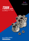
2.5 TD6N形 お客様の使用環境に合わせた
HCブレーカ 工具が選択できます
TD6N
2 HC Breaker Select the suitable tool for your usage
environment.
1.5
1 TD6N形
FC/FB
ブレーカ
TD6N TR4F形0.5 FC/FB Breaker TR4F type
0
0 0.5 1 1.5 2 2.5 3
1刃当りの送り量 fz Feed per tooth (mm/t)
0
0 2000 4000 6000 8000 10000
テーブル送り量 v f Feed speed (mm/min)
※被削材 Work material:S50C(220HB)、使用機械 Machine:縦型3軸M/C(BT50主軸 22kw) 3-axis MC vertical type(BT50,22kw)、
工具径 Tool dia.:Φ63、刃数 No. of Flutes:5枚刃 5 Flutes 、切削速度 Cutting Speed:150m/min
TR4F形 TD6N形
TR4F type TD6N type
外径:Φ32~100 外径:Φ50~125
Tool dia. Tool dia.
刃数:2~8枚刃 刃数:3~8枚刃
No. of Flutes : 2-8 Flutes No. of Flutes : 3-8 Flutes
●4コーナの経済性を持ちつつf z=2.0mm/tを超え ●インサートに高送りタイプ(FC/FB)と高切込み
る高送り加工に対応 タイプ(HC)をラインナップ
●等高線加工だけでなく、バーチカル加工も可能な ●同一ボディに2種類のインサートを取り付けられ、
多用途型 幅広い領域に対応可能な汎用型
・ Corresponds to high-feed cutting exceeding fz = 2.0 mm/t, ・ Lineup of high-feed type (FC/FB) and high depth type (HC)
with economical four-corner insert. for inserts
・ Multi-purpose type capable of both vertical and contour ・ General-purpose type allows attachment of two types of
cutting inserts to one body to meet a broad range of cutting needs.
14
軸方向切込み量 ap Axial depth of cut (mm)
in
3 /m
00c
m
Q=4
Page15
当社高送り工具のラインナップ High-feed tools lineup
3 豊富な工具ラインナップであらゆる荒加工のニーズに対応します。 Application Matrix: Rough Machining
特長 ボディ インサート
Feature Body Insert
プログラミ
2.5 TD6N形 お客様の使用環境に合わせた 型式
p
経済性 高精度 高硬度 能率 ング R
最大 a
Type Maximum ap(コーナ数) (削り残し小) 対応 (刃数) 外径 コーナ数 形状 内接円記号 Programming R
HCブレーカ Tool dia. Inscribed
(mm)
工具が選択できます Economical high accuracy Supports for high- Efficiency (mm)(mm) No. of corners Shape circle code(No. of corners) (Less uncut remnants) hardened steel (No. of Flutes)
TD6N
2 HC Breaker Select the suitable tool for your usage
environment. ◎
TD4N ◎ ◎ 〜50HRC 高能率多刃 φ16〜42 4 06 2.0 1.0
High Efficiency
multiflutes
1.5
06 2.0 1.5
ASR 多刃 ○ ○
◎
高能率多刃
〜62HRC φ16〜66 2TD6N形 Multi-Flutes High Efficiency 1 multiflutes 12 3.0 2.0
FC/FB
ブレーカ
TD6N TR4F形 ○ASRF mini ◎ ○0.5 FC/FB Breaker TR4F type 〜62HRC 汎用 φ20〜63 4 07 2.0 1.2General
○
0 ○
0 0.5 1 1.5 2 2.5 3 ASR ○ 〜60HRC 汎用 φ20〜100 2 08〜15General
1刃当りの送り量 fz Feed per tooth (mm/t) 3.0
0 ○ ○
0 2000 4000 6000 8000 10000 ASRT ○ ○ 〜62HRC 汎用 φ25〜100 3 09〜14 2.0General
テーブル送り量 v f Feed speed (mm/min)
○
※被削材 Work material:S50C(220HB)、使用機械 Machine:縦型3軸M/C(BT50主軸 22kw) 3-axis MC vertical type(BT50,22kw)、 ASRF ◎ ○
:Φ63、刃数 :5枚刃 、切削速度 :150m/min 〜60HRC
汎用 φ32〜100 4 12 4.5
工具径 Tool dia. No. of Flutes 5 Flutes Cutting Speed General
1.5
○
TD6N ○ 〜50HRC 汎用 φ50〜125 6 14
General
3.0 3.0
◎
TR4F ◎ ○ 高能率多刃〜60HRC φ32〜100 4 12 1.2High Efficiency
multiflutes
※上記以外にも荒加工用工具を多数ラインナップしております。
※工具仕様の詳細については総合カタログまたはホームページで確認をお願いします。
Various other tools for roughing are also available.
For more information on tool specifications, please refer to our general catalog or visit our website.( http://www.moldino.com)
15
軸方向切込み量 ap Axial depth of cut (mm)
in
3 /m
m
00c
Q=4
Page16
図、表等のデータは試験結果の一例であり、保証値ではありません。
「 」は株式会社MOLDINOの登録商標です。
The diagrams and table data are examples of test results, and are not guaranteed values.
“ ” is a registered trademark of MOLDINO Tool Engineering, Ltd.
安 全 上 の ご 注 意 Attentions on Safety
1. 取扱上のご注意 1. Attentions regarding handling
(1)工具をケース(梱包)から取り出す際は、足元への落下あるいは素手の指先へ落して怪我をしないよ (1) When removing the tool from the case (package), be careful not to drop it on your foot or
うに十分なご注意をお願いします。 drop it onto the tips of your bare fingers.
(2)インサートをセットして実際にご使用する場合は、切れ刃を素手で直接触れないように注意してください。 (2) When actually setting the inserts, be careful not to touch the cutting flute directly with
2. 取付け時のご注意 your bare hands.
(1)ご使用にあたって、インサートのセッティングは確実に行っていただき、アーバ等への取付けも確実に 2. Attentions regarding mounting
行ってください。 (1) When preparing for use, be sure that the inserts are firmly mounted in place and that they
(2)ご使用中に、異常な振動等が発生した場合は、直ちに機械を停止させて、その振動の原因を除いて are firmly mounted on the arbor, etc.
ください。 (2) If abnormal chattering occurs during use, stop the machine immediately and remove the cause of the chattering.
3. 使用上のご注意
(1)切削工具あるいは被削材の寸法・回転の方向は、あらかじめ確認しておいてください。 3. Attentions during use(1) Before use, confirm the dimensions and direction of rotation of the tool and milling work
(2)標準切削条件表の数値は、新しい作業の立上げの目安としてご利用ください。切込みが大きい場合、 material.
使用機械の剛性が小さい場合あるいは被加工物の性状に応じて切削条件を適正に調整してご使用 (2) The numerical values in the standard cutting conditions table should be used as criteria when
ください。 starting new work. The cutting conditions should be adjusted as appropriate when the cutting
(3)インサートは硬質の材料です。ご使用中に破損して飛散する場合があります。また、切りくずが飛散す depth is large, the rigidity of the machine being used is low, or according to the conditions of
ることがあります。これらの飛散物等は作業者を切傷させ、火傷あるいは目に入って負傷させる恐れが the work material.
ありますので、工具をご使用中はその周囲に安全カバーを取付け、保護めがね等の保護具を着用し (3) The inserts are made of a hard material. During use, they may break and fly off. In addition,
て安全な環境下での作業をお願いいたします。 cutting chips may also fly off. Since there is a danger of injury to workers, fire, or eye damage
・引火や爆発の危険のあるところでは使用しないでください。 from such flying pieces, a safety cover should be installed and safety equipment such as
・不水溶性切削油は、火災の恐れがありますので使用しないでください。 safety glasses should be worn to create a safe environment for work.
(4)工具を本来の目的以外に使用したり、改造したりしないでください。 ・Do not use where there is a risk of fire or explosion. ・Do not use non-water-soluble cutting oils. Such oils may result in fire.
4. 工具に関して、安全上の問題点・不明の点・その他ご相談がありましたら フリーダイヤル技術相談 へ (4) Do not use the tool for any purpose other than that for which it is intended, and do not modify it.
お問い合わせください。
ホームページ フリーダイヤル技術相談
http://www.moldino.com
MOLDINO Tool Engineering, Ltd.
本社 〒130-0026 東京都墨田区両国4-31-11(ヒューリック両国ビル8階) 工具選定データベース【 TOOL SEARCH】
03-6890-5101 FAX 03-6890-5134
International Sales Dept .: +81-3-6890-5103 FAX +81-3-6890-5128
営業企画部 ☎03-6890-5102 FAX03-6890-5134 海外営業部 ☎03-6890-5103 FAX03-6890-5128
東京営業所 ☎03-6890-5110 FAX03-6890-5133 静岡営業所 ☎054-273-0360 FAX054-273-0361
東北営業所 ☎022-208-5100 FAX022-208-5102 名古屋営業所 ☎052-687-9150 FAX052-687-9144
新潟営業所 ☎0258-87-1224 FAX0258-87-1158 大阪営業所 ☎06-7668-0190 FAX06-7668-0194
東関東営業所 ☎0294-88-9430 FAX0294-88-9432 中四営業所 ☎082-536-2001 FAX082-536-2003
長野営業所 ☎0268-21-3700 FAX0268-21-3711 九州営業所 ☎092-289-7010 FAX092-289-7012
北関東営業所 ☎0276-59-6001 FAX0276-59-6005 北九州営業所 ☎093-434-2640 FAX093-434-6846
神奈川営業所 ☎046-400-9429 FAX046-400-9435
ヨーロッパ/MOLDINO Tool Engineering Europe GmbH Itterpark 12, 40724 Hilden, Germany. TEL : +49-(0)2103-24820, FAX : +49-(0)2103-248230
中 国/MOLDINO Tool Engineering, (Shanghai) Ltd. Room 2604-2605, Metro Plaza, 555 Loushanguan Road, Changning Disctrict, Shanghai, 200051, CHINA TEL:+86-(0)21-3366-3058, FAX:+86-(0)21-3366-3050
アメリカ/MITSUBISHI MATERIALS U.S.A. CORPORATION 41700 Gardenbrook Road, Suite 120, Novi, MI 48375-1320 U.S.A. TEL : +1(248)308-2620, FAX :+1(248)308-2627
メキシコ/MMC METAL DE MEXICO, S.A. DE C.V. Av. La Cañada No.16, Parque Industrial Bernardo Quintana, El Marques, Querétaro, CP 76246, México TEL : +52-442-1926800
ブラジル/MMC METAL DO BRASIL LTDA. Rua Cincinato Braga, 340 13° andar.Bela Vista – CEP 01333-010 São Paulo – SP ., Brasil TEL : +55(11)3506-5600 FAX : +55(11)3506-5677
タ イ/MMC Hardmetal (Thailand) Co.,Ltd. MOLDINO Division 622 Emporium Tower, Floor 22/1-4, Sukhumvit Road, Klong Tan, Klong Toei, Bangkok 10110, Thailand TEL:+66-(0)2-661-8175 FAX:+66-(0)2-661-8176
イ ン ド/Hitachi Metals (India) Pvt. Ltd. Plot No 94 & 95,Sector 8, IMT Manesar, Gurgaon -122050, Haryana, India TEL : +91-124-4812315, FAX :+91-124-2290015
掲載価格は消費税抜きの単価を表示しております。予告なく、改良・改善のために仕様変更することがあります。
Specifications for the products listed in this catalog are subject to change without notice due to ベジタブルインクで印刷しています。 2020-11(ME-HKT3)
replacement or modification. Printed using vegetable oil ink. Printed in JAPAN 2020-4:FP