


ますます話題!異形工具が広まりつつあります!
関連メディア
このカタログについて
| ドキュメント名 | 異形工具シリーズ GALLEA 形 |
|---|---|
| ドキュメント種別 | 製品カタログ |
| ファイルサイズ | 4.1Mb |
| 取り扱い企業 | 株式会社MOLDINO (この企業の取り扱いカタログ一覧) |
この企業の関連カタログ


このカタログの内容
Page1
高能率仕上げ加工用 異形工具シリーズ High Efficiency Finishing Special Shape Tool Series
ガレアシリーズ
GALLEA series
GP1LBに3軸でも使いやすい
コーナ接続R刃インサートを追加しました。
Added corner-connected R insert for GP1LB that easy to use for 3-axis machining.
図、表等のデータは試験結果の一例であり、保証値ではありません。
「 」は株式会社MOLDINOの登録商標です。
The diagrams and table data are examples of test results, and are not guaranteed values.
“ ” is a registered trademark of MOLDINO Tool Engineering, Ltd.
安 全 上 の ご 注 意 Attentions on Safety
1. 取扱上のご注意 1. Cautions regarding handling
(1)工具をケース(梱包)から取り出す際は、工具の飛び出し、落下にご注意ください。特に工具刃部との接 (1) When removing the tool from its case (packaging), be careful that the tool does not pop out or is
触には十分ご注意をお願いします。 dropped. Be particularly careful regarding contact with the tool flutes.
(2)鋭利な切れ刃を有する工具を取扱う際は、切れ刃を素手で直接触れないように注意してください。 (2) When handling tools with sharp cutting flutes, be careful not to touch the cutting flutes directly with
2. 取付け時のご注意 your bare hands.
(1)ご使用前に、工具の傷・割れ等の外観確認を行っていただき、コレットチャック等への取付けは確実に 2. Cautions regarding mounting
行ってください。 (1) Before use, check the outside appearance of the tool for scratches, cracks, etc. and that it is firmly
(2)ご使用にあたって、インサートのセッティングは確実に行っていただき、アーバ等への取付も確実に行っ mounted in the collet chuck, etc.
てください。 (2) When preparing for use, be sure that the inserts are firmly mounted in place and that they are firmily
(3)ご使用中に、異常な振動等が発生した場合は、直ちに機械を停止させて、その振動の原因を取り除い mounted on the arbor, etc.
てください。 (3) If abnormal chattering, etc. occurs during use, stop the machine immediately and remove the cause
3. 使用上のご注意 of the chattering.
(1)切削工具あるいは被削材の寸法・回転の方向は、あらかじめ確認しておいてください。 3. Cautions during use
(2)標準切削条件表の数値は、新しい作業の立上げの目安としてご利用ください。切込みが大きい場合、 (1) Before use, confirm the dimensions and direction of rotation of the tool and milling work material.
使用機械の剛性が小さい場合あるいは被加工物の性状に応じて切削条件を適正に調整してご使用 (2) The numerical values in the standard cutting conditions table should be used as criteria when starting
ください。 new work. The cutting conditions should be adjusted as appropriate when the cutting depth is large,
(3)切削工具材料は硬質の材料です。ご使用中に破損して飛散する場合があります。また、切りくずが飛 the rigidity of the machine being used is low, or according to the conditions of the work material.
散することがあります。これらの飛散物等は作業者を切傷させ、火傷あるいは目に入って負傷させる恐 (3) Cutting tools are made of a hard material. During use, they may break and fly off. In addition, cutting
れがありますので、工具をご使用中はその周囲に安全カバーを取付け、保護めがね等の保護具を着用 chips may also fly off. Since there is a danger of injury to workers, fire, or eye damage from such
して安全な環境下での作業をお願いいたします。 flying pieces, a safety cover should be attached when work is performed and safety equipment such
(4)切削中に発生する火花や、破損による発熱や、切りくずによる引火・火災の危険があります。引火や as safety goggles should be worn to create a safe environment for work.
爆発の危険のあるところでは使用しないでください。不水溶性切削液をご使用される場合は防火対 (4) There is a risk of fire or inflammation due to sparks, heat due to breakage, and cutting chips. Do not
策を必ず行なってください。 use where there is a risk of fire or explosion. Please caution of fire while using oil base coolant, fire
(5)工具を本来の目的以外にはご使用にならないでください。 prevention is necessary.
4. 再研削時のご注意 (5) Do not use the tool for any purpose other than that for which it is intended.
(1)再研削時期が不適当であると工具が破損する恐れがあります。適正な工具と交換するか、再研削を 4. Cautions regarding regrinding
行ってください。
(2)工具を再研削しますと粉塵が発生します。再研削時にはその周囲に安全カバーを取付け、保護め (1) If regrinding is not performed at the proper time, there is a risk of the tool breaking. Replace the tool
がね等の保護具を着用してください。 with one in good condition, or perform regrinding.
(3)本製品には特定化学物質に指定された コバルト及びその無機化合物が含まれています。再研削等の (2) Grinding dust will be created when regrinding a tool. When regrinding, be sure to attach a safety
加工を加える場合は特定化学物質障害予防規則(特化則)に従った取扱いをしてください。 cover over the work area and wear safety clothes such as safety goggles, etc.(3) This product contains the specified chemical substance cobalt and its inorganic compounds. When
5. 工具に関して、安全上の問題点・不明の点・その他相談がありましたら フ リ ーダ イ ヤ ル 技 術 相 談 へ performing regrinding or similar processing, be sure to handle the processing in accordance with
ご相談ください。 thelocal laws and regulations regarding prevention of hazards due to specified chemical substances.
ホームページ フリーダイヤル技術相談
http://www.moldino.com
MOLDINO Tool Engineering, Ltd.
本社 〒130-0026 東京都墨田区両国4-31-11(ヒューリック両国ビル8階) 工具選定データベース【 TOOL SEARCH】
03-6890-5101 FAX 03-6890-5134
International Sales Dept .: +81-3-6890-5103 FAX +81-3-6890-5128
営業企画部 ☎03-6890-5102 FAX03-6890-5134 海外営業部 ☎03-6890-5103 FAX03-6890-5128
東京営業所 ☎03-6890-5110 FAX03-6890-5133 静岡営業所 ☎054-273-0360 FAX054-273-0361
東北営業所 ☎022-208-5100 FAX022-208-5102 名古屋営業所 ☎052-687-9150 FAX052-687-9144
新潟営業所 ☎0258-87-1224 FAX0258-87-1158 大阪営業所 ☎06-7668-0190 FAX06-7668-0194
東関東営業所 ☎0294-88-9430 FAX0294-88-9432 中四営業所 ☎082-536-2001 FAX082-536-2003
長野営業所 ☎0268-21-3700 FAX0268-21-3711 九州営業所 ☎092-289-7010 FAX092-289-7012
北関東営業所 ☎0276-59-6001 FAX0276-59-6005 北九州営業所 ☎093-434-2640 FAX093-434-6846
神奈川営業所 ☎046-400-9429 FAX046-400-9435
ヨーロッパ/MOLDINO Tool Engineering Europe GmbH Itterpark 12, 40724 Hilden, Germany. TEL : +49-(0)2103-24820, FAX : +49-(0)2103-248230
中 国/MOLDINO Tool Engineering, (Shanghai) Ltd. Room 2604-2605, Metro Plaza, 555 Loushanguan Road, Changning Disctrict, Shanghai, 200051, CHINA TEL:+86-(0)21-3366-3058, FAX:+86-(0)21-3366-3050
アメリカ/MITSUBISHI MATERIALS U.S.A. CORPORATION 41700 Gardenbrook Road, Suite 120, Novi, MI 48375-1320 U.S.A. TEL : +1(248)308-2620, FAX :+1(248)308-2627
メキシコ/MMC METAL DE MEXICO, S.A. DE C.V. Av. La Cañada No.16, Parque Industrial Bernardo Quintana, El Marques, Querétaro, CP 76246, México TEL : +52-442-1926800 MOLDINO Tool Engineering, Ltd.
ブラジル/MMC METAL DO BRASIL LTDA. Rua Cincinato Braga, 340 13° andar.Bela Vista – CEP 01333-010 São Paulo – SP ., Brasil TEL : +55(11)3506-5600 FAX : +55(11)3506-5677
タ イ/MMC Hardmetal (Thailand) Co.,Ltd. MOLDINO Division 622 Emporium Tower, Floor 22/1-4, Sukhumvit Road, Klong Tan, Klong Toei, Bangkok 10110, Thailand TEL:+66-(0)2-661-8175 FAX:+66-(0)2-661-8176
イ ン ド/Hitachi Metals (India) Pvt. Ltd. Plot No 94 & 95,Sector 8, IMT Manesar, Gurgaon -122050, Haryana, India TEL : +91-124-4812315, FAX :+91-124-2290015 New Produc t News No.1711-5 2020-10
掲載価格は消費税抜きの単価を表示しております。予告なく、改良・改善のために仕様変更することがあります。
Specifications for the products listed in this catalog are subject to change without notice due to ベジタブルインクで印刷しています。 2020-10(K)
replacement or modification. Printed using vegetable oil ink. Printed in JAPAN 2017-10:FP
Page2
曲 面 斬り三 刃 流 5シ
Series
シリーズ 3-edge, curved surface cutting 軸ー GS4TN
加ム
GF3L 工レ
GF1 へス
の
懸
GP1LB け
レンズ Rと GP1T 橋
GF2T バレルR の融 合
Seamless High efficiency
Combination of lens tool and barrel tool for 5-axis machining
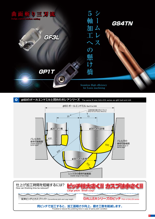
ガレアシリーズのコンセプト φ60のボールエンドミルと同Rのガレアシリーズ The same R size GALLEA series as φ60 ball end mill.
Concept of GALLEA series φ60 ボールエンドミル Ball End Mill
工具半径の差分をオフセット
Offset the tool radius difference.
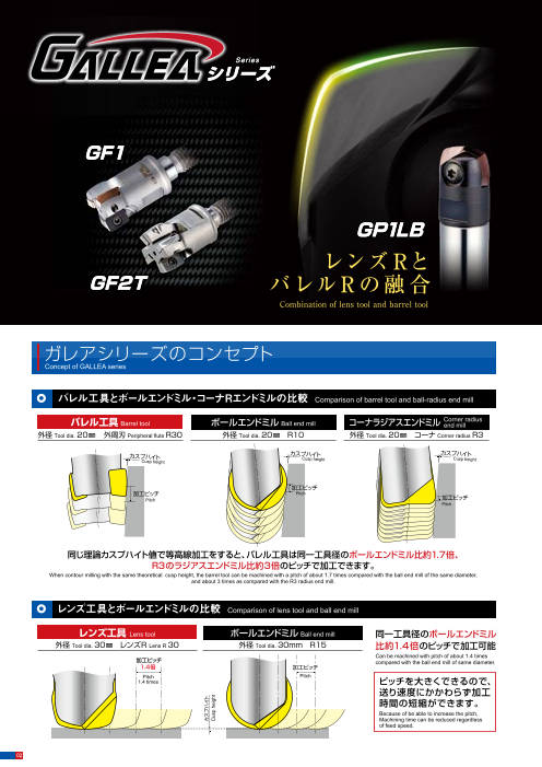
バレル工具とボールエンドミル・コーナRエンドミルの比較 Comparison of barrel tool and ball-radius end mill
20 15
バレル工具 Barrel tool ボールエンドミル Ball end mill コーナラジアスエンドミル Corner radius end mill
外径 Tool dia. 20㎜ 外周刃 Peripheral flute R30 外径 Tool dia. 20㎜ R10 外径 Tool dia. 20㎜ コーナ Corner radius R3
カスプハイト カスプハイト φ20 GF1形 φ30 GP1LB 形カスプハイト
Cu Csp u sh pe i hg eh it ght
Cusp height
加工ピッチ バレル刃の R30
加工ピッチ Pitch 使用可能範囲 バレル刃の Pitch 加工ピッチ
Pitch Usable range of 使用可能範囲
barrel egde. R30 Usable range of
barrel edge.
R3
0
同じ理論カスプハイト値で等高線加工をすると、バレル工具は同一工具径のボールエンドミル比約1.7倍、 φ30 GP1LB 形
R3のラジアスエンドミル比約3倍のピッチで加工できます。
When contour milling with the same theoretical cusp height, the barrel tool can be machined with a pitch of about 1.7 times compared with the ball end mill of the same diameter,
and about 3 times as compared with the R3 radius end mill.
レンズ工具とボールエンドミルの比較 Comparison of lens tool and ball end mill レンズ刃の使用可能範囲
Usable range of lens edge.
レンズ工具 Lens tool ボールエンドミル Ball end mill 同一工具径のボールエンドミル
外径 Tool dia. 30㎜ レンズR Lens R 30 外径 Tool dia. 30mm R15 比約1.4倍のピッチで加工可能 仕上げ加工時間を短縮するには?
Can be machined with pitch of about 1.4 times ピッチは大きく!! カスプは小さく!!
加工ピッチ compared with the ball end mill of same diameter. How can finishing time be reduced?
1.4倍 加工ピッチ Large pitch! Small cusp!
Pitch Pitch
1.4 times ピッチを大きくできるので、
送り速度にかかわらず加工 従来ピッチとカスプハイト Conventional pitch and cusp height GALLEAシリーズのピッチ Pitch of GALLEA series
時間の短縮ができます。
Because of be able to increase the pitch,
Machining time can be reduced regardless
of feed speed. 同ピッチで加工すると、加工面粗さが向上。磨き工数を削減します。
Possible to reduce the polishing time in case of same pitch condition
02 03
カスプハイト
Cusp height
0
R3
Page3
曲 面 斬り三 刃 流 5シ
Series
シリーズ 3-edge, curved surface cutting 軸ー GS4TN
加ム
GF3L 工レ
GF1 へス
の
懸
GP1LB け
レンズ Rと GP1T 橋
GF2T バレルR の融 合
Seamless High efficiency
Combination of lens tool and barrel tool for 5-axis machining
ガレアシリーズのコンセプト φ60のボールエンドミルと同Rのガレアシリーズ The same R size GALLEA series as φ60 ball end mill.
Concept of GALLEA series φ60 ボールエンドミル Ball End Mill
工具半径の差分をオフセット
Offset the tool radius difference.
バレル工具とボールエンドミル・コーナRエンドミルの比較 Comparison of barrel tool and ball-radius end mill
20 15
バレル工具 Barrel tool ボールエンドミル Ball end mill コーナラジアスエンドミル Corner radius end mill
外径 Tool dia. 20㎜ 外周刃 Peripheral flute R30 外径 Tool dia. 20㎜ R10 外径 Tool dia. 20㎜ コーナ Corner radius R3
カスプハイト カスプハイト φ20 GF1形 φ30 GP1LB 形カスプハイト
Cu Csp u sh pe i hg eh it ght
Cusp height
加工ピッチ バレル刃の R30
加工ピッチ Pitch 使用可能範囲 バレル刃の Pitch 加工ピッチ
Pitch Usable range of 使用可能範囲
barrel egde. R30 Usable range of
barrel edge.
R3
0
同じ理論カスプハイト値で等高線加工をすると、バレル工具は同一工具径のボールエンドミル比約1.7倍、 φ30 GP1LB 形
R3のラジアスエンドミル比約3倍のピッチで加工できます。
When contour milling with the same theoretical cusp height, the barrel tool can be machined with a pitch of about 1.7 times compared with the ball end mill of the same diameter,
and about 3 times as compared with the R3 radius end mill.
レンズ工具とボールエンドミルの比較 Comparison of lens tool and ball end mill レンズ刃の使用可能範囲
Usable range of lens edge.
レンズ工具 Lens tool ボールエンドミル Ball end mill 同一工具径のボールエンドミル
外径 Tool dia. 30㎜ レンズR Lens R 30 外径 Tool dia. 30mm R15 比約1.4倍のピッチで加工可能 仕上げ加工時間を短縮するには?
Can be machined with pitch of about 1.4 times ピッチは大きく!! カスプは小さく!!
加工ピッチ compared with the ball end mill of same diameter. How can finishing time be reduced?
1.4倍 加工ピッチ Large pitch! Small cusp!
Pitch Pitch
1.4 times ピッチを大きくできるので、
送り速度にかかわらず加工 従来ピッチとカスプハイト Conventional pitch and cusp height GALLEAシリーズのピッチ Pitch of GALLEA series
時間の短縮ができます。
Because of be able to increase the pitch,
Machining time can be reduced regardless
of feed speed. 同ピッチで加工すると、加工面粗さが向上。磨き工数を削減します。
Possible to reduce the polishing time in case of same pitch condition
02 03
カスプハイト
Cusp height
0
R3
Page4
GALLEAシリーズ一覧
List of GALLEA ser ies
赤 バレル刃の3軸加工における使用可能範囲 青 レンズ刃、先端刃の3軸加工における使用可能範囲 緑 コーナ接続R刃の3軸加工における使用可能範囲 Red : In 3-axis machining usable range of Barrel edge Blue : In 3-axis machining usable range of Lens edge / Tip edge Green : In 3-axis machining usable range of corner-connected R GALLEAシリーズの使い分け
GF1 バレル P.6 Overview of GALLEA seriesBarrel
仕上げ加工時間
90° 90° 70%短縮!! SKD11Ⓗ プレス金型(隅部) プレス金型(壁面、緩曲面)
Finishing machining time Stamping die (Corner) Stamping die (Wall surface, gently-curved surface)
reduced by 70% 鍛
バレルR
Barrel R φ20㎜ R1 コーナラジアスミル GALLEA GF1 造
79°(GF1G) 83°(GF1G) φ20mm R1 Corner radius end mill 最外径φ20mm 外周刃30R ・
0° 71°(GF1T) 0° 78°(GF1T) Max. external diameter φ20mm Outer peripheral flute 30R【切削条件】 プCutting conditions
R20 R30 【切削条件】Cutting conditionsvf=2000mm/min n=4500min-1 ap=0.2mm vf=2000mm/min n=4500min-1 ap=0.6mm プリハードン鋼 ラ
勾配面の加工 加工時間シミュレーション=約150分For tilted wall finishing Machining time simulation = Approx. 150 min. 加工時間=約40分 Cutting time = Approx. 40 min. Pre-hardened steel スチ
ッ プラスチック金型(壁面、緩曲面、隅部)
GF2T バレル ク Plastic mold (Wall surface, gently-curved surface and corner)Barrel P.8 高能率な傾斜壁面の仕上げ加工 ! High-performance tilted wall finishing! 金 ダイキャスト金型 Die casting dies
ボールエンドミル、ラジアスエンドミルに比べ大ピッチで加工可能です。 型
90° (Enables machining at a larger pitch than ball end mills or radius end mills. 壁・ ブリスク、インペラー、タービンブレード(翼形状)
75.1°(φ20) 大径側にシリーズ展開しました ! Series expansion toward larger diameters 隅 Blisk, Impeller, Turbine blade (Blade shape)
75.0°(φ25)
74.8°(φ35) バレルR φ20 φ25 φ35 φ40 部
74.7°(φ40) Barrel R )
0° 経済的な2コーナ仕様! Economical 2-corner specification
ユニークなインサート拘束面により2コーナ仕様を実現しました。 機械構造部
勾配面の加工 Unique insert holding surface enables realization of 2-corner specification. 部品・金型(タイヤ金型、バスタブ) For tilted wall finishing Parts, Die mold (Tire mold, Bathtub) Machine structual conponents
GF3L レンズLens P.10 01 GALLEAシリーズ(GF3L形とGP1LB形)を合わせて使用することで 炭素鋼Carbon steel
中仕上げ~仕上げ加工の高能率化が図れます。
90° 90° Using GALLEA series together it is possible to process from semi-finishing to finishing with プレス金型(隅部)
high efficiency Stamping die (Corner) プレス金型(壁面、緩曲面)
レンズR Stamping die
Lens R 02 切れ味良好なポジ設計 Good sharpness positive design (Wall surface, gently-curved surface)
18° 22° 03 高能率な3枚刃仕様 High efficiency cutting tool with three edge specification
FC/FCD
0° 0° 4° 鋳鉄
中仕上げ 仕上げ
Semi-finishing Finishing 04 ユニークなインサート拘束面が強固なインサートクランプを実現する。 Cast iron
緩曲面・緩斜面の加工 For gentle curved surfaces and Unique insert restraining surface realizes strong insert clamping.gentle sloped surfaces 20mm 30mm
GP1LB バレル・レンズ 工具直径 Tool diameterBarrel, Lens P.12 レンズ工具とバレル工具の融合!! プレシジョンタイプ
Combination of lens tool and barrel tool. Precision type
90° 90° GP1LB 形
type GALLEA 外径・バレルRマップ
68° レンズ工具 バレル工具 Chart of tool dia. and barrel for GALLEA seriesLens tool Barrel tool
バレルR
72.22°(φ16) Barrel R + バ
69.92°(φ レ20) =レンズR ル 外径 Tool dia.(mm)
22° 73.79°(φ25) Lens R R バレルR 2.5 3.75 5.0 7.5 10.0 12.0 16.0 20.0 25.0 30.0 35.0 40.00° 0° 13° 77.15°(φ30) Barrel R (mm)レンズR Lens R
ZPHW○○○-LB○○ ZPHW○○○-LB○○-R○○ コーナ接続R 12.5 GS4TN
Corner-connected R なだらかな曲面 壁面 一本で加工可能
勾配面・曲面の加工 For tilted wall and curved surface finishing Gently curved surface Wall surface Can be machined with a single tool. 16.0 GP1LB
18.75 GS4TN
GP1T テーパバレル 5軸加工のメリットを最大限活かす1つの工具で2種類の加工 19.91 GF1TTaper Barrel P.14 工具交換無しで加工できるので、加工段差が最小限に。 19.93 GF1G
Two types of process are possible with one tool that can fully utilize the merit of 5-axis machining GF1T/GF1G
90° Since it can work for 2 types of process without tool change, machining surface steps can be minimized. 20.0 GP1LB
20.14 GF1G
64° バレルR 20.18 GF1T
Barrel R
47° 25.0 GS4TN GP1LB
先端R
0° 29.78 GF2TTip R
バレルR Barrel R 先端R Tip R 29.81 GF1T
勾配面・曲面・隅Rの加工 For tilted wall, curved surface 工具半径より大きなバレルRでピッチを大きくできます。 隅部の加工に、先端をボールエンドミルとして使用可。and corner finishing This tool can take a larger pitch with a barrel R which larger than the tool radius. The tip can be used as a ball end mill for corner processing. 29.82 GF1G
29.84 GF2T
GS4TN 接線バレル P.18 30.0 GP1T GF1T/GF1G GF2T GP1LBTangent Barrel ・外周のバレルR刃は勾配面を高能率・高品位に! 30.24 GF2T
90° ・先端R刃は曲面の接続面を高品位に! 30.33 GF1T
・独特な強ねじれ刃形状を採用、低抵抗化を実現! 30.38 GF1G
バレルR
69.636° Barrel R 37.5 GS4TN・Barrel R achieves high-efficiency and high-quality machining for tilted section
先端R ・Tip R can finish curved connecting faces to high quality 40.0 GP1T
Tip R
0° ・Employs unique high helix shape and realizes low cutting force 50.0 GS4TN GP1T
62.5 GP1T
勾配面・曲面・隅Rの加工 For tilted wall, curved surfaceand corner finishing 75.0 GP1T
04 05
Barrel R
被削材硬さ Work Hardness
Forging die and plastic mold (Wall surface, corner)
GS4TN GP1T GP1LB GF3L GF2T GF1
Page5
GALLEAシリーズ一覧
List of GALLEA ser ies
赤 バレル刃の3軸加工における使用可能範囲 青 レンズ刃、先端刃の3軸加工における使用可能範囲 緑 コーナ接続R刃の3軸加工における使用可能範囲 Red : In 3-axis machining usable range of Barrel edge Blue : In 3-axis machining usable range of Lens edge / Tip edge Green : In 3-axis machining usable range of corner-connected R GALLEAシリーズの使い分け
GF1 バレル P.6 Overview of GALLEA seriesBarrel
仕上げ加工時間
90° 90° 70%短縮!! SKD11Ⓗ プレス金型(隅部) プレス金型(壁面、緩曲面)
Finishing machining time Stamping die (Corner) Stamping die (Wall surface, gently-curved surface)
reduced by 70% 鍛
バレルR
Barrel R φ20㎜ R1 コーナラジアスミル GALLEA GF1 造
79°(GF1G) 83°(GF1G) φ20mm R1 Corner radius end mill 最外径φ20mm 外周刃30R ・
0° 71°(GF1T) 0° 78°(GF1T) Max. external diameter φ20mm Outer peripheral flute 30R【切削条件】 プCutting conditions
R20 R30 【切削条件】Cutting conditionsvf=2000mm/min n=4500min-1 ap=0.2mm vf=2000mm/min n=4500min-1 ap=0.6mm プリハードン鋼 ラ
勾配面の加工 加工時間シミュレーション=約150分For tilted wall finishing Machining time simulation = Approx. 150 min. 加工時間=約40分 Cutting time = Approx. 40 min. Pre-hardened steel スチ
ッ プラスチック金型(壁面、緩曲面、隅部)
GF2T バレル ク Plastic mold (Wall surface, gently-curved surface and corner)Barrel P.8 高能率な傾斜壁面の仕上げ加工 ! High-performance tilted wall finishing! 金 ダイキャスト金型 Die casting dies
ボールエンドミル、ラジアスエンドミルに比べ大ピッチで加工可能です。 型
90° (Enables machining at a larger pitch than ball end mills or radius end mills. 壁・ ブリスク、インペラー、タービンブレード(翼形状)
75.1°(φ20) 大径側にシリーズ展開しました ! Series expansion toward larger diameters 隅 Blisk, Impeller, Turbine blade (Blade shape)
75.0°(φ25)
74.8°(φ35) バレルR φ20 φ25 φ35 φ40 部
74.7°(φ40) Barrel R )
0° 経済的な2コーナ仕様! Economical 2-corner specification
ユニークなインサート拘束面により2コーナ仕様を実現しました。 機械構造部
勾配面の加工 Unique insert holding surface enables realization of 2-corner specification. 部品・金型(タイヤ金型、バスタブ) For tilted wall finishing Parts, Die mold (Tire mold, Bathtub) Machine structual conponents
GF3L レンズLens P.10 01 GALLEAシリーズ(GF3L形とGP1LB形)を合わせて使用することで 炭素鋼Carbon steel
中仕上げ~仕上げ加工の高能率化が図れます。
90° 90° Using GALLEA series together it is possible to process from semi-finishing to finishing with プレス金型(隅部)
high efficiency Stamping die (Corner) プレス金型(壁面、緩曲面)
レンズR Stamping die
Lens R 02 切れ味良好なポジ設計 Good sharpness positive design (Wall surface, gently-curved surface)
18° 22° 03 高能率な3枚刃仕様 High efficiency cutting tool with three edge specification
FC/FCD
0° 0° 4° 鋳鉄
中仕上げ 仕上げ
Semi-finishing Finishing 04 ユニークなインサート拘束面が強固なインサートクランプを実現する。 Cast iron
緩曲面・緩斜面の加工 For gentle curved surfaces and Unique insert restraining surface realizes strong insert clamping.gentle sloped surfaces 20mm 30mm
GP1LB バレル・レンズ 工具直径 Tool diameterBarrel, Lens P.12 レンズ工具とバレル工具の融合!! プレシジョンタイプ
Combination of lens tool and barrel tool. Precision type
90° 90° GP1LB 形
type GALLEA 外径・バレルRマップ
68° レンズ工具 バレル工具 Chart of tool dia. and barrel for GALLEA seriesLens tool Barrel tool
バレルR
72.22°(φ16) Barrel R + バ
69.92°(φ レ20) =レンズR ル 外径 Tool dia.(mm)
22° 73.79°(φ25) Lens R R バレルR 2.5 3.75 5.0 7.5 10.0 12.0 16.0 20.0 25.0 30.0 35.0 40.00° 0° 13° 77.15°(φ30) Barrel R (mm)レンズR Lens R
ZPHW○○○-LB○○ ZPHW○○○-LB○○-R○○ コーナ接続R 12.5 GS4TN
Corner-connected R なだらかな曲面 壁面 一本で加工可能
勾配面・曲面の加工 For tilted wall and curved surface finishing Gently curved surface Wall surface Can be machined with a single tool. 16.0 GP1LB
18.75 GS4TN
GP1T テーパバレル 5軸加工のメリットを最大限活かす1つの工具で2種類の加工 19.91 GF1TTaper Barrel P.14 工具交換無しで加工できるので、加工段差が最小限に。 19.93 GF1G
Two types of process are possible with one tool that can fully utilize the merit of 5-axis machining GF1T/GF1G
90° Since it can work for 2 types of process without tool change, machining surface steps can be minimized. 20.0 GP1LB
20.14 GF1G
64° バレルR 20.18 GF1T
Barrel R
47° 25.0 GS4TN GP1LB
先端R
0° 29.78 GF2TTip R
バレルR Barrel R 先端R Tip R 29.81 GF1T
勾配面・曲面・隅Rの加工 For tilted wall, curved surface 工具半径より大きなバレルRでピッチを大きくできます。 隅部の加工に、先端をボールエンドミルとして使用可。and corner finishing This tool can take a larger pitch with a barrel R which larger than the tool radius. The tip can be used as a ball end mill for corner processing. 29.82 GF1G
29.84 GF2T
GS4TN 接線バレル P.18 30.0 GP1T GF1T/GF1G GF2T GP1LBTangent Barrel ・外周のバレルR刃は勾配面を高能率・高品位に! 30.24 GF2T
90° ・先端R刃は曲面の接続面を高品位に! 30.33 GF1T
・独特な強ねじれ刃形状を採用、低抵抗化を実現! 30.38 GF1G
バレルR
69.636° Barrel R 37.5 GS4TN・Barrel R achieves high-efficiency and high-quality machining for tilted section
先端R ・Tip R can finish curved connecting faces to high quality 40.0 GP1T
Tip R
0° ・Employs unique high helix shape and realizes low cutting force 50.0 GS4TN GP1T
62.5 GP1T
勾配面・曲面・隅Rの加工 For tilted wall, curved surfaceand corner finishing 75.0 GP1T
04 05
Barrel R
被削材硬さ Work Hardness
Forging die and plastic mold (Wall surface, corner)
GS4TN GP1T GP1LB GF3L GF2T GF1
Page6
GF1形
GF1 type
モジュラータイプ Modular type 標準切削条件表 Recommended cutting conditions
GF1 20 M- -M は数字、 は英文字が入ります。 ※赤字は第一推奨材種です。Red indicates primary recommended grade.Numeric figure in a circle and Alphabetical character comes in a square 推奨材種 ap値は所望のカスプハイトにより下記表より選択または下記計算式被削材 切削条件
Lf L2 Lf L2 E(切欠部巾) Work material Recommendedgrade Cutting condition
φ16 φ20 φ25 より算出してください
C L 1 C L1 M Notch width Determine the ap value based on the desired cusp height by selecting it from M n (min-1) 11,950 9,560 7,650
炭素鋼 the table below or by calculating it using the equation below.vc (m/min)
Carbon steels 600 600 600 ※
合金鋼 vf (mm/min)PN215 4,780 5,740 6,120 インサート カスプハイト (mm)
Alloy steels fz(mm/t) 0.2 0.2 0.2 Insert Cusp height
ap (mm) 右表を参照ください。Refera a ( <30HRC) right table 商品コードp p Item code R 0.001 0.002 0.003 0.004 0.005 0.01ae (mm) ~0.1 ~0.1 ~0.1
ベーシックタイプ Basic type オフセットタイプ Offset type n (min-1) 7,970 6,370 5,100
炭素鋼 XPHW0903R-20 20 0.4 0.57 0.69 0.8 0.89 1.26vc (m/min)
希望小売 Carbon steels 400 400 400 XPHW0903R-30 30 0.49 0.69 0.85 0.98 1.1 1.55
タイプ 商品コード 在庫 刃数 寸法 Size (mm) 使用インサート 価格(円) 合金鋼 PN215 vf (mm/min) 3,190 3,830 4,080
Type Item code Stock No.offlutes φDc Lf ap φD2 M φDb L L C E Insert1 2 Suggested Alloy steels TH315 fz(mm/t) 0.2 0.2 0.2 retail price(¥) HRefer
(30~45HRC) ap (mm) 右表を参照ください。right table ap= 2 (R2-(R-H)2)
GF1G2016M-2-M8 ● 2 16 25 9.5 8.5 M8 14 5.5 17 8 10 32,130 ae (mm) ~0.1 ~0.1 ~0.1
ベーシック GF1G2020M-3-M10 ● 3 20 30 9.5 10.5 M10 17.8 5.5 19 10 15 XPHW0903R-20 41,420 n (min
-1) 9,960 7,970 6,370 R: 工具R H:カスプハイト Tool R Cusp height
タイプ ap
※1GF1G2025M-4-M10 ● 4 25 30 9.5 10.5 M10 17.8 5.5 19 10 15 XPHW0903R-30
vc (m/min)
Basic type 49,980 ステンレス鋼
500 500 500
vf (mm/min)
● 22 10 17 Stainless steels
3,990 4,790 5,100 R
GF1G2025M-4-M12 4 25 35 9.5 12.5 M12 22.5 5.5 49,980 PN215SUS fz(mm/t) 0.2 0.2 0.2
オフセット GF1T2016M-2-M8 ● 2 16 25 9.5 8.5 M8 14 5.5 17 8 10 32,130
ap (mm) 右表を参照ください。Referright table
ae (mm)
タイプ GF1T2020M-3-M10 ● 3 20 30 9.5 10.5 M10 17.8 5.5 19 10 15 YPHW0903R-20 41,420
~0.1 ~0.1 ~0.1
YPHW0903R-30 n (min-1)
Offset type 11,950 9,560 7,650 ※突き出し長さ3Dc以上の場合は、左記の表をもとに下記表を参考GF1T2025M-4-M12 ● 4 25 35 9.5 12.5 M12 22.5 5.5 22 10 17 49,980 鋳鉄 vc (m/min) 600 600 600 に調整してください。
【注意】※1と※2(P.16)をセットで使用すると干渉がありません。 Cast iron TH315 vf (mm/min) 5,980 7,170 7,650 When overhang length is 3Dc or greater, adjust the values shown in the
モジュラーミル及び専用シャンク、専用アーバの「工具端面」「モジュラーネジ部」にグリースなどの潤滑剤は塗布しないでください。 FC PN215 fz(mm/t) 0.25 0.25 0.25 table at left according to the table below.
【Note】When※1 and ※2 (p.16) are used together as a set, there is no interference. FCD ap (mm) 右表を参照ください。Refer
Do not apply lubricants such as grease, etc. to the “contact faces” and “modular screws” of the “modular mill”, “special shanks” and “special arbor”. right table 突き出し比率 vc (m/min) vf (mm/min)ae (mm)
※工具の詳細形状についてはMOLDINOホームページよりDXFデータをダウンロードてください。(MOLDINO工具選定データベース TOOL SEARCH: http://data.moldino.com/toolsearch/) ~0.1 ~0.1 ~0.1
Overhang ratio
※For information on the detailed tool shape, download the DXF data from the MOLDINO Tool Engineering home page. (MOLDINO Tool Engineering tool selection database TOOL SEARCH: http://data.moldino.com/toolsearch/) n (min-1) 4,980 3,990 3,190 <3Dc 100% 100%
vc (m/min) 250 250 250
焼入れ鋼 3Dc ~ 5Dc 70% 70%TH315 vf (mm/min)
Hardened steels 1,500 1,800 1,920 5Dc ~ 6Dc 60% 60%
インサート (45~55HRC) PN215 fz(mm/t) 0.15 0.15 0.15 Inserts ap (mm) 右表を参照ください。Refer 6Dc ~ 7Dc 50% 50%right table
ベーシックタイプ Basic type P 炭素鋼・合金鋼 ae (mm) ~0.08 ~0.08 ~0.08 7Dc~ 45% 45%Carbon steels, Alloy steels :一般切削・第一推奨
M SUS等 SUS, etc. General cutting, First recommended 【注意】①被削材、加工形状に合わせて、適切なクーラントを使用してください。
②この切削条件表は切削条件の目安を示すものです。実際の加工では加工形状、目的、使用機械等により条件を調整してください。
K FC・FCD :一般切削・第二推奨 ③切りくず噛み込みによる工具損傷防止のため、必ずエアーブロー等による切りくず除去を行ってください。
H General cutting, Second recommended高硬度材 Hardened steels ④インサートの交換は早めに行い、過度の使用による破損を防止してください。9.5 3
XPHW0903R- 寸法 Size(㎜) 【Note】①Use the appropriate coolant for the work material and machining shape.タイプ 商品コード PN215 TH315 希望小売価格(円) ②These conditions are for general guidance; in actual machining conditions adjust the parameters according to your actual machine and
Type Item code Suggested retail price(¥)
オフセットタイプ work-piece conditions.Offset type R ③To prevent tool breakage due to chips clogging tool flutes, always be sure to use an air blower, etc. to remove chips.
ベーシックタイプ XPHW0903R-20 ● ● 20 1,300 ④Ensure to index the insert at the correct time to ensure safety of the tool-body.
Basic type XPHW0903R-30 ● ● 30 1,300
9.5 3 オフセットタイプ YPHW0903R-20 ● ● 20 1,300
YPHW0903R- Offset type YPHW0903R-30 ● ● 30 1,300 プログラム上の刃先形状定義 Flute tip shape definitions for programing
※工具の詳細形状についてはMOLDINOホームページよりDXFデータをダウンロードてください。(MOLDINO工具選定データベース TOOL SEARCH: http://data.moldino.com/toolsearch/)
※For information on the detailed tool shape, download the DXF data from the MOLDINO Tool Engineering home page. (MOLDINO Tool Engineering tool selection database TOOL SEARCH: http://data.moldino.com/toolsearch/) 工具最大 工具最 インサートと工具径の組み合わせにより回転軌跡形状が異なります。下記表を参照ください。Tool 傾斜 大 ma 傾xim 角 Tool ma 斜x 角 Rotation locus shape will be different depending on the combination of insert and tool diameter. Refer to the table below.um inclination a in mg umθ le incliθ nation angle ベーシックタイプ Basic type オフセットタイプ Offset type
環境負荷低減への配慮により、ドライバー、ねじ焼き付き防止剤は別売りとさせて頂きました。ご理解・ご協力をお願い インサート型番Insert item code XPHW0903R-20 XPHW0903R-30 YPHW0903R-20 YPHW0903R-30
部品番号 致します。Parts To reduce environmental loads, drivers and screw anti-seizure agent are sold separately. We ask for your understanding and cooperation. 工具径 Dc (mm)R R Tool dia. φ16 φ20 φ25 φ16 φ20 φ25 φ16 φ20 φ25 φ16 φ20 φ25
本体には付属しておりません(別売) R (mm) 20.14 20 19.93 30.38 30 29.82 20.18 20 19.91 30.33 30 29.81
クランプねじ Not included with product (sold separately) Rh (mm) 4.75 4.75 4.75 4.75 4.75 4.75 7.25 7.25 7.25 7.25 7.25 7.25
Clamp screw ドライバー ねじ焼き付き防止剤
Screw driver Screw anti-seizure agent 工具径Dc 工具径Dc rε (mm) 0.8 0.8 0.8 0.8 0.8 0.8 0.8 0.8 0.8 0.8 0.8 0.8
Tool dia. Tool dia.
形状 A (mm) 9.5 9.5 9.5 9.5 9.5 9.5 9.5 9.5 9.5 9.5 9.5 9.5
Shape ベーシックタイプ オフセットタイプ
Basic type Offset type θ 11° 11° 11° 7° 7° 7° 19° 19° 19° 12° 12° 12°
【注意】小数点第三位以下を四捨五入した数値です。パラメトリックで形状定義する場合はDXFデータより必要
適用カッタ 締付けトルク 希望小売価格(円) 希望小売価格(円) 希望小売価格(円) 寸法をご確認ください。Fastening torque
Cutter body Suggested Suggested Suggested 【Note】The numbers after the third decimal point are rounded off. When defining the shape parametrically, check the required (N・m) retail price( ¥) retail price( ¥) retail price( ¥) dimensions from the DXF data.
GF1 20 M- -M 250-141 1.1 720 104-T8 1,500 P-37 840
●印:標準在庫品です。 ●:Stocked Items.
06 07
GS4TN GP1T GP1LB GF3L GF2T GF1
R
R
5.89 5.68
11° 11°
φDc
φD 2
φDb
φDc
φD 2
φDb
rε
Rh
R中心高さ
R center height
A
rε
Rh
R中心高さ
R center height
A
GS4TN GP1T GP1LB GF3L GF2T GF1
rε
rε
Page7
GF1形
GF1 type
モジュラータイプ Modular type 標準切削条件表 Recommended cutting conditions
GF1 20 M- -M は数字、 は英文字が入ります。 ※赤字は第一推奨材種です。Red indicates primary recommended grade.Numeric figure in a circle and Alphabetical character comes in a square 推奨材種 ap値は所望のカスプハイトにより下記表より選択または下記計算式被削材 切削条件
Lf L2 Lf L2 E(切欠部巾) Work material Recommendedgrade Cutting condition
φ16 φ20 φ25 より算出してください
C L 1 C L1 M Notch width Determine the ap value based on the desired cusp height by selecting it from M n (min-1) 11,950 9,560 7,650
炭素鋼 the table below or by calculating it using the equation below.vc (m/min)
Carbon steels 600 600 600 ※
合金鋼 vf (mm/min)PN215 4,780 5,740 6,120 インサート カスプハイト (mm)
Alloy steels fz(mm/t) 0.2 0.2 0.2 Insert Cusp height
ap (mm) 右表を参照ください。Refera a ( <30HRC) right table 商品コードp p Item code R 0.001 0.002 0.003 0.004 0.005 0.01ae (mm) ~0.1 ~0.1 ~0.1
ベーシックタイプ Basic type オフセットタイプ Offset type n (min-1) 7,970 6,370 5,100
炭素鋼 XPHW0903R-20 20 0.4 0.57 0.69 0.8 0.89 1.26vc (m/min)
希望小売 Carbon steels 400 400 400 XPHW0903R-30 30 0.49 0.69 0.85 0.98 1.1 1.55
タイプ 商品コード 在庫 刃数 寸法 Size (mm) 使用インサート 価格(円) 合金鋼 PN215 vf (mm/min) 3,190 3,830 4,080
Type Item code Stock No.offlutes φDc Lf ap φD2 M φDb L L C E Insert1 2 Suggested Alloy steels TH315 fz(mm/t) 0.2 0.2 0.2 retail price(¥) HRefer
(30~45HRC) ap (mm) 右表を参照ください。right table ap= 2 (R2-(R-H)2)
GF1G2016M-2-M8 ● 2 16 25 9.5 8.5 M8 14 5.5 17 8 10 32,130 ae (mm) ~0.1 ~0.1 ~0.1
ベーシック GF1G2020M-3-M10 ● 3 20 30 9.5 10.5 M10 17.8 5.5 19 10 15 XPHW0903R-20 41,420 n (min
-1) 9,960 7,970 6,370 R: 工具R H:カスプハイト Tool R Cusp height
タイプ ap
※1GF1G2025M-4-M10 ● 4 25 30 9.5 10.5 M10 17.8 5.5 19 10 15 XPHW0903R-30
vc (m/min)
Basic type 49,980 ステンレス鋼
500 500 500
vf (mm/min)
● 22 10 17 Stainless steels
3,990 4,790 5,100 R
GF1G2025M-4-M12 4 25 35 9.5 12.5 M12 22.5 5.5 49,980 PN215SUS fz(mm/t) 0.2 0.2 0.2
オフセット GF1T2016M-2-M8 ● 2 16 25 9.5 8.5 M8 14 5.5 17 8 10 32,130
ap (mm) 右表を参照ください。Referright table
ae (mm)
タイプ GF1T2020M-3-M10 ● 3 20 30 9.5 10.5 M10 17.8 5.5 19 10 15 YPHW0903R-20 41,420
~0.1 ~0.1 ~0.1
YPHW0903R-30 n (min-1)
Offset type 11,950 9,560 7,650 ※突き出し長さ3Dc以上の場合は、左記の表をもとに下記表を参考GF1T2025M-4-M12 ● 4 25 35 9.5 12.5 M12 22.5 5.5 22 10 17 49,980 鋳鉄 vc (m/min) 600 600 600 に調整してください。
【注意】※1と※2(P.16)をセットで使用すると干渉がありません。 Cast iron TH315 vf (mm/min) 5,980 7,170 7,650 When overhang length is 3Dc or greater, adjust the values shown in the
モジュラーミル及び専用シャンク、専用アーバの「工具端面」「モジュラーネジ部」にグリースなどの潤滑剤は塗布しないでください。 FC PN215 fz(mm/t) 0.25 0.25 0.25 table at left according to the table below.
【Note】When※1 and ※2 (p.16) are used together as a set, there is no interference. FCD ap (mm) 右表を参照ください。Refer
Do not apply lubricants such as grease, etc. to the “contact faces” and “modular screws” of the “modular mill”, “special shanks” and “special arbor”. right table 突き出し比率 vc (m/min) vf (mm/min)ae (mm)
※工具の詳細形状についてはMOLDINOホームページよりDXFデータをダウンロードてください。(MOLDINO工具選定データベース TOOL SEARCH: http://data.moldino.com/toolsearch/) ~0.1 ~0.1 ~0.1
Overhang ratio
※For information on the detailed tool shape, download the DXF data from the MOLDINO Tool Engineering home page. (MOLDINO Tool Engineering tool selection database TOOL SEARCH: http://data.moldino.com/toolsearch/) n (min-1) 4,980 3,990 3,190 <3Dc 100% 100%
vc (m/min) 250 250 250
焼入れ鋼 3Dc ~ 5Dc 70% 70%TH315 vf (mm/min)
Hardened steels 1,500 1,800 1,920 5Dc ~ 6Dc 60% 60%
インサート (45~55HRC) PN215 fz(mm/t) 0.15 0.15 0.15 Inserts ap (mm) 右表を参照ください。Refer 6Dc ~ 7Dc 50% 50%right table
ベーシックタイプ Basic type P 炭素鋼・合金鋼 ae (mm) ~0.08 ~0.08 ~0.08 7Dc~ 45% 45%Carbon steels, Alloy steels :一般切削・第一推奨
M SUS等 SUS, etc. General cutting, First recommended 【注意】①被削材、加工形状に合わせて、適切なクーラントを使用してください。
②この切削条件表は切削条件の目安を示すものです。実際の加工では加工形状、目的、使用機械等により条件を調整してください。
K FC・FCD :一般切削・第二推奨 ③切りくず噛み込みによる工具損傷防止のため、必ずエアーブロー等による切りくず除去を行ってください。
H General cutting, Second recommended高硬度材 Hardened steels ④インサートの交換は早めに行い、過度の使用による破損を防止してください。9.5 3
XPHW0903R- 寸法 Size(㎜) 【Note】①Use the appropriate coolant for the work material and machining shape.タイプ 商品コード PN215 TH315 希望小売価格(円) ②These conditions are for general guidance; in actual machining conditions adjust the parameters according to your actual machine and
Type Item code Suggested retail price(¥)
オフセットタイプ work-piece conditions.Offset type R ③To prevent tool breakage due to chips clogging tool flutes, always be sure to use an air blower, etc. to remove chips.
ベーシックタイプ XPHW0903R-20 ● ● 20 1,300 ④Ensure to index the insert at the correct time to ensure safety of the tool-body.
Basic type XPHW0903R-30 ● ● 30 1,300
9.5 3 オフセットタイプ YPHW0903R-20 ● ● 20 1,300
YPHW0903R- Offset type YPHW0903R-30 ● ● 30 1,300 プログラム上の刃先形状定義 Flute tip shape definitions for programing
※工具の詳細形状についてはMOLDINOホームページよりDXFデータをダウンロードてください。(MOLDINO工具選定データベース TOOL SEARCH: http://data.moldino.com/toolsearch/)
※For information on the detailed tool shape, download the DXF data from the MOLDINO Tool Engineering home page. (MOLDINO Tool Engineering tool selection database TOOL SEARCH: http://data.moldino.com/toolsearch/) 工具最大 工具最 インサートと工具径の組み合わせにより回転軌跡形状が異なります。下記表を参照ください。Tool 傾斜 大 ma 傾xim 角 Tool ma 斜x 角 Rotation locus shape will be different depending on the combination of insert and tool diameter. Refer to the table below.um inclination a in mg umθ le incliθ nation angle ベーシックタイプ Basic type オフセットタイプ Offset type
環境負荷低減への配慮により、ドライバー、ねじ焼き付き防止剤は別売りとさせて頂きました。ご理解・ご協力をお願い インサート型番Insert item code XPHW0903R-20 XPHW0903R-30 YPHW0903R-20 YPHW0903R-30
部品番号 致します。Parts To reduce environmental loads, drivers and screw anti-seizure agent are sold separately. We ask for your understanding and cooperation. 工具径 Dc (mm)R R Tool dia. φ16 φ20 φ25 φ16 φ20 φ25 φ16 φ20 φ25 φ16 φ20 φ25
本体には付属しておりません(別売) R (mm) 20.14 20 19.93 30.38 30 29.82 20.18 20 19.91 30.33 30 29.81
クランプねじ Not included with product (sold separately) Rh (mm) 4.75 4.75 4.75 4.75 4.75 4.75 7.25 7.25 7.25 7.25 7.25 7.25
Clamp screw ドライバー ねじ焼き付き防止剤
Screw driver Screw anti-seizure agent 工具径Dc 工具径Dc rε (mm) 0.8 0.8 0.8 0.8 0.8 0.8 0.8 0.8 0.8 0.8 0.8 0.8
Tool dia. Tool dia.
形状 A (mm) 9.5 9.5 9.5 9.5 9.5 9.5 9.5 9.5 9.5 9.5 9.5 9.5
Shape ベーシックタイプ オフセットタイプ
Basic type Offset type θ 11° 11° 11° 7° 7° 7° 19° 19° 19° 12° 12° 12°
【注意】小数点第三位以下を四捨五入した数値です。パラメトリックで形状定義する場合はDXFデータより必要
適用カッタ 締付けトルク 希望小売価格(円) 希望小売価格(円) 希望小売価格(円) 寸法をご確認ください。Fastening torque
Cutter body Suggested Suggested Suggested 【Note】The numbers after the third decimal point are rounded off. When defining the shape parametrically, check the required (N・m) retail price( ¥) retail price( ¥) retail price( ¥) dimensions from the DXF data.
GF1 20 M- -M 250-141 1.1 720 104-T8 1,500 P-37 840
●印:標準在庫品です。 ●:Stocked Items.
06 07
GS4TN GP1T GP1LB GF3L GF2T GF1
R
R
5.89 5.68
11° 11°
φDc
φD 2
φDb
φDc
φD 2
φDb
rε
Rh
R中心高さ
R center height
A
rε
Rh
R中心高さ
R center height
A
GS4TN GP1T GP1LB GF3L GF2T GF1
rε
rε
Page8
GF2T形
GF2T type
モジュラータイプ Modular type 標準切削条件表 Recommended cutting conditions
GF2T30 M- ※赤字は第一推奨材種です。Red indicates primary recommended grade. は数字、 は英文字が入ります。 Numeric figure in a circle and Alphabetical character comes in a square
被削材 推奨材種 切削条件 ap値は所望のカスプハイトにより下記表より選択または下記
Lf L E(切欠部巾) Work material Recommended Cutting φ20 φ25 φ35 φ40 計算式より算出してください2 grade conditions
Nocth width Determine the ap value based on the desired cusp height by selecting it from C L1 Lf L2 the table below or by calculating it using the equation below.
M M n (min
-1)
C L 9,560 7,650 5,460 4,7801
炭素鋼 vc (m/min) 600 600 600 600 インサート Insert カスプハイト Cusp height (mm)
合金鋼 vf (mm/min) 5,740 6,120 5,460 5,740 商品コード R 0.001 0.002 0.003 0.004 0.005 0.01Item code
Carbon steels PN215
Alloy steels fz(mm/t) 0.2 0.2 0.2 0.2 YPHW1203R-30 30 0.49 0.69 0.85 0.98 1.1 1.55
12 (<30HRC) ap (mm) 右表を参照ください。Refer to the table at right.
φ20, φ25 12 φ35, φ40 Hae (mm) <0.1 <0.1 <0.1 <0.1 ap= 2 (R2-(R-H)2)
刃数 寸法 Size (mm) 希望小売 -1タイプ 商品コード 使用インサート n (min ) 6,370 5,100 3,640 3,190在庫 No. of 価格(円)Type Item code Stock flutes φDc Lf φD M φDb L L C E Insert Suggested 炭素鋼
R: 工具R H:カスプハイト ap
2 1 2 vc (m/min) 400 400 400 400 retail price(¥) R : Tool R H : Cusp height合金鋼 R
GF2T3020M-3 ● 3 20 30 10.5 M10 17.8 5.5 19 10 15 41,420 PN215 vf (mm/min) 3,830 4,080 3,640 3,830Carbon steels
オフセット GF2T3025M-4 ● 4 25 35 12.5 M12 22.5 5.5 22 10 17 49,980 Alloy steels
TH315 fz(mm/t) 0.2 0.2 0.2 0.2
タイプ YPHW1203R-30 Refer to the
Offset type ※1 GF2T3035M-5 ● 5 35 40 17 M16 28.8 6 23 12 22 59,780 (30~45HRC) ap (mm) 右表を参照ください。table at right. ※突き出し長さ3Dc 以上の場合は、左記の表をもとに下記表を参考に
※ GF2T3040M-6 ● 6 40 40 17 M16 28.8 6 23 12 22 68,960 ae (mm) <0.1 <0.1 <0.1 <0.11 調整してください。
n (min-1) 7,970 6,370 4,550 3,990 When overhang length is 3Dc or greater, adjust the values shown in the table at left
【注意】※1と※2(P.16)をセットで使用すると干渉がありません。 according to the table below.
モジュラーミル及び専用シャンク、専用アーバの「工具端面」「モジュラーネジ部」にグリースなどの潤滑剤は塗布しないでください。 vc (m/min) 500 500 500 500 Overhang
ステンレス鋼 突き出し比率 ra tio vc (m/min) vf (mm/min)【Note】When※1 and ※2 (p.16) are used together as a set, there is no interference.
Do not apply lubricants such as grease, etc. to the “contact faces” and “modular screws” of the “modular mill”, “special shanks” and “special arbor”. vf (mm/min) 4,790 5,100 4,550 4,790Stainless steels <3Dc 100% 100%
※工具の詳細形状についてはMOLDINOホームページよりDXFデータをダウンロードてください。(MOLDINO工具選定データベース TOOL SEARCH: http://data.moldino.com/toolsearch/) PN215
※ fz(mm/t) 0.2 0.2 0.2 0.2For information on the detailed tool shape, download the DXF data from the MOLDINO Tool Engineering home page. (MOLDINO Tool Engineering tool selection database TOOL SEARCH: http://data.moldino.com/toolsearch/) SUS 3Dc ~ 5Dc 70% 70%
ap (mm) 右表を参照ください。Refer to the table at right. 5Dc ~ 6Dc 60% 60%
インサート ae (mm) <0.1 <0.1 <0.1 <0.1 6Dc ~ 7Dc 50% 50%Inserts
-1 7Dc~ 45% 45%
P 炭素鋼・合金鋼 Carbon steels
n (min ) 9,560 7,650 5,460 4,780
Alloy steels :一般切削・第一推奨
General cutting, 鋳鉄 vc (m/min) 600 600 600 600
12.1 3 M SUS等 【注意】SUS, etc. First recommended Cast iron TH315 vf (mm/min) 7,170 7,650 6,830 7,170 ①被削材、加工形状に合わせて、適切なクーラントを使用してください。
K FC・FCD :一般切削・第二推奨 FC PN215 ②この切削条件表は切削条件の目安を示すものです。実際の加工では加工
General cutting, fz(mm/t) 0.25 0.25 0.25 0.25 形状、目的、使用機械等により条件を調整してください。
H 高硬度材 Hardened steels Second recommended FCD ap (mm) 右表を参照ください。Refer to the table at right. ③切りくず噛み込みによる工具損傷防止のため、必ずエアーブロー等によ る切りくず除去を行ってください。
商品コード 精度 材種 Grade 希望小売価格(円) ae (mm) <0.1 <0.1 <0.1 <0.1 ④インサートの交換は早めに行い、過度の使用による破損を防止してくだ
Item code Toleranceclass PN215 TH315 Suggested retail price(¥) n (min-1) 3,990 3,190 2,280 2,000 さい。
YPHW1203R-30 H ● ● 1,740 vc (m/min) 250 250 250 250 【Note】①Use the appropriate coolant for the work material and machining shape.
※工具の詳細形状についてはMOLDINOホームページよりDXFデータをダウンロードてください。(MOLDINO工具選定データベース TOOL SEARCH: http://data.moldino.com/toolsearch/) 焼入れ鋼 ②These conditions are for general guidance; in actual machining conditions
※For information on the detailed tool shape, download the DXF data from the MOLDINO Tool Engineering home page. (MOLDINO Tool Engineering tool selection database TOOL SEARCH: http://data.moldino.com/toolsearch/) TH315 vf (mm/min) 1,800 1,920 1,710 1,800Hardened steels adjust the parameters according to your actual machine and work-piece
conditions.
(45~55HRC) PN215 fz(mm/t) 0.15 0.15 0.15 0.15 ③To prevent tool breakage due to chips clogging tool flutes, always be sure to
Refer to the use an air blower, etc. to remove chips.
部品番号 環境負荷低減への配慮により、ドライバー、ねじ焼き付き防止剤は別売りとさせて頂きました。ご理解・ご協力をお願い致します。 ap (mm) 右表を参照ください。table at right. ④Ensure to index the insert at the correct time to ensure safety of the tool-body.Parts To reduce environmental loads, drivers and screw anti-seizure agent are sold separately. We ask for your understanding and cooperation. ae (mm) <0.08 <0.08 <0.08 <0.08
本体には付属しておりません(別売)Not included with product (sold separately)
クランプねじ
Clamp screw ドライバー ねじ焼き付き防止剤
Screw driver Screw anti-seizure agent
形状
Shape 切削事例 Field Data
適用カッタ 締付けトルク 希望小売価格(円) 希望小売価格(円) 希望小売価格(円)Fastening torque
Cutter body Suggested Suggested Suggested(N・m) retail price( ¥) retail price( ¥) retail price( ¥) 従来工具の3倍ピッチで同等の面粗さ!
Achieves same surface roughness at 3 times the pitch of conventional tools.
GF2T30 M- 265-143 2.0 720 104-T10 1,600 P-37 840 1°勾配面の切削Cutting of a 1°incline face
送り方向 送り方向 送り方向
Feed Feed Feed
プログラム上の刃先形状定義 Flute tip shape definitions for programing
工具最大傾斜角 インサートと工具径の組み合わせにより回転軌跡形状が異なります。下記表を参照ください。Tool maximum in Rotation locus shape will be different depending on the combination of insert and tool diameter. Refer to the table below.cli
θ nation angle
オフセットタイプ Offset type 被削材:NAK80
Work material
インサート型番 Insert item code YPHW1203-R30 従来ラジアスミル Conventional radius mill GF2T3040M-6
R 工具径 Tool dia. Dc (mm) φ20 φ25 φ35 φ40 Ra0.54μm Ra0.54μm ap=0.6mm
R (mm) ap=0.2mm30.24 30 29.84 29.78
Rh (mm) 7.92 8 8 8 工具 突出し長 工具径 切削速度 回転数 一刃送り 送り速度 ap ae クーラントTool Overhang length Tool dia. Cutting speed Revolution Feed per tooth Feed rate (mm) (mm) Coolant
工具径Dc (mm) (mm) (m/min) (min-1θ ) (mm/t) (mm/min)Tool dia. 14.9° 15° 15.2° 15.3° GF2T3040M-6
オフセットタイプ 【注意】小数点第三位以下を四捨五入した数値です。パラメトリックで形状定義する場合はDXFデータより YPHW1203R-30 PN215 0.6Offset type エアブロー
必要寸法をご確認ください。 245 40 160 1,273 0.1 765 0.1 Air blow
【Note】The numbers after the third decimal point are rounded off. When defining the shape parametrically, check the 従来 R2 ラジアスミルConventional R2 radius mill 0.2
●印:標準在庫品です。 ●:Stocked Items. required dimensions from the DXF data.
08 09
GS4TN GP1T GP1LB GF3L GF2T GF1
rε0.2
7.4
Rh R30
R中心高さ
R center
height
12
φ3.4 φDc
φD 2
φDb
φDc
φD2
φDb
GS4TN GP1T GP1LB GF3L GF2T GF1
ε0.
2
r
Page9
GF2T形
GF2T type
モジュラータイプ Modular type 標準切削条件表 Recommended cutting conditions
GF2T30 M- ※赤字は第一推奨材種です。Red indicates primary recommended grade. は数字、 は英文字が入ります。 Numeric figure in a circle and Alphabetical character comes in a square
被削材 推奨材種 切削条件 ap値は所望のカスプハイトにより下記表より選択または下記
Lf L E(切欠部巾) Work material Recommended Cutting φ20 φ25 φ35 φ40 計算式より算出してください2 grade conditions
Nocth width Determine the ap value based on the desired cusp height by selecting it from C L1 Lf L2 the table below or by calculating it using the equation below.
M M n (min
-1)
C L 9,560 7,650 5,460 4,7801
炭素鋼 vc (m/min) 600 600 600 600 インサート Insert カスプハイト Cusp height (mm)
合金鋼 vf (mm/min) 5,740 6,120 5,460 5,740 商品コード R 0.001 0.002 0.003 0.004 0.005 0.01Item code
Carbon steels PN215
Alloy steels fz(mm/t) 0.2 0.2 0.2 0.2 YPHW1203R-30 30 0.49 0.69 0.85 0.98 1.1 1.55
12 (<30HRC) ap (mm) 右表を参照ください。Refer to the table at right.
φ20, φ25 12 φ35, φ40 Hae (mm) <0.1 <0.1 <0.1 <0.1 ap= 2 (R2-(R-H)2)
刃数 寸法 Size (mm) 希望小売 -1タイプ 商品コード 使用インサート n (min ) 6,370 5,100 3,640 3,190在庫 No. of 価格(円)Type Item code Stock flutes φDc Lf φD M φDb L L C E Insert Suggested 炭素鋼
R: 工具R H:カスプハイト ap
2 1 2 vc (m/min) 400 400 400 400 retail price(¥) R : Tool R H : Cusp height合金鋼 R
GF2T3020M-3 ● 3 20 30 10.5 M10 17.8 5.5 19 10 15 41,420 PN215 vf (mm/min) 3,830 4,080 3,640 3,830Carbon steels
オフセット GF2T3025M-4 ● 4 25 35 12.5 M12 22.5 5.5 22 10 17 49,980 Alloy steels
TH315 fz(mm/t) 0.2 0.2 0.2 0.2
タイプ YPHW1203R-30 Refer to the
Offset type ※1 GF2T3035M-5 ● 5 35 40 17 M16 28.8 6 23 12 22 59,780 (30~45HRC) ap (mm) 右表を参照ください。table at right. ※突き出し長さ3Dc 以上の場合は、左記の表をもとに下記表を参考に
※ GF2T3040M-6 ● 6 40 40 17 M16 28.8 6 23 12 22 68,960 ae (mm) <0.1 <0.1 <0.1 <0.11 調整してください。
n (min-1) 7,970 6,370 4,550 3,990 When overhang length is 3Dc or greater, adjust the values shown in the table at left
【注意】※1と※2(P.16)をセットで使用すると干渉がありません。 according to the table below.
モジュラーミル及び専用シャンク、専用アーバの「工具端面」「モジュラーネジ部」にグリースなどの潤滑剤は塗布しないでください。 vc (m/min) 500 500 500 500 Overhang
ステンレス鋼 突き出し比率 ra tio vc (m/min) vf (mm/min)【Note】When※1 and ※2 (p.16) are used together as a set, there is no interference.
Do not apply lubricants such as grease, etc. to the “contact faces” and “modular screws” of the “modular mill”, “special shanks” and “special arbor”. vf (mm/min) 4,790 5,100 4,550 4,790Stainless steels <3Dc 100% 100%
※工具の詳細形状についてはMOLDINOホームページよりDXFデータをダウンロードてください。(MOLDINO工具選定データベース TOOL SEARCH: http://data.moldino.com/toolsearch/) PN215
※ fz(mm/t) 0.2 0.2 0.2 0.2For information on the detailed tool shape, download the DXF data from the MOLDINO Tool Engineering home page. (MOLDINO Tool Engineering tool selection database TOOL SEARCH: http://data.moldino.com/toolsearch/) SUS 3Dc ~ 5Dc 70% 70%
ap (mm) 右表を参照ください。Refer to the table at right. 5Dc ~ 6Dc 60% 60%
インサート ae (mm) <0.1 <0.1 <0.1 <0.1 6Dc ~ 7Dc 50% 50%Inserts
-1 7Dc~ 45% 45%
P 炭素鋼・合金鋼 Carbon steels
n (min ) 9,560 7,650 5,460 4,780
Alloy steels :一般切削・第一推奨
General cutting, 鋳鉄 vc (m/min) 600 600 600 600
12.1 3 M SUS等 【注意】SUS, etc. First recommended Cast iron TH315 vf (mm/min) 7,170 7,650 6,830 7,170 ①被削材、加工形状に合わせて、適切なクーラントを使用してください。
K FC・FCD :一般切削・第二推奨 FC PN215 ②この切削条件表は切削条件の目安を示すものです。実際の加工では加工
General cutting, fz(mm/t) 0.25 0.25 0.25 0.25 形状、目的、使用機械等により条件を調整してください。
H 高硬度材 Hardened steels Second recommended FCD ap (mm) 右表を参照ください。Refer to the table at right. ③切りくず噛み込みによる工具損傷防止のため、必ずエアーブロー等によ る切りくず除去を行ってください。
商品コード 精度 材種 Grade 希望小売価格(円) ae (mm) <0.1 <0.1 <0.1 <0.1 ④インサートの交換は早めに行い、過度の使用による破損を防止してくだ
Item code Toleranceclass PN215 TH315 Suggested retail price(¥) n (min-1) 3,990 3,190 2,280 2,000 さい。
YPHW1203R-30 H ● ● 1,740 vc (m/min) 250 250 250 250 【Note】①Use the appropriate coolant for the work material and machining shape.
※工具の詳細形状についてはMOLDINOホームページよりDXFデータをダウンロードてください。(MOLDINO工具選定データベース TOOL SEARCH: http://data.moldino.com/toolsearch/) 焼入れ鋼 ②These conditions are for general guidance; in actual machining conditions
※For information on the detailed tool shape, download the DXF data from the MOLDINO Tool Engineering home page. (MOLDINO Tool Engineering tool selection database TOOL SEARCH: http://data.moldino.com/toolsearch/) TH315 vf (mm/min) 1,800 1,920 1,710 1,800Hardened steels adjust the parameters according to your actual machine and work-piece
conditions.
(45~55HRC) PN215 fz(mm/t) 0.15 0.15 0.15 0.15 ③To prevent tool breakage due to chips clogging tool flutes, always be sure to
Refer to the use an air blower, etc. to remove chips.
部品番号 環境負荷低減への配慮により、ドライバー、ねじ焼き付き防止剤は別売りとさせて頂きました。ご理解・ご協力をお願い致します。 ap (mm) 右表を参照ください。table at right. ④Ensure to index the insert at the correct time to ensure safety of the tool-body.Parts To reduce environmental loads, drivers and screw anti-seizure agent are sold separately. We ask for your understanding and cooperation. ae (mm) <0.08 <0.08 <0.08 <0.08
本体には付属しておりません(別売)Not included with product (sold separately)
クランプねじ
Clamp screw ドライバー ねじ焼き付き防止剤
Screw driver Screw anti-seizure agent
形状
Shape 切削事例 Field Data
適用カッタ 締付けトルク 希望小売価格(円) 希望小売価格(円) 希望小売価格(円)Fastening torque
Cutter body Suggested Suggested Suggested(N・m) retail price( ¥) retail price( ¥) retail price( ¥) 従来工具の3倍ピッチで同等の面粗さ!
Achieves same surface roughness at 3 times the pitch of conventional tools.
GF2T30 M- 265-143 2.0 720 104-T10 1,600 P-37 840 1°勾配面の切削Cutting of a 1°incline face
送り方向 送り方向 送り方向
Feed Feed Feed
プログラム上の刃先形状定義 Flute tip shape definitions for programing
工具最大傾斜角 インサートと工具径の組み合わせにより回転軌跡形状が異なります。下記表を参照ください。Tool maximum in Rotation locus shape will be different depending on the combination of insert and tool diameter. Refer to the table below.cli
θ nation angle
オフセットタイプ Offset type 被削材:NAK80
Work material
インサート型番 Insert item code YPHW1203-R30 従来ラジアスミル Conventional radius mill GF2T3040M-6
R 工具径 Tool dia. Dc (mm) φ20 φ25 φ35 φ40 Ra0.54μm Ra0.54μm ap=0.6mm
R (mm) ap=0.2mm30.24 30 29.84 29.78
Rh (mm) 7.92 8 8 8 工具 突出し長 工具径 切削速度 回転数 一刃送り 送り速度 ap ae クーラントTool Overhang length Tool dia. Cutting speed Revolution Feed per tooth Feed rate (mm) (mm) Coolant
工具径Dc (mm) (mm) (m/min) (min-1θ ) (mm/t) (mm/min)Tool dia. 14.9° 15° 15.2° 15.3° GF2T3040M-6
オフセットタイプ 【注意】小数点第三位以下を四捨五入した数値です。パラメトリックで形状定義する場合はDXFデータより YPHW1203R-30 PN215 0.6Offset type エアブロー
必要寸法をご確認ください。 245 40 160 1,273 0.1 765 0.1 Air blow
【Note】The numbers after the third decimal point are rounded off. When defining the shape parametrically, check the 従来 R2 ラジアスミルConventional R2 radius mill 0.2
●印:標準在庫品です。 ●:Stocked Items. required dimensions from the DXF data.
08 09
GS4TN GP1T GP1LB GF3L GF2T GF1
rε0.2
7.4
Rh R30
R中心高さ
R center
height
12
φ3.4 φDc
φD 2
φDb
φDc
φD2
φDb
GS4TN GP1T GP1LB GF3L GF2T GF1
ε0.
2
r
Page10
GF3L形
GF3L type
モジュラータイプ Modular type 標準切削条件表 Recommended cutting conditions ※赤字は第一推奨材種です。Red indicates primary recommended grade.
GF3L M-3-M 被削材 推奨材種 切削条件 仕上げ加工 Finishing 中仕上げ加工 Semi-finishing
は数字が入ります。 Numeric figure in a circle Work material Recommendedgrade Cutting condition φ20 φ25 φ30 φ20 φ25 φ30
Lf E(切欠部巾)M n ( min
-1) 11,470 9,180 7,650 4,780 3,830 3,190
C Nocth width 炭素鋼 vc (m/min)
Carbon steels 720 720 720 300 300 300
合金鋼 v f (mm/min)PN215 6,890 5,510 4,590 7,170 5,750 4,790
Alloy steels fz (mm/t) 0.2 0.2 0.2 0.5 0.5 0.5
( <30HRC) ap (mm) 0.1 0.1 0.1 0.5 0.5 0.5
L1 ae (mm) 下記別表を参照ください。Refer below table 下記別表を参照ください。Refer below table
L2
n ( min-1) 8,290 6,630 5,530 3,190 2,550 2,130
炭素鋼
商品コード 在庫 刃数 寸法 (mm)
vc (m/min)
Size 使用インサート 希望小売価格(円) Carbon steels
520 520 520 200 200 200
Item code Stock No. ofInserts φDc Lf φ φ SuggestedD2 M Db L1 L2 C E Insert PN215合金鋼 v f (mm/min)retail price( ) 4,980 3,980 3,320 4,790 3,830 3,200 ¥
GF3L20M-3-M10 ● 3 20 30 10.5 M10 17.8 5.5 19 10 15 TPHW0902-20 43,560 Alloy steels TH315 fz (mm/t) 0.2 0.2 0.2 0.5 0.5 0.5
GF3L25M-3-M12 ● 3 25 35 12.5 M12 22.5 5.5 22 10 17 TPHW1303-25 44,680 (30~45HRC) ap (mm) 0.1 0.1 0.1 0.5 0.5 0.5
GF3L30M-3-M16 ● 3 30 40 17 M16 28.8 6 23 12 22 TPHW1403-30 46,210 ae (mm) 下記別表を参照ください。Refer below table 下記別表を参照ください。Refer below table
-1
【注意】モジュラーミル及び専用シャンク、専用アーバの「工具端面」「モジュラーネジ部」にグリースなどの潤滑剤は塗布しないでください。 n ( min ) 7,970 6,370 5,310 4,780 3,830 3,190
【Note】Do not apply lubricants such as grease, etc. to the “contact faces” and “modular screws” of the “modular mill”, “special shanks” and “special arbor”. vc (m/min) 500 500 500 300 300 300
※工具の詳細形状についてはMOLDINOホームページよりDXFデータをダウンロードてください。(MOLDINO工具選定データベース TOOL SEARCH: http://data.moldino.com/toolsearch/) ステンレス鋼
※For information on the detailed tool shape, download the DXF data from the MOLDINO Tool Engineering home page. (MOLDINO Tool Engineering tool selection database TOOL SEARCH: http://data.moldino.com/toolsearch/) v f (mm/min)Stainless steels 4,790 3,830 3,190 7,170 5,750 4,790 PN215
fz (mm/t)
SUS 0.2 0.2 0.2 0.5 0.5 0.5
ap (mm) 0.1 0.1 0.1 0.5 0.5 0.5
インサート 部品番号 ae (mm) 下記別表を参照ください。Refer below table 下記別表を参照ください。Refer below tableInserts Parts n ( min-1) 10,360 8,290 6,910 6,370 5,100 4,250
T 環境負荷低減への配慮により、ドライバー、ねじ焼き付き防止剤は別売りと 鋳鉄 vc (m/min) 650 650 650 400 400 400
させて頂きました。ご理解・ご協力をお願い致します。 Cast iron TH315 v f (mm/min)
To reduce environmental loads, drivers and screw anti-seizure agent are sold separately. 9,330 7,470 6,220 9,560 7,650 6,380
We ask for your understanding and cooperation. FC PN215 fz (mm/t) 0.3 0.3 0.3 0.5 0.5 0.5
本体には付属しておりません(別売) FCD ap (mm)
3 0.1 0.1 0.1 0.5 0.5 0.50. 部品名 クランプねじ Not included with product (sold separately) rε ae (mm) 下記別表を参照ください。Refer below table 下記別表を参照ください。Refer below table
Parts Clamp screw レンチ ねじ焼き付き防止剤
Wrench Screw anti-seizure agent n ( min-1)
P Carbon steels 3,990 3,190 2,660 1,920 1,530 1,280 炭素鋼・合金鋼 Alloy steels :一般切削・第一推奨 vc (m/min)
M 250 250 250 120 120 120 SUS等 SUS, etc. General cutting, First recommended 形状Shape 焼入れ鋼
K FC・FCD Hardened steels v f (mm/min)TH315 2,400 1,920 1,600 580 460 390 :一般切削・第二推奨
H fz (mm/t)高硬度材 0.2 0.2 0.2 0.15 0.15 0.15Hardened steels General cutting, Second recommended (45~55HRC)
ap (mm)
希望小売価格 締付け 希望小売 希望小売 希望小売 0.08 0.08 0.08 0.2 0.2 0.2商品コード 精度 材種 Grade 寸法 Size(㎜) トルク
Item code Tolerance (円) 適用カッタ
価格(円) 価格(円) 価格(円)
Fastening ae (mm) Refer below table Refer below table
torque Suggested Suggested Suggested
下記別表を参照ください。 下記別表を参照ください。
class PN215 TH315 W T R Cutter body (N・m) retail retail retailSuggested retail price(¥) price(¥) price(¥) price(¥)
TPHW0902-20 ● ● 6.5 2.6 20 1,920 GF3L20M-3-M10 251-141 1.1 720 104-T8 1,500
TPHW1303-25 H ● ● 8.2 3.0 25 2,540 GF3L25M-3-M12 265-143 2.0 720 104-T10 1,600 P-37 840
TPHW1403-30 ● ● 9.8 3.2 30 2,860 GF3L30M-3-M16 412-141 2.9 450 104-T15 1,710 aeの算出方法 How to calculate “ae”
※工具の詳細形状についてはMOLDINOホームページよりDXFデータをダウンロードしてください。 ※For information on the detailed tool shape, download the DXF data from the MOLDINO Tool
(MOLDINO工具選定データベース TOOL SEARCH:http://data.moldino.com/toolsearch/) Engineering home page. (MOLDINO Tool Engineering tool selection database ae値は所望のカスプハイトにより下記表より選択、または下記計算式より算出してください。 TOOL SEARCH: http://data.moldino.com/toolsearch/) Determine the ae value based on the desired cusp height by selecting it from the table below or by calculating it using the equation below.
使用インサート カスプハイト Cusp height (mm)
GF3L形 切れ刃の切削可能範囲 工具長測定値の補正 R R aeInsert 0.001 0.002 0.003 0.004 0.005 0.01 0.02 ae= 2 (R2-(R-H)2)
Usable range of cutting edge for GF3L type Correction of tool length measurement value TPHW0902-20 20 0.4 0.57 0.69 0.8 0.89 1.26 1.79 H
TPHW1303-25 25 0.45 0.63 0.77 0.89 1 1.41 2 R: 工具R H:カスプハイト
中仕上げ加工 仕上げ加工 GF3L形には工具中心に切れ刃がありません。レンズ工具定義でツールパスを作成する場合、 TPHW1403-30 30 0.49 0.69 0.85 0.98 1.1 1.55 2.19 Tool R Cusp height
Semi-finishing Finishing 工具長測定値を補正してください。本工具形状の定義が可能なCAM及びDXFデータで工具
定義が可能なCAMを使用する場合は工具長測定値の補正は不要です。 【注意】①被削材、加工形状に合わせて、適切なクーラントを使用してください。
GF3L type does not have cutting edge in the tool center. When create toolpath with lens tool definition, correct the ②この切削条件表は切削条件の目安を示すものです。実際の加工では加工形状、目的、使用機械等により条件を調整してください。
measurement value of tool length. When using a CAM that can define a tool shape with CAM and DXF data that can
define a tool shape, it is unnecessary to correct the tool length measurement value. ③切りくず噛み込みによる工具損傷防止のため、必ずエアーブロー等による切りくず除去を行ってください。
④インサートの交換は早めに行い、過度の使用による破損を防止してください。
拡大図 【Note】①Use the appropriate coolant for the work material and machining shape.
Magnified view ②These conditions are for general guidance; in actual machining conditions adjust the parameters according to your actual machine and work-piece conditions.
.3 ③To prevent tool breakage due to chips clogging tool flutes, always be sure to use an air blower, etc. to remove chips.0
rε ④Ensure to index the insert at the correct time to ensure safety of the tool-body.
最大a(p 仕上げ代) 切削可能範囲
ap max finishing allowance Available cutting range 先端径 Tip dia.
中仕上げ加工 Semi-finishing 0.5mm 18° 突き出し長さに伴う標準切削条件の調整率 Ajustment ratio of cutting conditions by overhang length.
仕上げ加工 Finishing 0.1mm 22° 補正値Correction(㎜) 先端径Tip dia.(㎜) 突き出し長さが3Dc以上の場合は上記切削条件表の数値を 突き出し比率 Overhang ratio vc (m/min) vf (mm/min)
GF3L形は外周刃がないので、切削可能な範囲が切込量(ap値)によって GF3L20M-3-M10 0.058 3.0
変化します。 GF3L25M-3-M12 0.056 3.3 右表を参考に調整してください。
<3Dc 100% 100%
Because of GF3L type does not have a peripheral cutting edge, cutting range レンズR When overhang length is 3Dc or more, please adjust the values in the above 3Dc ~ 5Dc 70% 70%Lens R
changes according to cutting depth (ap). GF3L30M-3-M16 0.062 3.9 cutting condition table referring to the right table. 5Dc ~ 6Dc 60% 60%
6Dc ~ 7Dc 50% 50%
●印:標準在庫品です。 ●:Stocked Items. 7Dc ~ 45% 45%
10 11
GS4TN GP1T GP1LB GF3L GF2T GF1
R
W
φDc
φD2
φDb
補正値
Correction
GS4TN GP1T GP1LB GF3L GF2T GF1
22°
ap=0
.1
18°
.5
ap=0
Page11
GF3L形
GF3L type
モジュラータイプ Modular type 標準切削条件表 Recommended cutting conditions ※赤字は第一推奨材種です。Red indicates primary recommended grade.
GF3L M-3-M 被削材 推奨材種 切削条件 仕上げ加工 Finishing 中仕上げ加工 Semi-finishing
は数字が入ります。 Numeric figure in a circle Work material Recommendedgrade Cutting condition φ20 φ25 φ30 φ20 φ25 φ30
Lf E(切欠部巾)M n ( min
-1) 11,470 9,180 7,650 4,780 3,830 3,190
C Nocth width 炭素鋼 vc (m/min)
Carbon steels 720 720 720 300 300 300
合金鋼 v f (mm/min)PN215 6,890 5,510 4,590 7,170 5,750 4,790
Alloy steels fz (mm/t) 0.2 0.2 0.2 0.5 0.5 0.5
( <30HRC) ap (mm) 0.1 0.1 0.1 0.5 0.5 0.5
L1 ae (mm) 下記別表を参照ください。Refer below table 下記別表を参照ください。Refer below table
L2
n ( min-1) 8,290 6,630 5,530 3,190 2,550 2,130
炭素鋼
商品コード 在庫 刃数 寸法 (mm)
vc (m/min)
Size 使用インサート 希望小売価格(円) Carbon steels
520 520 520 200 200 200
Item code Stock No. ofInserts φDc Lf φ φ SuggestedD2 M Db L1 L2 C E Insert PN215合金鋼 v f (mm/min)retail price( ) 4,980 3,980 3,320 4,790 3,830 3,200 ¥
GF3L20M-3-M10 ● 3 20 30 10.5 M10 17.8 5.5 19 10 15 TPHW0902-20 43,560 Alloy steels TH315 fz (mm/t) 0.2 0.2 0.2 0.5 0.5 0.5
GF3L25M-3-M12 ● 3 25 35 12.5 M12 22.5 5.5 22 10 17 TPHW1303-25 44,680 (30~45HRC) ap (mm) 0.1 0.1 0.1 0.5 0.5 0.5
GF3L30M-3-M16 ● 3 30 40 17 M16 28.8 6 23 12 22 TPHW1403-30 46,210 ae (mm) 下記別表を参照ください。Refer below table 下記別表を参照ください。Refer below table
-1
【注意】モジュラーミル及び専用シャンク、専用アーバの「工具端面」「モジュラーネジ部」にグリースなどの潤滑剤は塗布しないでください。 n ( min ) 7,970 6,370 5,310 4,780 3,830 3,190
【Note】Do not apply lubricants such as grease, etc. to the “contact faces” and “modular screws” of the “modular mill”, “special shanks” and “special arbor”. vc (m/min) 500 500 500 300 300 300
※工具の詳細形状についてはMOLDINOホームページよりDXFデータをダウンロードてください。(MOLDINO工具選定データベース TOOL SEARCH: http://data.moldino.com/toolsearch/) ステンレス鋼
※For information on the detailed tool shape, download the DXF data from the MOLDINO Tool Engineering home page. (MOLDINO Tool Engineering tool selection database TOOL SEARCH: http://data.moldino.com/toolsearch/) v f (mm/min)Stainless steels 4,790 3,830 3,190 7,170 5,750 4,790 PN215
fz (mm/t)
SUS 0.2 0.2 0.2 0.5 0.5 0.5
ap (mm) 0.1 0.1 0.1 0.5 0.5 0.5
インサート 部品番号 ae (mm) 下記別表を参照ください。Refer below table 下記別表を参照ください。Refer below tableInserts Parts n ( min-1) 10,360 8,290 6,910 6,370 5,100 4,250
T 環境負荷低減への配慮により、ドライバー、ねじ焼き付き防止剤は別売りと 鋳鉄 vc (m/min) 650 650 650 400 400 400
させて頂きました。ご理解・ご協力をお願い致します。 Cast iron TH315 v f (mm/min)
To reduce environmental loads, drivers and screw anti-seizure agent are sold separately. 9,330 7,470 6,220 9,560 7,650 6,380
We ask for your understanding and cooperation. FC PN215 fz (mm/t) 0.3 0.3 0.3 0.5 0.5 0.5
本体には付属しておりません(別売) FCD ap (mm)
3 0.1 0.1 0.1 0.5 0.5 0.50. 部品名 クランプねじ Not included with product (sold separately) rε ae (mm) 下記別表を参照ください。Refer below table 下記別表を参照ください。Refer below table
Parts Clamp screw レンチ ねじ焼き付き防止剤
Wrench Screw anti-seizure agent n ( min-1)
P Carbon steels 3,990 3,190 2,660 1,920 1,530 1,280 炭素鋼・合金鋼 Alloy steels :一般切削・第一推奨 vc (m/min)
M 250 250 250 120 120 120 SUS等 SUS, etc. General cutting, First recommended 形状Shape 焼入れ鋼
K FC・FCD Hardened steels v f (mm/min)TH315 2,400 1,920 1,600 580 460 390 :一般切削・第二推奨
H fz (mm/t)高硬度材 0.2 0.2 0.2 0.15 0.15 0.15Hardened steels General cutting, Second recommended (45~55HRC)
ap (mm)
希望小売価格 締付け 希望小売 希望小売 希望小売 0.08 0.08 0.08 0.2 0.2 0.2商品コード 精度 材種 Grade 寸法 Size(㎜) トルク
Item code Tolerance (円) 適用カッタ
価格(円) 価格(円) 価格(円)
Fastening ae (mm) Refer below table Refer below table
torque Suggested Suggested Suggested
下記別表を参照ください。 下記別表を参照ください。
class PN215 TH315 W T R Cutter body (N・m) retail retail retailSuggested retail price(¥) price(¥) price(¥) price(¥)
TPHW0902-20 ● ● 6.5 2.6 20 1,920 GF3L20M-3-M10 251-141 1.1 720 104-T8 1,500
TPHW1303-25 H ● ● 8.2 3.0 25 2,540 GF3L25M-3-M12 265-143 2.0 720 104-T10 1,600 P-37 840
TPHW1403-30 ● ● 9.8 3.2 30 2,860 GF3L30M-3-M16 412-141 2.9 450 104-T15 1,710 aeの算出方法 How to calculate “ae”
※工具の詳細形状についてはMOLDINOホームページよりDXFデータをダウンロードしてください。 ※For information on the detailed tool shape, download the DXF data from the MOLDINO Tool
(MOLDINO工具選定データベース TOOL SEARCH:http://data.moldino.com/toolsearch/) Engineering home page. (MOLDINO Tool Engineering tool selection database ae値は所望のカスプハイトにより下記表より選択、または下記計算式より算出してください。 TOOL SEARCH: http://data.moldino.com/toolsearch/) Determine the ae value based on the desired cusp height by selecting it from the table below or by calculating it using the equation below.
使用インサート カスプハイト Cusp height (mm)
GF3L形 切れ刃の切削可能範囲 工具長測定値の補正 R R aeInsert 0.001 0.002 0.003 0.004 0.005 0.01 0.02 ae= 2 (R2-(R-H)2)
Usable range of cutting edge for GF3L type Correction of tool length measurement value TPHW0902-20 20 0.4 0.57 0.69 0.8 0.89 1.26 1.79 H
TPHW1303-25 25 0.45 0.63 0.77 0.89 1 1.41 2 R: 工具R H:カスプハイト
中仕上げ加工 仕上げ加工 GF3L形には工具中心に切れ刃がありません。レンズ工具定義でツールパスを作成する場合、 TPHW1403-30 30 0.49 0.69 0.85 0.98 1.1 1.55 2.19 Tool R Cusp height
Semi-finishing Finishing 工具長測定値を補正してください。本工具形状の定義が可能なCAM及びDXFデータで工具
定義が可能なCAMを使用する場合は工具長測定値の補正は不要です。 【注意】①被削材、加工形状に合わせて、適切なクーラントを使用してください。
GF3L type does not have cutting edge in the tool center. When create toolpath with lens tool definition, correct the ②この切削条件表は切削条件の目安を示すものです。実際の加工では加工形状、目的、使用機械等により条件を調整してください。
measurement value of tool length. When using a CAM that can define a tool shape with CAM and DXF data that can
define a tool shape, it is unnecessary to correct the tool length measurement value. ③切りくず噛み込みによる工具損傷防止のため、必ずエアーブロー等による切りくず除去を行ってください。
④インサートの交換は早めに行い、過度の使用による破損を防止してください。
拡大図 【Note】①Use the appropriate coolant for the work material and machining shape.
Magnified view ②These conditions are for general guidance; in actual machining conditions adjust the parameters according to your actual machine and work-piece conditions.
.3 ③To prevent tool breakage due to chips clogging tool flutes, always be sure to use an air blower, etc. to remove chips.0
rε ④Ensure to index the insert at the correct time to ensure safety of the tool-body.
最大a(p 仕上げ代) 切削可能範囲
ap max finishing allowance Available cutting range 先端径 Tip dia.
中仕上げ加工 Semi-finishing 0.5mm 18° 突き出し長さに伴う標準切削条件の調整率 Ajustment ratio of cutting conditions by overhang length.
仕上げ加工 Finishing 0.1mm 22° 補正値Correction(㎜) 先端径Tip dia.(㎜) 突き出し長さが3Dc以上の場合は上記切削条件表の数値を 突き出し比率 Overhang ratio vc (m/min) vf (mm/min)
GF3L形は外周刃がないので、切削可能な範囲が切込量(ap値)によって GF3L20M-3-M10 0.058 3.0
変化します。 GF3L25M-3-M12 0.056 3.3 右表を参考に調整してください。
<3Dc 100% 100%
Because of GF3L type does not have a peripheral cutting edge, cutting range レンズR When overhang length is 3Dc or more, please adjust the values in the above 3Dc ~ 5Dc 70% 70%Lens R
changes according to cutting depth (ap). GF3L30M-3-M16 0.062 3.9 cutting condition table referring to the right table. 5Dc ~ 6Dc 60% 60%
6Dc ~ 7Dc 50% 50%
●印:標準在庫品です。 ●:Stocked Items. 7Dc ~ 45% 45%
10 11
GS4TN GP1T GP1LB GF3L GF2T GF1
R
W
φDc
φD2
φDb
補正値
Correction
GS4TN GP1T GP1LB GF3L GF2T GF1
22°
ap=0
.1
18°
.5
ap=0
Page12
GP1LB形
GP1LB type
モジュラータイプ Modular type
Lf M 標準切削条件表 Recommended cutting conditionsE(切欠部巾) ※赤字は第一推奨材種です。Red indicates primary recommended grade.
C Notch width
GP1LB M-M 被削材 推奨材種 切削条件 レンズ部 Lens part バレル部 Barrel part
Work material Recommendedgrade Cutting condition φ16 φ20 φ25 φ30 φ16 φ20 φ25 φ30
は数字、 は英文字が入ります。
Numeric figure in a circle and Alphabetical character comes in a square n ( min-1) 14,340 11,470 9,180 7,650 11,950 9,560 7,650 6,370
L1 炭素鋼
ap L 2 vc (m/min)Carbon steels 720 720 720 720 600 600 600 600
v f (mm/min) 7,170 5,740 4,590 3,830 4780 3,830 3,060 2,550
商品コード 在庫 インサート数 寸法 Size (mm) 使用インサート 希望小売価格(円)
合金鋼 PN215
No. of Suggested Alloy steels fz (mm/t) 0.25 0.25 0.25 0.25 0.2 0.2 0.2 0.2 Item code Stock Inserts φDc Lf ap φD2 M φDb L1 L2 C E Insert retail price(¥) ( <30HRC) ap (mm) 0.1 0.1 0.1 0.1 下表を参照ください。 Refer below table
GP1LB16M-M8 ● 1 16 32 8 8.5 M8 12.8 5.5 17 8 10 ZPHW160-LB16 20,300 ae (mm) 下表を参照ください。 Refer below table 0.1 0.1 0.1 0.1
GP1LB20M-M10 ● 1 20 38 10 10.5 M10 17.8 5.5 19 10 15 ZPHW200-LB20 23,360 n ( min-1) 10,360 8,290 6,630 5,530 7,970 6,370 5,100 4,250
GP1LB25M-M12 ● 1 25 38 12.5 1 2.5 M12 20.8 5.5 22 10 17 ZPHW250-LB25 35,700 炭素鋼 vc (m/min)
Carbon steels 520 520 520 520 400 400 400 400
GP1LB30M-M16 ● 1 30 43 15 1 7 M16 28.8 6 23 12 22 ZPHW300-LB30 35,700 合金鋼 PN215 v f (mm/min) 5,180 4,150 3,320 2,770 3,190 2,550 2,040 1,700
【注意】モジュラーミル及び専用シャンク、専用アーバの「工具端面」「モジュラーネジ部」にグリースなどの潤滑剤は塗布しないでください。 Alloy steels TH308 fz (mm/t) 0.25 0.25 0.25 0.25 0.2 0.2 0.2 0.2
【Note】Do not apply lubricants such as grease, etc. to the “contact faces” and “modular screws” of the “modular mill”, “special shanks” and “special arbor”. (30~45HRC) ap (mm) 0.1 0.1 0.1 0.1 下表を参照ください。 Refer below table※工具の詳細形状についてはMOLDINOホームページよりDXFデータをダウンロードてください。(MOLDINO工具選定データベース TOOL SEARCH: http://data.moldino.com/toolsearch/)
※For information on the detailed tool shape, download the DXF data from the MOLDINO Tool Engineering home page. (MOLDINO Tool Engineering tool selection database TOOL SEARCH: http://data.moldino.com/toolsearch/) ae (mm) 下表を参照ください。 Refer below table 0.1 0.1 0.1 0.1
n ( min-1) 12,940 10,360 8,290 6,910 9,960 7,970 6,370 5,310
インサート 部品番号 vc (m/min)ステンレス鋼 650 650 650 650 500 500 500 500Inserts Parts v f (mm/min)Stainless steels PN215 6,470 5,180 4,150 3,460 3,990 3,190 2,550 2,130
T A fz (mm/t)
R 環境負荷低減への配慮により、ドライバー、ねじ焼き付き防止剤は別売りと SUS
0.25 0.25 0.25 0.25 0.2 0.2 0.2 0.2
させて頂きました。ご理解・ご協力をお願い致します。 ap (mm) 0.1 0.1 0.1 0.1 下表を参照ください。 Refer below table
To reduce environmental loads, drivers and screw anti-seizure agent are sold separately. ae (mm) 下表を参照ください。 Refer below table 0.1 0.1 0.1 0.1
We ask for your understanding and cooperation.
φDc R n ( min
-1)
3 14,340 11,470 9,180 7,650 11,950 9,560 7,650 6,370
本体には付属しておりません(別売)
2 部品名 クランプねじ Not included with product (sold separately) 鋳鉄
vc (m/min) 720 720 720 720 600 600 600 600
R
Parts Clamp screw レンチ ねじ焼き付き防止剤 Cast iron TH308 v f (mm/min) 11,480 9,180 7,350 6,120 5,980 4,780 3,830 3,190
P 炭素鋼・合金鋼Carbon steels Wrench Screw anti-seizure agentAlloy steels :一般切削・第一推奨 FC PN215 fz (mm/t) 0.4 0.4 0.4 0.4 0.25 0.25 0.25 0.25
M SUS等 SUS, etc. General cutting, First recommended 形状 FCD ap (mm) 0.1 0.1 0.1 0.1 下表を参照ください。 Refer below table
K ShapeFC・FCD :一般切削・第二推奨 ae (mm) 下表を参照ください。 Refer below table 0.1 0.1 0.1 0.1
H 高硬度材 General cutting, Second recommended -1Hardened steels n ( min ) 6,370 5,100 4,080 3,400 4,980 3,990 3,190 2,660 締付け 希望小売 希望小売 希望小売
材種 Grade 寸法 Size(㎜) 希望小売 トルク 価格(円) 価格(円) 価格(円)
vc (m/min) 320 320 320 320 250 250 250 250
精度 適用カッタ Fastening
焼入れ鋼
商品コード torque Suggested Suggested Suggested価格(円) Cutter body (N・m) retail retail retail Hardened steels v f (mm/min)TH308 2,550 2,040 1,640 1,360 1,500 1,200 960 800
Item code Tolerance
price(¥) price(¥) price(¥)
class R1 R2 R3 R A φDc T Suggested
retail price(¥) GP1LB16M-M8 581-144 4.9 105-T20 1,760 (45~55HRC)
fz (mm/t) 0.20 0.20 0.20 0.20 0.15 0.15 0.15 0.15
1,240 ap (mm) 0.08 0.08 0.08 0.08 下表を参照ください。 Refer below table
ZPHW160-LB16 ● ● 16 1.5 16 8 16.6 16 4.2 10,410 GP1LB20M-M10 581-145 6.9 101-T25S1,200 P-37 840 ae (mm) 下表を参照ください。 Refer below table 0.08 0.08 0.08 0.08
ZPHW160-LB16-R5 ● ● 16 5 16 8 16.6 16 4.2 10,410 GP1LB25M-M12 581-146 9.8 1,420 105-T30A1,760 n ( min-1) 5,580 4,460 3,570 2,980 4,380 3,510 2,810 2,340
ZPHW200-LB20 ● ● 20 1.9 20 10 20.3 20 5.2 11,020 GP1LB30M-M16 581-147 9.8
焼入れ鋼 vc (m/min) 280 280 280 280 220 220 220 220 ZPHW200-LB20-R6 ● ● 20 6 20 10 20.3 20 5.2 11,020
H ※インサートはアルファボールプレシジョンF「ABPF形」ホルダに取り付け可能です。 Hardened steels v f (mm/min)ZPHW250-LB25 ● ● 12,040 ※工具の詳細形状についてはMOLDINOホームページよりDXFデータをダウンロードて 2,240 1,790 1,430 1,200 1,320 1,060 850 710 25 2.38 25 12.5 24.1 25 6.2 TH308
ZPHW250-LB25-R8 ● ● 25 8 25 12.5 24.1 25 6.2 12,040 ください。(MOLDINO工具選定データベース TOOL SEARCH (55~62HRC) fz (mm/t) 0.20 0.20 0.20 0.20 0.15 0.15 0.15 0.15 http://data.moldino.com/toolsearch/)
ZPHW300-LB30 ● ● 30 2.85 30 15 29.1 30 7.2 15,100 ※The insert can be attached to Ball Precision F (ABPF type) holders. ap (mm) 0.05 0.05 0.05 0.05 下表を参照ください。 Refer below table※For information on the detailed tool shape, download the DXF data from the MOLDINO Tool
ZPHW300-LB30-R10 ● ● 30 10 30 15 29.1 30 7.2 15,100 Engineering home page. (MOLDINO Tool Engineering tool selection database ae (mm) 下表を参照ください。 Refer below table 0.05 0.05 0.05 0.05 TOOL SEARCH: http://data.moldino.com/toolsearch/)
【注意】小数点第三位以下を四捨五入した数値です。パラメトリックで形状定義する場合はDXFデータより必要寸法をご確認ください。 ・レンズRを多用する加工形状では上記表の 突き出し長さ3Dc以上の場合は、上記の表をもとに
【Note】The numbers after the third decimal point are rounded off. When defining the shape parametrically, check the required dimensions from the DXF data. 「レンズ部切削条件」を参照してください。 下記表を参考に調整してください。
GP1LB形のインサートは最大2回までの再研磨が可能です。Insert of GP1LB, regrinding can be performed up to a maximum of 2 times. ・バレルRを多用する加工形状では上記表の When overhang length is 3Dc or greater, adjust the values shown
インサートの再研磨&再コーティングも承っております。詳しくは弊社営業所までお問い合せください。 Please inquire insert re-grinding / re-coating to sales office. バ
レ 「バレル部切削条件」を参照してください。
in the below table according to the above table.
ル ・レンズR、バレルR両方使用する加工形状で 突き出し比率 vc (m/min) vf (mm/min)
R( は割合の多い方の条件で設定してください。 Overhang ratioGP1LBインサートの使い分け How to select GP1LB inserts 外 ・For machining shapes that make heavy use of lens R, refer to <3Dc 100% 100%
周 the "Lens part cutting conditions" in the above table.
φ30工具による3軸加工の加工能率の比較 ※バレルR刃、レンズR刃、コーナ接続R刃のカスプハイトをボールエンドミルと同一に設定 刃 ・For machining shapes that make heavy use of barrel R, refer 3Dc~ 5Dc 70% 70%
Comparison of cutting efficiency of 3-axis machining with φ30 tool. ※Set the cusp-height of each edge of barrel R, lens R and corner-connected R same as ball end mill R to the "Barrel part cutting conditions" in the above table. ) 5Dc~ 6Dc 60% 60%・For machining shapes that use both lens R and barrel R equally,
φ30ボールエンドミル GP1LB ZPHW300-LB30-R10 GP1LB ZPHW300-LB30 レンズR(底刃R) refer to the conditions with the higher usage ratio. 6Dc~ 7Dc 50% 50%
Ball end mill (φ 30 ) Lens Radius(Bottom edge Radius)
加工能率 加工能率 7Dc~ 45% 45%
ボールエンドミル比1.4倍 77.12° ボールエンドミル比1.4倍
1.4 times cutting efficiency than 1.4 times cutting efficiency than
ball end mill R30 ball end mill R30 68° ap または ae 値は所望のカスプハイトにより下記表より選択、または下記計算式より算出してください。
加工能率 加工能率 Determine the ap or ae value based on the desired cusp height by selecting it from the table below or by calculating it using the equation below.
ボールエンドミル比0.8倍 R10 13° ボールエンドミル比0.4倍 22°
Cutting efficiency Compared with Cutting efficiency Compared with the R2.85 インサート Insert カスプハイト Cusp height (mm) H
R15 the ball end mill 0.8 times R10 ball end mill 0.4 times R2.85
R30 商品コード Item code R 0.001 0.002 0.003 0.004 0.005 0.01R30 ap= 2 (R2-(R-H)2)
ZPHW160-LB16 16 0.36 0.51 0.62 0.72 0.8 1.13 (ae) ap
ZPHW200-LB20 20 0.4 0.57 0.69 0.8 0.89 1.26 R: 工具R H:カスプハイト
ZPHW250-LB25 25 0.45 0.63 0.77 0.89 1 1.41 Tool R Cusp height R
起伏が大きい形状では 起伏のある曲面で高能率加工!! 起伏の少ない緩曲面で高能率加工!! ZPHW300-LB30 30 0.49 0.69 0.85 0.98 1.1 1.55
High efficiency machining on undulating curved surface. High efficiency machining with gentle curved surface with less undulation.
ボールエンドミルで加工 バレルR刃+レンズR刃が加工全体の47%以上 バレルR刃+レンズR刃が加工全体の84%以上 【注意】①被削材、加工形状に合わせて、適切なクーラントを使用してください。
Ball end mill is recommended for shapes with large undulations 使用できれば同一刃径のボールエンドミルより高能率 使用できれば同一刃径のボールエンドミルより高能率 ②この切削条件表は切削条件の目安を示すものです。実際の加工では加工形状、目的、使用機械等
【Note】①Use the appropriate coolant for the work material and machining shape.
②These conditions are for general guidance; in actual machining conditions adjust
If the barrel R and lens R can be used more than 47% of the whole If the barrel R and lens R can be used more than 84% of the whole により条件を調整してください。 the parameters according to your actual machine and work-piece conditions.
machining, more efficient than ball end mill of same diameter. machining, more efficient than ball end mill of same diameter. ③切りくず噛み込みによる工具損傷防止のため、必ずエアーブロー等による切りくず除去を行って ③To prevent tool breakage due to chips clogging tool flutes, always be sure to use
ください。 an air blower, etc. to remove chips.
※加工するモデル形状のバレルR刃とレンズR刃の使用率を確認しインサートを使い分けることで、より高能率な加工が可能です。 ④インサートの交換は早めに行い、過度の使用による破損を防止してください。 ④Ensure to index the insert at the correct time to ensure safety of the tool-body.
Checking the usage rate of barrel R edge and lens R edge in model shape to be processed and choosing an insert, possible more efficient machining.
インサート取り付け手順は15頁を参照ください。 Refer page 15 for set-up procedures of inserts.
●印:標準在庫品です。 ●:Stocked Items.
12 13
GS4TN GP1T GP1LB GF3L GF2T GF1
PN215
TH308
R1
0
φDc -0.02
φD2
φDb
Barrel Radius
(Peripheral edge Radius)
GS4TN GP1T GP1LB GF3L GF2T GF1
Page13
GP1LB形
GP1LB type
モジュラータイプ Modular type
Lf M 標準切削条件表 Recommended cutting conditionsE(切欠部巾) ※赤字は第一推奨材種です。Red indicates primary recommended grade.
C Notch width
GP1LB M-M 被削材 推奨材種 切削条件 レンズ部 Lens part バレル部 Barrel part
Work material Recommendedgrade Cutting condition φ16 φ20 φ25 φ30 φ16 φ20 φ25 φ30
は数字、 は英文字が入ります。
Numeric figure in a circle and Alphabetical character comes in a square n ( min-1) 14,340 11,470 9,180 7,650 11,950 9,560 7,650 6,370
L1 炭素鋼
ap L 2 vc (m/min)Carbon steels 720 720 720 720 600 600 600 600
v f (mm/min) 7,170 5,740 4,590 3,830 4780 3,830 3,060 2,550
商品コード 在庫 インサート数 寸法 Size (mm) 使用インサート 希望小売価格(円)
合金鋼 PN215
No. of Suggested Alloy steels fz (mm/t) 0.25 0.25 0.25 0.25 0.2 0.2 0.2 0.2 Item code Stock Inserts φDc Lf ap φD2 M φDb L1 L2 C E Insert retail price(¥) ( <30HRC) ap (mm) 0.1 0.1 0.1 0.1 下表を参照ください。 Refer below table
GP1LB16M-M8 ● 1 16 32 8 8.5 M8 12.8 5.5 17 8 10 ZPHW160-LB16 20,300 ae (mm) 下表を参照ください。 Refer below table 0.1 0.1 0.1 0.1
GP1LB20M-M10 ● 1 20 38 10 10.5 M10 17.8 5.5 19 10 15 ZPHW200-LB20 23,360 n ( min-1) 10,360 8,290 6,630 5,530 7,970 6,370 5,100 4,250
GP1LB25M-M12 ● 1 25 38 12.5 1 2.5 M12 20.8 5.5 22 10 17 ZPHW250-LB25 35,700 炭素鋼 vc (m/min)
Carbon steels 520 520 520 520 400 400 400 400
GP1LB30M-M16 ● 1 30 43 15 1 7 M16 28.8 6 23 12 22 ZPHW300-LB30 35,700 合金鋼 PN215 v f (mm/min) 5,180 4,150 3,320 2,770 3,190 2,550 2,040 1,700
【注意】モジュラーミル及び専用シャンク、専用アーバの「工具端面」「モジュラーネジ部」にグリースなどの潤滑剤は塗布しないでください。 Alloy steels TH308 fz (mm/t) 0.25 0.25 0.25 0.25 0.2 0.2 0.2 0.2
【Note】Do not apply lubricants such as grease, etc. to the “contact faces” and “modular screws” of the “modular mill”, “special shanks” and “special arbor”. (30~45HRC) ap (mm) 0.1 0.1 0.1 0.1 下表を参照ください。 Refer below table※工具の詳細形状についてはMOLDINOホームページよりDXFデータをダウンロードてください。(MOLDINO工具選定データベース TOOL SEARCH: http://data.moldino.com/toolsearch/)
※For information on the detailed tool shape, download the DXF data from the MOLDINO Tool Engineering home page. (MOLDINO Tool Engineering tool selection database TOOL SEARCH: http://data.moldino.com/toolsearch/) ae (mm) 下表を参照ください。 Refer below table 0.1 0.1 0.1 0.1
n ( min-1) 12,940 10,360 8,290 6,910 9,960 7,970 6,370 5,310
インサート 部品番号 vc (m/min)ステンレス鋼 650 650 650 650 500 500 500 500Inserts Parts v f (mm/min)Stainless steels PN215 6,470 5,180 4,150 3,460 3,990 3,190 2,550 2,130
T A fz (mm/t)
R 環境負荷低減への配慮により、ドライバー、ねじ焼き付き防止剤は別売りと SUS
0.25 0.25 0.25 0.25 0.2 0.2 0.2 0.2
させて頂きました。ご理解・ご協力をお願い致します。 ap (mm) 0.1 0.1 0.1 0.1 下表を参照ください。 Refer below table
To reduce environmental loads, drivers and screw anti-seizure agent are sold separately. ae (mm) 下表を参照ください。 Refer below table 0.1 0.1 0.1 0.1
We ask for your understanding and cooperation.
φDc R n ( min
-1)
3 14,340 11,470 9,180 7,650 11,950 9,560 7,650 6,370
本体には付属しておりません(別売)
2 部品名 クランプねじ Not included with product (sold separately) 鋳鉄
vc (m/min) 720 720 720 720 600 600 600 600
R
Parts Clamp screw レンチ ねじ焼き付き防止剤 Cast iron TH308 v f (mm/min) 11,480 9,180 7,350 6,120 5,980 4,780 3,830 3,190
P 炭素鋼・合金鋼Carbon steels Wrench Screw anti-seizure agentAlloy steels :一般切削・第一推奨 FC PN215 fz (mm/t) 0.4 0.4 0.4 0.4 0.25 0.25 0.25 0.25
M SUS等 SUS, etc. General cutting, First recommended 形状 FCD ap (mm) 0.1 0.1 0.1 0.1 下表を参照ください。 Refer below table
K ShapeFC・FCD :一般切削・第二推奨 ae (mm) 下表を参照ください。 Refer below table 0.1 0.1 0.1 0.1
H 高硬度材 General cutting, Second recommended -1Hardened steels n ( min ) 6,370 5,100 4,080 3,400 4,980 3,990 3,190 2,660 締付け 希望小売 希望小売 希望小売
材種 Grade 寸法 Size(㎜) 希望小売 トルク 価格(円) 価格(円) 価格(円)
vc (m/min) 320 320 320 320 250 250 250 250
精度 適用カッタ Fastening
焼入れ鋼
商品コード torque Suggested Suggested Suggested価格(円) Cutter body (N・m) retail retail retail Hardened steels v f (mm/min)TH308 2,550 2,040 1,640 1,360 1,500 1,200 960 800
Item code Tolerance
price(¥) price(¥) price(¥)
class R1 R2 R3 R A φDc T Suggested
retail price(¥) GP1LB16M-M8 581-144 4.9 105-T20 1,760 (45~55HRC)
fz (mm/t) 0.20 0.20 0.20 0.20 0.15 0.15 0.15 0.15
1,240 ap (mm) 0.08 0.08 0.08 0.08 下表を参照ください。 Refer below table
ZPHW160-LB16 ● ● 16 1.5 16 8 16.6 16 4.2 10,410 GP1LB20M-M10 581-145 6.9 101-T25S1,200 P-37 840 ae (mm) 下表を参照ください。 Refer below table 0.08 0.08 0.08 0.08
ZPHW160-LB16-R5 ● ● 16 5 16 8 16.6 16 4.2 10,410 GP1LB25M-M12 581-146 9.8 1,420 105-T30A1,760 n ( min-1) 5,580 4,460 3,570 2,980 4,380 3,510 2,810 2,340
ZPHW200-LB20 ● ● 20 1.9 20 10 20.3 20 5.2 11,020 GP1LB30M-M16 581-147 9.8
焼入れ鋼 vc (m/min) 280 280 280 280 220 220 220 220 ZPHW200-LB20-R6 ● ● 20 6 20 10 20.3 20 5.2 11,020
H ※インサートはアルファボールプレシジョンF「ABPF形」ホルダに取り付け可能です。 Hardened steels v f (mm/min)ZPHW250-LB25 ● ● 12,040 ※工具の詳細形状についてはMOLDINOホームページよりDXFデータをダウンロードて 2,240 1,790 1,430 1,200 1,320 1,060 850 710 25 2.38 25 12.5 24.1 25 6.2 TH308
ZPHW250-LB25-R8 ● ● 25 8 25 12.5 24.1 25 6.2 12,040 ください。(MOLDINO工具選定データベース TOOL SEARCH (55~62HRC) fz (mm/t) 0.20 0.20 0.20 0.20 0.15 0.15 0.15 0.15 http://data.moldino.com/toolsearch/)
ZPHW300-LB30 ● ● 30 2.85 30 15 29.1 30 7.2 15,100 ※The insert can be attached to Ball Precision F (ABPF type) holders. ap (mm) 0.05 0.05 0.05 0.05 下表を参照ください。 Refer below table※For information on the detailed tool shape, download the DXF data from the MOLDINO Tool
ZPHW300-LB30-R10 ● ● 30 10 30 15 29.1 30 7.2 15,100 Engineering home page. (MOLDINO Tool Engineering tool selection database ae (mm) 下表を参照ください。 Refer below table 0.05 0.05 0.05 0.05 TOOL SEARCH: http://data.moldino.com/toolsearch/)
【注意】小数点第三位以下を四捨五入した数値です。パラメトリックで形状定義する場合はDXFデータより必要寸法をご確認ください。 ・レンズRを多用する加工形状では上記表の 突き出し長さ3Dc以上の場合は、上記の表をもとに
【Note】The numbers after the third decimal point are rounded off. When defining the shape parametrically, check the required dimensions from the DXF data. 「レンズ部切削条件」を参照してください。 下記表を参考に調整してください。
GP1LB形のインサートは最大2回までの再研磨が可能です。Insert of GP1LB, regrinding can be performed up to a maximum of 2 times. ・バレルRを多用する加工形状では上記表の When overhang length is 3Dc or greater, adjust the values shown
インサートの再研磨&再コーティングも承っております。詳しくは弊社営業所までお問い合せください。 Please inquire insert re-grinding / re-coating to sales office. バ
レ 「バレル部切削条件」を参照してください。
in the below table according to the above table.
ル ・レンズR、バレルR両方使用する加工形状で 突き出し比率 vc (m/min) vf (mm/min)
R( は割合の多い方の条件で設定してください。 Overhang ratioGP1LBインサートの使い分け How to select GP1LB inserts 外 ・For machining shapes that make heavy use of lens R, refer to <3Dc 100% 100%
周 the "Lens part cutting conditions" in the above table.
φ30工具による3軸加工の加工能率の比較 ※バレルR刃、レンズR刃、コーナ接続R刃のカスプハイトをボールエンドミルと同一に設定 刃 ・For machining shapes that make heavy use of barrel R, refer 3Dc~ 5Dc 70% 70%
Comparison of cutting efficiency of 3-axis machining with φ30 tool. ※Set the cusp-height of each edge of barrel R, lens R and corner-connected R same as ball end mill R to the "Barrel part cutting conditions" in the above table. ) 5Dc~ 6Dc 60% 60%・For machining shapes that use both lens R and barrel R equally,
φ30ボールエンドミル GP1LB ZPHW300-LB30-R10 GP1LB ZPHW300-LB30 レンズR(底刃R) refer to the conditions with the higher usage ratio. 6Dc~ 7Dc 50% 50%
Ball end mill (φ 30 ) Lens Radius(Bottom edge Radius)
加工能率 加工能率 7Dc~ 45% 45%
ボールエンドミル比1.4倍 77.12° ボールエンドミル比1.4倍
1.4 times cutting efficiency than 1.4 times cutting efficiency than
ball end mill R30 ball end mill R30 68° ap または ae 値は所望のカスプハイトにより下記表より選択、または下記計算式より算出してください。
加工能率 加工能率 Determine the ap or ae value based on the desired cusp height by selecting it from the table below or by calculating it using the equation below.
ボールエンドミル比0.8倍 R10 13° ボールエンドミル比0.4倍 22°
Cutting efficiency Compared with Cutting efficiency Compared with the R2.85 インサート Insert カスプハイト Cusp height (mm) H
R15 the ball end mill 0.8 times R10 ball end mill 0.4 times R2.85
R30 商品コード Item code R 0.001 0.002 0.003 0.004 0.005 0.01R30 ap= 2 (R2-(R-H)2)
ZPHW160-LB16 16 0.36 0.51 0.62 0.72 0.8 1.13 (ae) ap
ZPHW200-LB20 20 0.4 0.57 0.69 0.8 0.89 1.26 R: 工具R H:カスプハイト
ZPHW250-LB25 25 0.45 0.63 0.77 0.89 1 1.41 Tool R Cusp height R
起伏が大きい形状では 起伏のある曲面で高能率加工!! 起伏の少ない緩曲面で高能率加工!! ZPHW300-LB30 30 0.49 0.69 0.85 0.98 1.1 1.55
High efficiency machining on undulating curved surface. High efficiency machining with gentle curved surface with less undulation.
ボールエンドミルで加工 バレルR刃+レンズR刃が加工全体の47%以上 バレルR刃+レンズR刃が加工全体の84%以上 【注意】①被削材、加工形状に合わせて、適切なクーラントを使用してください。
Ball end mill is recommended for shapes with large undulations 使用できれば同一刃径のボールエンドミルより高能率 使用できれば同一刃径のボールエンドミルより高能率 ②この切削条件表は切削条件の目安を示すものです。実際の加工では加工形状、目的、使用機械等
【Note】①Use the appropriate coolant for the work material and machining shape.
②These conditions are for general guidance; in actual machining conditions adjust
If the barrel R and lens R can be used more than 47% of the whole If the barrel R and lens R can be used more than 84% of the whole により条件を調整してください。 the parameters according to your actual machine and work-piece conditions.
machining, more efficient than ball end mill of same diameter. machining, more efficient than ball end mill of same diameter. ③切りくず噛み込みによる工具損傷防止のため、必ずエアーブロー等による切りくず除去を行って ③To prevent tool breakage due to chips clogging tool flutes, always be sure to use
ください。 an air blower, etc. to remove chips.
※加工するモデル形状のバレルR刃とレンズR刃の使用率を確認しインサートを使い分けることで、より高能率な加工が可能です。 ④インサートの交換は早めに行い、過度の使用による破損を防止してください。 ④Ensure to index the insert at the correct time to ensure safety of the tool-body.
Checking the usage rate of barrel R edge and lens R edge in model shape to be processed and choosing an insert, possible more efficient machining.
インサート取り付け手順は15頁を参照ください。 Refer page 15 for set-up procedures of inserts.
●印:標準在庫品です。 ●:Stocked Items.
12 13
GS4TN GP1T GP1LB GF3L GF2T GF1
PN215
TH308
R1
0
φDc -0.02
φD2
φDb
Barrel Radius
(Peripheral edge Radius)
GS4TN GP1T GP1LB GF3L GF2T GF1
Page14
GP1T形
GP1T type
モジュラータイプ Modular type Lf E(切欠部巾) 標準切削条件表 Recommended cutting conditions ※赤字は第一推奨材種です。Red indicates primary recommended grade.M
C Nocth width
GP1T M-M 被削材 推奨材種 切削条件 先端 R Tip R バレルR Barrel RWork material Recommended Cuttinggrade conditions φ12(R1.2) φ16(R1.6) φ20(R2) φ25(R2.5) φ30(R3) φ12 φ16 φ20 φ25 φ30
n ( min-1 は数字、 は英文字が入ります。 )炭素鋼 19,910 14,930 11,950 9,560 7,970 19,110 14,340 11,470 9,180 7,650 Numeric figure in a circle and Alphabetical character comes in a square vc (m/min)
合金鋼 750(150) 750(150) 750(150) 750(150) 750(150) 720 720 720 720 720
L 1 v f (mm/min)PN215 1,600 1,500 1,440 1,340 1,280 5,740 4,310 3,450 2,760 2,300 L2 Carbon steels
Alloy steels fz (mm/t) 0.04 0.05 0.06 0.07 0.08 0.15 0.15 0.15 0.15 0.15
ap (mm)
刃数 寸法 (mm) 希望小売価格(円) (<30HRC) 0.1 0.1 0.1 0.1 0.1
下表を参照ください。Refer to the below table
商品コード 在庫 Size 使用インサート ae (mm) 下表を参照ください。Refer to the below table
Item code Stock No. of Insert Suggested 0.1 0.1 0.1 0.1 0.1flutes φDc Lf φD2 M φDb L1 L2 C E retail price(¥) n ( min-1) 18,580 13,940 11,150 8,920 7,440 13,810 10,360 8,290 6,630 5,530
GP1T12M-M6 ● 1 12 26 6.5 M6 9.8 5.5 14.5 5 7 ZDHW120-T43R1.2-30 19,180 炭素鋼 vc (m/min)
合金鋼 700(140) 700(140) 700(140) 700(140) 700(140) 520 520 520 520 520 GP1T16M-M8 ● 1 16 32 8.5 M8 12.8 5.5 17 8 10 ZDHW160-T43R1.6-40 22,340 PN215 v f (mm/min) 1,490 1,400 1,340 1,250 1,200 4,150 3,110 2,490 1,990 1,660 Carbon steels
GP1T20M-M10 ● 1 20 38 10.5 M10 17.8 5.5 19 10 15 ZDHW200-T43R2-50 25,710 Alloy steels TH308 fz (mm/t) 0.04 0.05 0.06 0.07 0.08 0.15 0.15 0.15 0.15 0.15
GP1T25M-M12 ● 1 25 38 12.5 M12 20.8 5.5 22 9 17 ZDHW250-T43R2.5-62.5 39,270 (30~45HRC)
ap (mm) 0.1 0.1 0.1 0.1 0.1 下表を参照ください。Refer to the below table
ae (mm) 下表を参照ください。Refer to the below table 0.1 0.1 0.1 0.1 0.1
GP1T30M-M16 ● 1 30 43 17 M16 28.8 6 23 11 22 ZDHW300-T43R3-75 39,270 n ( min-1) 19,910 14,930 11,950 9,560 7,970 17,260 12,940 10,360 8,290 6,910
【注意】モジュラーミル及び専用シャンク、専用アーバの「工具端面」「モジュラーネジ部」にグリースなどの潤滑剤は塗布しないでください。 vc (m/min)ステンレス鋼 750(150) 750(150) 750(150) 750(150) 750(150) 650 650 650 650 650
【Note】Do not apply lubricants such as grease, etc. to the “contact faces” and “modular screws” of the “modular mill”, “special shanks” and “special arbor”. v f (mm/min)Stainless steels PN215 1,600 1,500 1,440 1,340 1,280 5,180 3,890 3,110 2,490 2,080
※工具の詳細形状についてはMOLDINOホームページよりDXFデータをダウンロードてください。(MOLDINO工具選定データベース TOOL SEARCH: http://data.moldino.com/toolsearch/) fz (mm/t) 0.04 0.05 0.06 0.07 0.08 0.15 0.15 0.15 0.15 0.15
※For information on the detailed tool shape, download the DXF data from the MOLDINO Tool Engineering home page. (MOLDINO Tool Engineering tool selection database TOOL SEARCH: http://data.moldino.com/toolsearch/) SUS ap (mm) 0.1 0.1 0.1 0.1 0.1 下表を参照ください。Refer to the below table
ae (mm) 下表を参照ください。Refer to the below table 0.1 0.1 0.1 0.1 0.1
n ( min-1) 19,910 14,930 11,950 9,560 7,970 19,110 14,340 11,470 9,180 7,650
インサート 鋳鉄 vc (m/min) 750(150) 750(150) 750(150) 750(150) 750(150) 720 720 720 720 720 Inserts Cast iron TH308 v f (mm/min) 1,600 1,500 1,440 1,340 1,280 7,650 5,740 4,590 3,680 3,060
P 炭素鋼・合金鋼 Carbon steels, Alloy steels FC PN215 fz (mm/t):一般切削・第一推奨 0.04 0.05 0.06 0.07 0.08 0.2 0.2 0.2 0.2 0.2
M SUS等 SUS, etc. General cutting, First recommended FCD ap (mm) 0.1 0.1 0.1 0.1 0.1 下表を参照ください。Refer to the below tableae (mm)
K
下表を参照ください。Refer to the b elow table 0.1 0.1 0.1 0.1 0.1
FC・FCD :一般切削・第二推奨 n ( min-1) 13,270 9,960 7,970 6,370 5,310 8,500 6,370 5,100 4,080 3,400
H 高硬度材 General cutting, Second recommendedHardened steels vc (m/min)焼入れ鋼 500(100) 500(100) 500(100) 500(100) 500(100) 320 320 320 320 320
材種 Grade 寸法 Size(㎜) 希望小売 Hardened steels TH308 v f (mm/min) 1,070 1,000 960 900 850 1,700 1,280 1,020 820 680
商品コード 精度 価格(円) (45~55HRC) fz (mm/t) 0.04 0.05 0.06 0.07 0.08 0.1 0.1 0.1 0.1 0.1
Item code ToleranceT A class R1 R2 R3 R A φDc T Suggested ap (mm) 0.08 0.08 0.08 0.08 0.08 下表を参照ください。Refer to the below table
R retail price(¥) ae (mm) 下表を参照ください。R efer to the b elow table 0.08 0.08 0.08 0.08 0.08
-1
ZDHW120-T43R1.2-30 ● ● 1.2 30 0.98 8.6 17.6 12 3.2 10,130 n ( min ) 11,950 8,960 7,170 5,740 4,780 7,440 5,580 4,460 3,570 2,980
vc (m/min)
焼入れ鋼 450(90) 450(90) 450(90) 450(90) 450(90) 280 280 280 280 280 ZDHW160-T43R1.6-40 ● ● 1.6 40 1.3 11.3 20.6 16 4.2 10,410
R1 v f (mm/min)TH308 960 900 870 810 770 1,490 1,120 900 720 600 φDc ZDHW200-T43R2-50 H ● ● 2.0 50 1.63 14.3 25.4 20 5.2 11,020 Hardened steels fz (mm/t) 0.04 0.05 0.06 0.07 0.08 0.1 0.1 0.1 0.1 0.1
ZDHW250-T43R2.5-62.5 ● ● 2.5 62.5 2.04 17.9 30.1 25 6.2 12,040 (55~62HRC) ap (mm) 0.05 0.05 0.05 0.05 0.05 下表を参照ください。Refer to the below table
ZDHW300-T43R3-75 ● ● 3.0 75 2.45 21.6 36.3 30 7.2 15,100 ae (mm) 下表を参照ください。Refer to the below table 0.05 0.05 0.05 0.05 0.05
・インサートはアルファボールプレシジョンF「ABPF形」 ホルダに取り付け可能です。・The insert can be set with "ABPF-type" cutter body ※vc の ( ) 値は先端小R部の切削速度を示します。The ( ) values of vc indicate the cutting speed of the tip R part.
・小径サイズはソリッドバレルエンドミル GS4TN をご使用ください。 ・Use solid barrel end mill, "GS4TN-type" for smaller diameter in size 突き出し長さ3Dc以上の場合は、上記の表 突き出し比率 vc (m/min) vf (mm/min) 突き出し比率 vc (m/min) vf (mm/min)
【注意】小数点第三位以下を四捨五入した数値です。パラメトリックで形状定義する場合はDXFデータより必要寸法をご確認ください。 をもとに右記表を参考に調整してください。 Overhang ratio Overhang ratio
【Note】The numbers after the third decimal point are rounded off. When defining the shape parametrically, check the required dimensions from the DXF data. When overhang length is 3Dc or greater, adjust the values <3Dc 100% 100% 6Dc~ 7Dc 50% 50%
※工具の詳細形状についてはMOLDINOホームページよりDXFデータをダウンロードてください。(MOLDINO工具選定データベース TOOL SEARCH: http://data.moldino.com/toolsearch/) shown in the table at right according to the above table. 3Dc~ 5Dc 70% 70% 7Dc~ 45% 45%
※For information on the detailed tool shape, download the DXF data from the MOLDINO Tool Engineering home page. (MOLDINO Tool Engineering tool selection database TOOL SEARCH: http://data.moldino.com/toolsearch/)
5Dc~ 6Dc 60% 60%
バレルR Barrel R
部品番号 環境負荷低減への配慮により、ドライバー、ねじ焼き付き防止剤は別売りとさせて頂きました。ご理解・ご協力をお願い致します。 apまたはae値は所望のカスプハイトにより下記表より選択、または下記計算式より算出してください。
先端R Tip R
Parts To reduce environmental loads, drivers and screw anti-seizure agent are sold separately. We ask for your understanding and cooperation. Determine the ap or ae value based on the desired cusp height by selecting it from the table below or by calculating it using the equation below. ap= 2 (R2-(R-H)2)
部品名 クランプねじ 本体には付属しておりません(別売)Not included with product (sold separately) インサート Insert バレルRの切込み Cutting depth using barrel R ap(mm) 先端Rの切込み Cutting depth using tip R ae(mm) (ae)
Parts Clamp screw レンチ Wrench ねじ焼き付き防止剤 Screw anti-seizure agent 商品コード バレルR カスプハイト Cusp height (mm) 先端R カスプハイト Cusp height (mm)
Item code Barrel R 0.0005 0.001 0.002 0.003 0.004 0.005 0.01 Tip R 0.0005 0.001 0.002 0.003 0.004 0.005 0.01 R: 工具R
形状 H:カスプハイト H
Shape ZDHW120-T43R1.2-30 30 0.35 0.49 0.69 0.85 0.98 1.1 1.55 1.2 0.07 0.1 0.14 0.17 0.2 0.22 0.31 R : Tool R
締付けトルク 希望小売価格(円) 希望小売価格(円) 希望小売価格(円) H : Cusp height
適用カッタ Fastening torque ZDHW160-T43R1.6-40 40 0.4 0.57 0.8 0.98 1.13 1.26 1.79 1.6 0.08 0.11 0.16 0.2 0.23 0.25 0.36Suggested Suggested Suggested ap
Cutter body (N・m) retail price( ¥) retail price( ¥) retail price( ¥) ZDHW200-T43R2-50 50 0.45 0.63 0.89 1.1 1.26 1.41 2 2 0.09 0.13 0.18 0.22 0.25 0.28 0.4
GP1T12M-M6 581-143 4.9 ZDHW250-T43R2.5-62.5 62.5 0.5 0.71 1 1.22 1.41 1.58 2.24 2.5 0.1 0.14 0.2 0.24 0.28 0.32 0.45 R
GP1T16M-M8 581-144 4.9 1,240 105-T20 1,760 ZDHW300-T43R3-75 75 0.55 0.77 1.1 1.34 1.55 1.73 2.45 3 0.11 0.15 0.22 0.27 0.31 0.35 0.49
GP1T20M-M10 581-145 6.9 101-T25S 1,200 P-37 840 【注意】①被削材、加工形状に合わせて、適切なクーラントを使用してください。 【Note】①Use the appropriate coolant for the work material and machining shape.
GP1T25M-M12 581-146 9.8 ②この切削条件表は切削条件の目安を示すものです。実際の加工では加工形状、 ②These conditions are for general guidance; in actual machining conditions adjust 1,420 105-T30A 1,760 目的、使用機械等により条件を調整してください。 the parameters according to your actual machine and work-piece conditions.GP1T30M-M16 581-147 9.8 ③切りくず噛み込みによる工具損傷防止のため、必ずエアーブロー等による切りく ③To prevent tool breakage due to chips clogging tool flutes, always be sure to use
ず除去を行ってください。 an air blower, etc. to remove chips.④Ensure to index the insert at the correct time to ensure safety of the tool-body.
④インサートの交換は早めに行い、過度の使用による破損を防止してください。
バレルRと先端Rの角度範囲 Angle range of barrel R and tip R インサート取付け手順 Set-up Procedures of Inserts
43° 86°
2 インサート座の清掃6° 1 専用レンチにてクランプねじを締め付ける。エアブローなどで、インサート座面を清掃ください。 クランプねじ(高精度ねじ)この時インサートは押さえつけないでください。
Clean the insert seat: Using air-blow or alike, clean the seat. 3 Tighten the clamp screw with the special wrench. Please Clamp screw( high precision screw)
do not press down the insert during this tightening process.
2 インサートは、上面を工具本体のねじ締め付け側に合わせ、挿入する。Put in the insert with its top positioned to the screw-tightening 締め付け完了。
side of the tool body. 4 This is the end of insert set-up.
バレルRを使用時の工具軸の ボールエンドミルとして使用可能な
傾斜範囲 先端Rの範囲 インサートを挿入しない状態でのクランプねじ締結は、ホルダー本 インサート未挿入での
Tilt angle range of barrel R and Angle range of tip R that can be used as a ご注意 体の変形に繋がる恐れがあり、インサートの取り付け不良や取付精度
tip R ball end mill の劣化につながる可能性があるため決して行わないでください。
空締め禁止
Attention Never tighten the clamp screw without putting the insert. The tool body may Do not tighten the screw
be deformed, resulting in improper insert mounting or deterioration of
mounting accuracy. without putting insert●印:標準在庫品です。 ●:Stocked Items. 上面マーク Top mark 工具本体 Tool body
14 15
GS4TN GP1T GP1LB GF3L GF2T GF1
R2
R3
PN215
TH308
φDc
φD 2
φDb
GS4TN GP1T GP1LB GF3L GF2T GF1
Page15
GP1T形
GP1T type
モジュラータイプ Modular type Lf E(切欠部巾) 標準切削条件表 Recommended cutting conditions ※赤字は第一推奨材種です。Red indicates primary recommended grade.M
C Nocth width
GP1T M-M 被削材 推奨材種 切削条件 先端 R Tip R バレルR Barrel RWork material Recommended Cuttinggrade conditions φ12(R1.2) φ16(R1.6) φ20(R2) φ25(R2.5) φ30(R3) φ12 φ16 φ20 φ25 φ30
n ( min-1 は数字、 は英文字が入ります。 )炭素鋼 19,910 14,930 11,950 9,560 7,970 19,110 14,340 11,470 9,180 7,650 Numeric figure in a circle and Alphabetical character comes in a square vc (m/min)
合金鋼 750(150) 750(150) 750(150) 750(150) 750(150) 720 720 720 720 720
L 1 v f (mm/min)PN215 1,600 1,500 1,440 1,340 1,280 5,740 4,310 3,450 2,760 2,300 L2 Carbon steels
Alloy steels fz (mm/t) 0.04 0.05 0.06 0.07 0.08 0.15 0.15 0.15 0.15 0.15
ap (mm)
刃数 寸法 (mm) 希望小売価格(円) (<30HRC) 0.1 0.1 0.1 0.1 0.1
下表を参照ください。Refer to the below table
商品コード 在庫 Size 使用インサート ae (mm) 下表を参照ください。Refer to the below table
Item code Stock No. of Insert Suggested 0.1 0.1 0.1 0.1 0.1flutes φDc Lf φD2 M φDb L1 L2 C E retail price(¥) n ( min-1) 18,580 13,940 11,150 8,920 7,440 13,810 10,360 8,290 6,630 5,530
GP1T12M-M6 ● 1 12 26 6.5 M6 9.8 5.5 14.5 5 7 ZDHW120-T43R1.2-30 19,180 炭素鋼 vc (m/min)
合金鋼 700(140) 700(140) 700(140) 700(140) 700(140) 520 520 520 520 520 GP1T16M-M8 ● 1 16 32 8.5 M8 12.8 5.5 17 8 10 ZDHW160-T43R1.6-40 22,340 PN215 v f (mm/min) 1,490 1,400 1,340 1,250 1,200 4,150 3,110 2,490 1,990 1,660 Carbon steels
GP1T20M-M10 ● 1 20 38 10.5 M10 17.8 5.5 19 10 15 ZDHW200-T43R2-50 25,710 Alloy steels TH308 fz (mm/t) 0.04 0.05 0.06 0.07 0.08 0.15 0.15 0.15 0.15 0.15
GP1T25M-M12 ● 1 25 38 12.5 M12 20.8 5.5 22 9 17 ZDHW250-T43R2.5-62.5 39,270 (30~45HRC)
ap (mm) 0.1 0.1 0.1 0.1 0.1 下表を参照ください。Refer to the below table
ae (mm) 下表を参照ください。Refer to the below table 0.1 0.1 0.1 0.1 0.1
GP1T30M-M16 ● 1 30 43 17 M16 28.8 6 23 11 22 ZDHW300-T43R3-75 39,270 n ( min-1) 19,910 14,930 11,950 9,560 7,970 17,260 12,940 10,360 8,290 6,910
【注意】モジュラーミル及び専用シャンク、専用アーバの「工具端面」「モジュラーネジ部」にグリースなどの潤滑剤は塗布しないでください。 vc (m/min)ステンレス鋼 750(150) 750(150) 750(150) 750(150) 750(150) 650 650 650 650 650
【Note】Do not apply lubricants such as grease, etc. to the “contact faces” and “modular screws” of the “modular mill”, “special shanks” and “special arbor”. v f (mm/min)Stainless steels PN215 1,600 1,500 1,440 1,340 1,280 5,180 3,890 3,110 2,490 2,080
※工具の詳細形状についてはMOLDINOホームページよりDXFデータをダウンロードてください。(MOLDINO工具選定データベース TOOL SEARCH: http://data.moldino.com/toolsearch/) fz (mm/t) 0.04 0.05 0.06 0.07 0.08 0.15 0.15 0.15 0.15 0.15
※For information on the detailed tool shape, download the DXF data from the MOLDINO Tool Engineering home page. (MOLDINO Tool Engineering tool selection database TOOL SEARCH: http://data.moldino.com/toolsearch/) SUS ap (mm) 0.1 0.1 0.1 0.1 0.1 下表を参照ください。Refer to the below table
ae (mm) 下表を参照ください。Refer to the below table 0.1 0.1 0.1 0.1 0.1
n ( min-1) 19,910 14,930 11,950 9,560 7,970 19,110 14,340 11,470 9,180 7,650
インサート 鋳鉄 vc (m/min) 750(150) 750(150) 750(150) 750(150) 750(150) 720 720 720 720 720 Inserts Cast iron TH308 v f (mm/min) 1,600 1,500 1,440 1,340 1,280 7,650 5,740 4,590 3,680 3,060
P 炭素鋼・合金鋼 Carbon steels, Alloy steels FC PN215 fz (mm/t):一般切削・第一推奨 0.04 0.05 0.06 0.07 0.08 0.2 0.2 0.2 0.2 0.2
M SUS等 SUS, etc. General cutting, First recommended FCD ap (mm) 0.1 0.1 0.1 0.1 0.1 下表を参照ください。Refer to the below tableae (mm)
K
下表を参照ください。Refer to the b elow table 0.1 0.1 0.1 0.1 0.1
FC・FCD :一般切削・第二推奨 n ( min-1) 13,270 9,960 7,970 6,370 5,310 8,500 6,370 5,100 4,080 3,400
H 高硬度材 General cutting, Second recommendedHardened steels vc (m/min)焼入れ鋼 500(100) 500(100) 500(100) 500(100) 500(100) 320 320 320 320 320
材種 Grade 寸法 Size(㎜) 希望小売 Hardened steels TH308 v f (mm/min) 1,070 1,000 960 900 850 1,700 1,280 1,020 820 680
商品コード 精度 価格(円) (45~55HRC) fz (mm/t) 0.04 0.05 0.06 0.07 0.08 0.1 0.1 0.1 0.1 0.1
Item code ToleranceT A class R1 R2 R3 R A φDc T Suggested ap (mm) 0.08 0.08 0.08 0.08 0.08 下表を参照ください。Refer to the below table
R retail price(¥) ae (mm) 下表を参照ください。R efer to the b elow table 0.08 0.08 0.08 0.08 0.08
-1
ZDHW120-T43R1.2-30 ● ● 1.2 30 0.98 8.6 17.6 12 3.2 10,130 n ( min ) 11,950 8,960 7,170 5,740 4,780 7,440 5,580 4,460 3,570 2,980
vc (m/min)
焼入れ鋼 450(90) 450(90) 450(90) 450(90) 450(90) 280 280 280 280 280 ZDHW160-T43R1.6-40 ● ● 1.6 40 1.3 11.3 20.6 16 4.2 10,410
R1 v f (mm/min)TH308 960 900 870 810 770 1,490 1,120 900 720 600 φDc ZDHW200-T43R2-50 H ● ● 2.0 50 1.63 14.3 25.4 20 5.2 11,020 Hardened steels fz (mm/t) 0.04 0.05 0.06 0.07 0.08 0.1 0.1 0.1 0.1 0.1
ZDHW250-T43R2.5-62.5 ● ● 2.5 62.5 2.04 17.9 30.1 25 6.2 12,040 (55~62HRC) ap (mm) 0.05 0.05 0.05 0.05 0.05 下表を参照ください。Refer to the below table
ZDHW300-T43R3-75 ● ● 3.0 75 2.45 21.6 36.3 30 7.2 15,100 ae (mm) 下表を参照ください。Refer to the below table 0.05 0.05 0.05 0.05 0.05
・インサートはアルファボールプレシジョンF「ABPF形」 ホルダに取り付け可能です。・The insert can be set with "ABPF-type" cutter body ※vc の ( ) 値は先端小R部の切削速度を示します。The ( ) values of vc indicate the cutting speed of the tip R part.
・小径サイズはソリッドバレルエンドミル GS4TN をご使用ください。 ・Use solid barrel end mill, "GS4TN-type" for smaller diameter in size 突き出し長さ3Dc以上の場合は、上記の表 突き出し比率 vc (m/min) vf (mm/min) 突き出し比率 vc (m/min) vf (mm/min)
【注意】小数点第三位以下を四捨五入した数値です。パラメトリックで形状定義する場合はDXFデータより必要寸法をご確認ください。 をもとに右記表を参考に調整してください。 Overhang ratio Overhang ratio
【Note】The numbers after the third decimal point are rounded off. When defining the shape parametrically, check the required dimensions from the DXF data. When overhang length is 3Dc or greater, adjust the values <3Dc 100% 100% 6Dc~ 7Dc 50% 50%
※工具の詳細形状についてはMOLDINOホームページよりDXFデータをダウンロードてください。(MOLDINO工具選定データベース TOOL SEARCH: http://data.moldino.com/toolsearch/) shown in the table at right according to the above table. 3Dc~ 5Dc 70% 70% 7Dc~ 45% 45%
※For information on the detailed tool shape, download the DXF data from the MOLDINO Tool Engineering home page. (MOLDINO Tool Engineering tool selection database TOOL SEARCH: http://data.moldino.com/toolsearch/)
5Dc~ 6Dc 60% 60%
バレルR Barrel R
部品番号 環境負荷低減への配慮により、ドライバー、ねじ焼き付き防止剤は別売りとさせて頂きました。ご理解・ご協力をお願い致します。 apまたはae値は所望のカスプハイトにより下記表より選択、または下記計算式より算出してください。
先端R Tip R
Parts To reduce environmental loads, drivers and screw anti-seizure agent are sold separately. We ask for your understanding and cooperation. Determine the ap or ae value based on the desired cusp height by selecting it from the table below or by calculating it using the equation below. ap= 2 (R2-(R-H)2)
部品名 クランプねじ 本体には付属しておりません(別売)Not included with product (sold separately) インサート Insert バレルRの切込み Cutting depth using barrel R ap(mm) 先端Rの切込み Cutting depth using tip R ae(mm) (ae)
Parts Clamp screw レンチ Wrench ねじ焼き付き防止剤 Screw anti-seizure agent 商品コード バレルR カスプハイト Cusp height (mm) 先端R カスプハイト Cusp height (mm)
Item code Barrel R 0.0005 0.001 0.002 0.003 0.004 0.005 0.01 Tip R 0.0005 0.001 0.002 0.003 0.004 0.005 0.01 R: 工具R
形状 H:カスプハイト H
Shape ZDHW120-T43R1.2-30 30 0.35 0.49 0.69 0.85 0.98 1.1 1.55 1.2 0.07 0.1 0.14 0.17 0.2 0.22 0.31 R : Tool R
締付けトルク 希望小売価格(円) 希望小売価格(円) 希望小売価格(円) H : Cusp height
適用カッタ Fastening torque ZDHW160-T43R1.6-40 40 0.4 0.57 0.8 0.98 1.13 1.26 1.79 1.6 0.08 0.11 0.16 0.2 0.23 0.25 0.36Suggested Suggested Suggested ap
Cutter body (N・m) retail price( ¥) retail price( ¥) retail price( ¥) ZDHW200-T43R2-50 50 0.45 0.63 0.89 1.1 1.26 1.41 2 2 0.09 0.13 0.18 0.22 0.25 0.28 0.4
GP1T12M-M6 581-143 4.9 ZDHW250-T43R2.5-62.5 62.5 0.5 0.71 1 1.22 1.41 1.58 2.24 2.5 0.1 0.14 0.2 0.24 0.28 0.32 0.45 R
GP1T16M-M8 581-144 4.9 1,240 105-T20 1,760 ZDHW300-T43R3-75 75 0.55 0.77 1.1 1.34 1.55 1.73 2.45 3 0.11 0.15 0.22 0.27 0.31 0.35 0.49
GP1T20M-M10 581-145 6.9 101-T25S 1,200 P-37 840 【注意】①被削材、加工形状に合わせて、適切なクーラントを使用してください。 【Note】①Use the appropriate coolant for the work material and machining shape.
GP1T25M-M12 581-146 9.8 ②この切削条件表は切削条件の目安を示すものです。実際の加工では加工形状、 ②These conditions are for general guidance; in actual machining conditions adjust 1,420 105-T30A 1,760 目的、使用機械等により条件を調整してください。 the parameters according to your actual machine and work-piece conditions.GP1T30M-M16 581-147 9.8 ③切りくず噛み込みによる工具損傷防止のため、必ずエアーブロー等による切りく ③To prevent tool breakage due to chips clogging tool flutes, always be sure to use
ず除去を行ってください。 an air blower, etc. to remove chips.④Ensure to index the insert at the correct time to ensure safety of the tool-body.
④インサートの交換は早めに行い、過度の使用による破損を防止してください。
バレルRと先端Rの角度範囲 Angle range of barrel R and tip R インサート取付け手順 Set-up Procedures of Inserts
43° 86°
2 インサート座の清掃6° 1 専用レンチにてクランプねじを締め付ける。エアブローなどで、インサート座面を清掃ください。 クランプねじ(高精度ねじ)この時インサートは押さえつけないでください。
Clean the insert seat: Using air-blow or alike, clean the seat. 3 Tighten the clamp screw with the special wrench. Please Clamp screw( high precision screw)
do not press down the insert during this tightening process.
2 インサートは、上面を工具本体のねじ締め付け側に合わせ、挿入する。Put in the insert with its top positioned to the screw-tightening 締め付け完了。
side of the tool body. 4 This is the end of insert set-up.
バレルRを使用時の工具軸の ボールエンドミルとして使用可能な
傾斜範囲 先端Rの範囲 インサートを挿入しない状態でのクランプねじ締結は、ホルダー本 インサート未挿入での
Tilt angle range of barrel R and Angle range of tip R that can be used as a ご注意 体の変形に繋がる恐れがあり、インサートの取り付け不良や取付精度
tip R ball end mill の劣化につながる可能性があるため決して行わないでください。
空締め禁止
Attention Never tighten the clamp screw without putting the insert. The tool body may Do not tighten the screw
be deformed, resulting in improper insert mounting or deterioration of
mounting accuracy. without putting insert●印:標準在庫品です。 ●:Stocked Items. 上面マーク Top mark 工具本体 Tool body
14 15
GS4TN GP1T GP1LB GF3L GF2T GF1
R2
R3
PN215
TH308
φDc
φD 2
φDb
GS4TN GP1T GP1LB GF3L GF2T GF1
Page16
モジュラーシャンク
Modular Shank
超硬シャンク Carbide Shank 鋼シャンク Steel Shank
L L 33
L L L3
L 1 L 1
L3 L
L L f L R
L f L 2 Rs
2 s
L1
L1 L f L2
Rs RsL f L2
M M
Aタイプ A type
M
M Bタイプ (首テ-パ) B type
(Tapered neck)
L 3
Aタイプ L
L 3
Type A Bタイプ Type B L L2 Rs
L 1 L L 2 Rs1
L f L f
商品コード 在庫 寸 法 Size (mm) タイプ 適用カッタ 希望小売価格(円)
Item Code Stock φD2 M L L Lf L L Rs φD φDs φD type Cutter body Suggested 3 2 1 3 4 retail price (¥)
M M
ASC12-6.5-74-24Z ● (100) 74 24 (50) 50 31,320 Cタイプ C type Dタイプ D type
ASC12-6.5-94-44Z ● 6.5 M6 (120) 94 (26) 44 (70) 50 11 12 11.5 A GP1T12M-M6 32,540 ( ) 希望小売
ASC12-6.5-129-64Z ● (155) 129 64 (90) 65 34,380 商品コード 在庫 寸 法 Size mm 形状 適用カッタ 価格(円)
Item Code Stock Shape Cutter body Suggested
ASC12-6.5-129-24Z ● (155) 129 24 (50) 105 34,380 φD2 M L3 L L f L2 L1 Rs φD3 φDs φD4 retail price (¥)
ASC16-8.5-95-30Z ● 120 (127) 95 30 55 (62) 65 41,820 AS12-6.5-84-4 ● 6.5 M6 104(110) 84 20(26) 4 24(30) 80 11 12 - A GP1T12M-M6 21,120
ASC16-8.5-120-55Z ● 145 (152) 120 55 80 (87) 65 GF1G2016M-2-M8 45,700 GF1G2016M-2-M8
ASC16-8.5-140-75Z ● 8.5 M8 165 (172) 140 25 (32) 75 100 (107) 65 14.5 16 15.5 A GF1T2016M-2-M8GP1LB16M-M8 48,660 AS16-8.5-95-15
● 8.5 M8 120(127) 95 25(32) 15 40(47) 80 14.5 16 15.5 B GF1T2016M-2-M8GP1LB16M-M8 24,480
ASC16-8.5-160-95Z ● 185 (192) 160 95 120 (127) 65 GP1T16M-M8 51,210 GP1T16M-M8
ASC16-8.5-160-30Z ● 185 (192) 160 30 55 (62) 130 51,210 GF1G2020M-3-M10
GF1T2020M-3-M10
ASC20-10.5-120-50Z ● 150 (158) 120 50 80 (88) 70 49,370 GF1G2025M-4-M10 GF1G2020M-3-M10 AS20-10.5-100-20 ● 10.5 M10 130(138) 100 30(38) 20 50(58) 80 18 20 - C GF2T3020M-3 27,540
ASC20-10.5-170-90Z ● 200 (208) 170 90 120 (128) 80 GF1T2020M-3-M10 55,290 GF3L20M-3-M10
10.5 M10 30 (38) 18.5 20 19.5 A GP1LB20M-M10
ASC20-10.5-220-120Z ● 250 (258) 220 120 150 (158) 100 GF1G2025M-4-M10 60,800 GP1T20M-M10
GF2T3020M-3
ASC20-10.5-270-150Z ● 300 (308) 270 150 180 (188) 120 GF3L20M-3-M10 77,120 GF1G2025M-4-M12GF1T2025M-4-M12
※2 ASC20-10.5-220-50Z ● 250 (258) 220 170 GP1LB20M-M10 60,800
10.5 M10 30 (38) 50 80 (88) 18.5 20 19.5 A AS25-12.5-115-35 ● 12.5 M12 150(153) 115 35(38) 35 70(73) 80 23 25 - C GF2T3025M-4GP1T20M-M10
※ ASC20-10.5-270-50Z ● 300 (308) 270 220 77,120 GF3L25M-3-M12
30,810
2 GP1LB25M-M12
ASC25-12.5-145-65 ● 180 (183) 145 65 100 (103) 80 56,510 GP1T25M-M12
ASC25-12.5-215-115 ● 250 (253) 215 115 150 (153) 100 GF1G2025M-4-M12 66,200 GF2T3035M-5
12.5 M12 35 (38) 23 25 - B GF1T2025M-4-M12 GF2T3040M-6
ASC25-12.5-265-145 ● 300 (303) 265 145 180 (183) 120 GF2T3025M-4 77,120 AS32-17-110-30 ● 17 M16 150(153) 110 40(43) 30 70(73) 80 28 32 - C GF3L30M-3-M16 36,930 GP1T30M-M16
ASC25-12.5-315-195 ● 350 (353) 315 195 230 (233) 120 GF3L25M-3-M12 99,450 GP1LB30M-M16
ASC25-12.5-265-65 ● 300 (303) 265 200
GP1LB25M-M12 GF2T3035M-5
12.5 M12 35 (38) 65 100 (103) 23 25 - B GP1T25M-M12
77,120
GF2T3040M-6
ASC25-12.5-315-65 ● 350 (353) 315 250 99,450 AS42-17-360-90 ● 17 M16 400(403) 360 40(43) 90 67(70) 270 28 42 - D GF3L30M-3-M16 70,380
GP1T30M-M16
ASC32-17-160-80 ● 200 (203) 160 80 120 (123) 80 85,680 GP1LB30M-M16
ASC32-17-210-110 ● 250 (253) 210 110 150 (153) 100 86,700 ・市販のミ-リングチャックにて使用。 ・Commercial milling chucks can be used.
・Dimensions in ( ) are when GP1LB or GP1T is attached.
ASC32-17-260-140 ● 17 M16 300 (303) 260 40 (43) 140 180 (183) 120 28 32 - B 103,020 ・( )寸法はGP1LB、GP1T取付け時を示します。 ・For AS42-17-360-90 neck section or total length, additional machining to user specifications GF2T3035M-5 ・AS42-17-360-90の首部及び全長は、ユーザ様にて追加工可能です。 is possible.
ASC32-17-310-190 ● 350 (353) 310 190 230 (233) 120 GF2T3040M-6 139,740
ASC32-17-360-240 ● 400 (403) 360 240 280 (283) 120 GF3L30M-3-M16 176,460
GP1T30M-M16
※2 ASC32-17-260-80 ● 300 (303) 260 180 GP1LB30M-M16 103,020 GP1LB・GP1TのインサートはABPFホルダーに装着可能です。
ASC32-17-310-80 17 M16 350 (353) 310 40 80 120 (123) 230 28 32 - B 139,740 GP1LB and GP1T inserts can be set in ABPF cutter body.※2 ● (43)
※2 ASC32-17-360-80 ● 400 (403) 360 280 176,460
・※2 と※1(P.6,8)をセットで使用すると干渉がありません。
・( )の寸法はGP1LB、GP1T取り付け時を示します。
・上記以外のモジュラーミル専用シャンク、アーバも使用出来ます。総合カタログ2019~2020のD6~D15ページを参照ください。
・突出しを短くして使用する場合は鋼シャンクをご使用ください。
・When※2 and ※1 (pp.6,8,10) are used together as a set, there is no interference.
・Dimensions in ( ) are when GP1LB or GP1T is attached.
・Other shanks for modular mill, arbor can also be used. Please refer to pages D6 to D15 of the total catalog 2019-2020.
・Use steel shank for short projection application. 標準ボディに装着 Set to original cutter body ABPFのボディに装着 Can be set in ABPF cutter body
ABPF形ホルダーにGP1LBとGP1Tのインサートがそのままご使用可能です。
詳細はABPFボディ多用途展開一覧カタログを参照ください。(カタログNo.1708) ABPFボディ多用途展開一覧
●印:標準在庫品です。 ●: The insert of GP1LB and GP1T are able to set in ABPF cutter body.
PDFカタログ(1.1M)にアクセス
Stocked Items. Please check “Multi purpose usage list of ABPF type cutter body” (No.1708) Please check here
16 17
φD2
φD3
φD4
φDs
φD2
φD3
φDs
φD 2
φD 2
φD 3
φD 3
φDs
φDs
φD 2 φD 2
φD 3
φD 3
φD 4
φDs
φDs
Page17
モジュラーシャンク
Modular Shank
超硬シャンク Carbide Shank 鋼シャンク Steel Shank
L L 33
L L L3
L 1 L 1
L3 L
L L f L R
L f L 2 Rs
2 s
L1
L1 L f L2
Rs RsL f L2
M M
Aタイプ A type
M
M Bタイプ (首テ-パ) B type
(Tapered neck)
L 3
Aタイプ L
L 3
Type A Bタイプ Type B L L2 Rs
L 1 L L 2 Rs1
L f L f
商品コード 在庫 寸 法 Size (mm) タイプ 適用カッタ 希望小売価格(円)
Item Code Stock φD2 M L L Lf L L Rs φD φDs φD type Cutter body Suggested 3 2 1 3 4 retail price (¥)
M M
ASC12-6.5-74-24Z ● (100) 74 24 (50) 50 31,320 Cタイプ C type Dタイプ D type
ASC12-6.5-94-44Z ● 6.5 M6 (120) 94 (26) 44 (70) 50 11 12 11.5 A GP1T12M-M6 32,540 ( ) 希望小売
ASC12-6.5-129-64Z ● (155) 129 64 (90) 65 34,380 商品コード 在庫 寸 法 Size mm 形状 適用カッタ 価格(円)
Item Code Stock Shape Cutter body Suggested
ASC12-6.5-129-24Z ● (155) 129 24 (50) 105 34,380 φD2 M L3 L L f L2 L1 Rs φD3 φDs φD4 retail price (¥)
ASC16-8.5-95-30Z ● 120 (127) 95 30 55 (62) 65 41,820 AS12-6.5-84-4 ● 6.5 M6 104(110) 84 20(26) 4 24(30) 80 11 12 - A GP1T12M-M6 21,120
ASC16-8.5-120-55Z ● 145 (152) 120 55 80 (87) 65 GF1G2016M-2-M8 45,700 GF1G2016M-2-M8
ASC16-8.5-140-75Z ● 8.5 M8 165 (172) 140 25 (32) 75 100 (107) 65 14.5 16 15.5 A GF1T2016M-2-M8GP1LB16M-M8 48,660 AS16-8.5-95-15
● 8.5 M8 120(127) 95 25(32) 15 40(47) 80 14.5 16 15.5 B GF1T2016M-2-M8GP1LB16M-M8 24,480
ASC16-8.5-160-95Z ● 185 (192) 160 95 120 (127) 65 GP1T16M-M8 51,210 GP1T16M-M8
ASC16-8.5-160-30Z ● 185 (192) 160 30 55 (62) 130 51,210 GF1G2020M-3-M10
GF1T2020M-3-M10
ASC20-10.5-120-50Z ● 150 (158) 120 50 80 (88) 70 49,370 GF1G2025M-4-M10 GF1G2020M-3-M10 AS20-10.5-100-20 ● 10.5 M10 130(138) 100 30(38) 20 50(58) 80 18 20 - C GF2T3020M-3 27,540
ASC20-10.5-170-90Z ● 200 (208) 170 90 120 (128) 80 GF1T2020M-3-M10 55,290 GF3L20M-3-M10
10.5 M10 30 (38) 18.5 20 19.5 A GP1LB20M-M10
ASC20-10.5-220-120Z ● 250 (258) 220 120 150 (158) 100 GF1G2025M-4-M10 60,800 GP1T20M-M10
GF2T3020M-3
ASC20-10.5-270-150Z ● 300 (308) 270 150 180 (188) 120 GF3L20M-3-M10 77,120 GF1G2025M-4-M12GF1T2025M-4-M12
※2 ASC20-10.5-220-50Z ● 250 (258) 220 170 GP1LB20M-M10 60,800
10.5 M10 30 (38) 50 80 (88) 18.5 20 19.5 A AS25-12.5-115-35 ● 12.5 M12 150(153) 115 35(38) 35 70(73) 80 23 25 - C GF2T3025M-4GP1T20M-M10
※ ASC20-10.5-270-50Z ● 300 (308) 270 220 77,120 GF3L25M-3-M12
30,810
2 GP1LB25M-M12
ASC25-12.5-145-65 ● 180 (183) 145 65 100 (103) 80 56,510 GP1T25M-M12
ASC25-12.5-215-115 ● 250 (253) 215 115 150 (153) 100 GF1G2025M-4-M12 66,200 GF2T3035M-5
12.5 M12 35 (38) 23 25 - B GF1T2025M-4-M12 GF2T3040M-6
ASC25-12.5-265-145 ● 300 (303) 265 145 180 (183) 120 GF2T3025M-4 77,120 AS32-17-110-30 ● 17 M16 150(153) 110 40(43) 30 70(73) 80 28 32 - C GF3L30M-3-M16 36,930 GP1T30M-M16
ASC25-12.5-315-195 ● 350 (353) 315 195 230 (233) 120 GF3L25M-3-M12 99,450 GP1LB30M-M16
ASC25-12.5-265-65 ● 300 (303) 265 200
GP1LB25M-M12 GF2T3035M-5
12.5 M12 35 (38) 65 100 (103) 23 25 - B GP1T25M-M12
77,120
GF2T3040M-6
ASC25-12.5-315-65 ● 350 (353) 315 250 99,450 AS42-17-360-90 ● 17 M16 400(403) 360 40(43) 90 67(70) 270 28 42 - D GF3L30M-3-M16 70,380
GP1T30M-M16
ASC32-17-160-80 ● 200 (203) 160 80 120 (123) 80 85,680 GP1LB30M-M16
ASC32-17-210-110 ● 250 (253) 210 110 150 (153) 100 86,700 ・市販のミ-リングチャックにて使用。 ・Commercial milling chucks can be used.
・Dimensions in ( ) are when GP1LB or GP1T is attached.
ASC32-17-260-140 ● 17 M16 300 (303) 260 40 (43) 140 180 (183) 120 28 32 - B 103,020 ・( )寸法はGP1LB、GP1T取付け時を示します。 ・For AS42-17-360-90 neck section or total length, additional machining to user specifications GF2T3035M-5 ・AS42-17-360-90の首部及び全長は、ユーザ様にて追加工可能です。 is possible.
ASC32-17-310-190 ● 350 (353) 310 190 230 (233) 120 GF2T3040M-6 139,740
ASC32-17-360-240 ● 400 (403) 360 240 280 (283) 120 GF3L30M-3-M16 176,460
GP1T30M-M16
※2 ASC32-17-260-80 ● 300 (303) 260 180 GP1LB30M-M16 103,020 GP1LB・GP1TのインサートはABPFホルダーに装着可能です。
ASC32-17-310-80 17 M16 350 (353) 310 40 80 120 (123) 230 28 32 - B 139,740 GP1LB and GP1T inserts can be set in ABPF cutter body.※2 ● (43)
※2 ASC32-17-360-80 ● 400 (403) 360 280 176,460
・※2 と※1(P.6,8)をセットで使用すると干渉がありません。
・( )の寸法はGP1LB、GP1T取り付け時を示します。
・上記以外のモジュラーミル専用シャンク、アーバも使用出来ます。総合カタログ2019~2020のD6~D15ページを参照ください。
・突出しを短くして使用する場合は鋼シャンクをご使用ください。
・When※2 and ※1 (pp.6,8,10) are used together as a set, there is no interference.
・Dimensions in ( ) are when GP1LB or GP1T is attached.
・Other shanks for modular mill, arbor can also be used. Please refer to pages D6 to D15 of the total catalog 2019-2020.
・Use steel shank for short projection application. 標準ボディに装着 Set to original cutter body ABPFのボディに装着 Can be set in ABPF cutter body
ABPF形ホルダーにGP1LBとGP1Tのインサートがそのままご使用可能です。
詳細はABPFボディ多用途展開一覧カタログを参照ください。(カタログNo.1708) ABPFボディ多用途展開一覧
●印:標準在庫品です。 ●: The insert of GP1LB and GP1T are able to set in ABPF cutter body.
PDFカタログ(1.1M)にアクセス
Stocked Items. Please check “Multi purpose usage list of ABPF type cutter body” (No.1708) Please check here
16 17
φD2
φD3
φD4
φDs
φD2
φD3
φDs
φD 2
φD 2
φD 3
φD 3
φDs
φDs
φD 2 φD 2
φD 3
φD 3
φD 4
φDs
φDs
Page18
GS4TN形
GS4TN type
ソリッドタイプ Solid type 標準切削条件表 Recommended cutting conditions
R2 φDc
R1 φDn 15°
●バレルR部 加工条件 Barrel R cutting condition
4枚刃 φ 被削材 炭素鋼・合金鋼 プリハードン鋼 焼入れ鋼 焼入れ鋼 焼入れ鋼Ds Work material Carbon steel, Alloy steel Pre-hardened steel Hardened steel Hardened steel Hardened steel
4 Flutes (<35HRC) (35~45HRC) (45~55HRC) (55~65HRC) (65~72HRC)
Rn
R L 先端R バレルR 回転数 送り速度 ap ae 回転数 送り速度 ap ae 回転数 送り速度 ap ae 回転数 送り速度 ap ae 回転数 送り速度 ap aeTip R Barrel R n v f n v f n v f n v f n v f
R1 (mm) R2 (mm) min-1 mm/min mm mm min-1 mm/min mm mm min-1 mm/min mm mm min-1 mm/min mm mm min-1 mm/min mm mm
TH3 72 ねじれ45° h5 フォーム公差:±0.01GS4TN . - . R-TH3 0.5 12.5 23,550 3,060 0.22 0.05~0.1 19,100 2,480 0.22 0.05~0.1 17,830 1,960 0.22 0.05~0.1 16,550 1,820 0.22 0.01~0.05 12,730 1,400 0.22 0.01~0.05HRC Form toleranceCarbide TH3-coated Helix angle 0.75 18.75 15,700 2,670 0.27 0.05~0.1 13,840 2,460 0.27 0.05~0.1 11,880 1,780 0.27 0.05~0.1 11,370 1,640 0.27 0.01~0.05 8,570 1,230 0.27 0.01~0.05
寸法 Size (mm) 1 25 11,780 2,540 0.32 0.05~0.1 10,500 2,260 0.32 0.05~0.1 9,130 1,670 0.32 0.05~0.1 7,040 1,440 0.32 0.01~0.05 6,490 1,100 0.32 0.01~0.05
商品コード 在庫 先端 R バレルR 外径 刃長 首下長 首径 全長 シャンク径 1.5 37.5 7,850 1,990 0.39 0.05~0.1 6,930 1,780 0.39 0.05~0.1 6,190 1,390 0.39 0.05~0.1 4,460 1,230 0.39 0.01~0.05 4,290 920 0.39 0.01~0.05Item code Stock Tip R Barrel R Tool dia. Flute length Under neck length Neck dia. Overall length Shank dia. 2 50 5,890 1,680 0.45 0.05~0.1 5,100 1,460 0.45 0.05~0.1 4,510 1,130 0.45 0.05~0.1 3,520 1,000 0.45 0.01~0.05 3,190 770 0.45 0.01~0.05
R1 R2 Dc R Rn Dn L Ds
GS4TN2.5-12.5R-TH3 ◎ 0.5 12.5 2.5 4.68 10 2.4 50 4
GS4TN3.75-18.75R-TH3 ◎ 0.75 18.75 3.75 7.01 15 3.65 50 4 ●先端R部 加工条件 Tip R cutting condition
GS4TN5-25R-TH3 ◎ 1 25 5 9.35 20 4.8 60 6 被削材 炭素鋼・合金鋼 プリハードン鋼 焼入れ鋼 焼入れ鋼 焼入れ鋼
Work material Carbon steel, Alloy steel Pre-hardened steel Hardened steel Hardened steel Hardened steel
GS4TN7.5-37.5R-TH3 ◎ 1.5 37.5 7.5 14.03 30 7.3 75 8 (<35HRC) (35~45HRC) (45~55HRC) (55~65HRC) (65~72HRC)
GS4TN10-50R-TH3 ◎ 2 50 10 18.70 40 9.5 100 12 先端R バレルR 回転数 送り速度 ap ae 回転数 送り速度 ap ae 回転数 送り速度 ap ae 回転数 送り速度 ap ae 回転数 送り速度 ap aeTip R Barrel R n v f mm mm n v f mm mm n v f n v f n v fR1 (mm) R2 (mm) min-1 mm/min min-1 mm/min min-1 mm/min mm mm min-1 mm/min mm mm min-1 mm/min mm mm
・本工具は再研磨対応しておりません。There is no regrinding compatibility for this tool. 0.5 12.5 34,320 2,580 0.09 0.29 28,600 2,060 0.08 0.24 26,000 1,870 0.06 0.18 24,700 1,600 0.06 0.18 20,800 1,120 0.05 0.15
・大径サイズは刃先交換式エンドミル「GP1T」をご使用ください。For the large diameter in size, use the indexable end mill "GP1T".
0.75 18.75 25,680 2,890 0.10 0.31 21,400 2,310 0.09 0.26 19,500 2,110 0.07 0.21 18,500 1,800 0.07 0.21 15,600 1,260 0.06 0.18
※工具の詳細形状についてはMOLDINOホームページよりDXFデータをダウンロードしてください。 ※For information on the detailed tool shape, download the DXF data from the MOLDINO
(MOLDINO工具選定データベース TOOL SEARCH:http://data.moldino.com/toolsearch/) Tool Engineering home page. (MOLDINO Tool Engineering tool selection database 1 25 22,080 3,310 0.19 0.58 18,400 2,650 0.16 0.48 16,700 2,400 0.13 0.39 15,900 2,060 0.12 0.36 13,400 1,450 0.10 0.30 TOOL SEARCH: http://data.moldino.com/toolsearch/)
1.5 37.5 20,400 3,280 0.28 0.86 17,000 2,620 0.24 0.72 15,400 1,850 0.20 0.60 14,300 1,720 0.19 0.57 11,000 1,320 0.15 0.45
2 50 15,600 3,040 0.38 1.15 13,000 2,430 0.32 0.96 11,000 1,760 0.27 0.81 10,560 1,580 0.25 0.75 7,920 1,190 0.20 0.60
GS4TNの加工方法 Machining method of GS4TN
5軸加工機で使用する場合 3軸加工機で使用する場合 ●バレルR部・先端R部 共通加工条件 Cutting condition for using both barrel R and tip R ■バレルRと先端Rの角度範囲 Angle range of barrel R and tip R
When using with 5-axis machine When using with 3-axis machine 被削材 炭素鋼・合金鋼 プリハードン鋼 焼入れ鋼 焼入れ鋼 焼入れ鋼
Work material Carbon steel, Alloy steel Pre-hardened steel Hardened steel Hardened steel Hardened steel 加工形状によって接触部がバレルR部・先端R部に
(<35HRC) (35~45HRC) (45~55HRC) (55~65HRC) (65~72HRC) 分かれます。接触する箇所をご確認頂き、各箇所に
先端R バレルR 回転数 送り速度 回転数 送り速度 回転数 送り速度 回転数 送り速度 回転数 送り速度 応じた切削条件を工具軸を傾斜し加工することでバレルR バレルR部を使用し、立ち壁に近い勾配面 バレルR Barrel RTip R Barrel R n v f n v f n v f n v f n v f ご選定下さい。 20.364°
-1 -1 -1 -1 -1
部を使用し、勾配面がピッチを大きく加 をピッチを大きく加工できます。 R1 (mm) R2 (mm) min mm/min min mm/min min mm/min min mm/min min mm/min Depending on the cutting
工できます。 但し、底部(隅部)等は別工具で加工する 0.5 12.5 28,940 2,820 23,850 2,270 21,920 1,920 20,630 1,710 16,770 1,260 shape, the contact sectionis divided into barrel
更に先端R部を使用することで加工段 必要が有ります。 0.75 18.75 20,690 2,780 17,620 2,390 15,690 1,950 14,940 1,720 12,090 1,250 R and tip R.
差の少ない切削が可能です。 1 25 16,930 2,930 14,450 2,460 12,920 2,040 11,470 1,750 9,950 1,280 Check the contactBarrel R enables to cut steep face section and select
with large pitch. 1.5 37.5 14,130 2,640 11,970 2,200 10,800 1,620 9,380 1,480 7,650 1,120 the appropriate 先端R Tip RBy using the barrel R with tilted tool axis, tilted cutting conditions 69.636° バレルR
section can be cut with large pitch. However, it is necessary to process 2 50 10,750 2,360 9,050 1,950 7,760 1,450 7,040 1,290 5,560 980 Barrel R
Furthermore, it is possible to cut with less the bottom corner section with a
according to each
separate tool. ※切込み (ap、ae) については上記各部の条件をご参照ください
section.
machining steps by using the tip R. For cutting depth (ap, ae), refer to the above conditions for each section. 先端R Tip R
GS4TNで加工可能 Processable with GS4TN 別工具が必要 Needs separate tool
ap値は所望のカスプハイトにより下記表より選択してください。
Determine the ap value based on the desired cusp height by selecting it from the table below.
強ねじれ刃形状による低抵抗化 使用工具 ■ GS4TN 工具形状についてHigh helix shape realized low cutting force Tool カスプハイト 外径・バレルRの接点Cusp height (mm) About tool shape Interface between tool
商品コード バレルR diameter and barrel R0.0001 0.0003 0.0005 0.001 0.003 0.005 GS4TNの「バレルR」は「先端R」
Item code Barrel R バレルR部
切削条件 Cutting conditions GS4TN 2枚刃ボールエンドミル と「外径」を2接円弧で結んだ形GS4TN2.5-12.5R-TH3 12.5 0.10 0.17 0.22 0.32 0.55 0.71 Barrel R状になっています。
2 flutes Ball End mill GS4TN3.75-18.75R-TH3 18.75 0.12 0.21 0.27 0.39 0.67 0.87 右図をご確認ください。被削材 :YXR33(58HRC) 先端R 外径 首径Work material
GS4TN5-25R-TH3 25 0.14 0.24 0.32 0.45 0.77 1.00 "Barrel R" of GS4TN has a shape Tip R
Tool Neck
■:径方向 dia. dia.工 具 Tool:GS4TN10-50R-TH3 Radial direction that connects "tip R" and "tool diameter" with double arc.
2枚刃ボールエンドミル ■:送り方向 Feed direction GS4TN7.5-37.5R-TH3 37.5 0.17 0.30 0.39 0.55 0.95 1.22 See the figure on the right. 先端R・バレルRの接点
2 flutes Ball End Mill ■:軸方向 Axial direction GS4TN10-50R-TH3 50 0.20 0.35 0.45 0.63 1.10 1.41 Interface between tip R and barrel R
形 状 Shape:右図参照 See the figure right
条 件 Condition: n=4780min-1 【注意】 【Note】
vf=956mm/min ①被削材、加工形状に合わせて、適切なクーラントを使用してください。 ①Use the appropriate coolant for the work material and machining shape.
(ボール ball:vf=478) ②できるだけ高剛性、高精度の機械をご使用ください ②Use a machine having as high rigidity and high accuracy as possible.
ap=0.5mm ae=0.3mm ③この切削条件表は切削条件の目安を示すものです。実際の加工では加工形状、目的、
③These conditions are for general guidance; in actual machining conditions adjust
使用機械等により条件を調整してください。 the parameters according to your actual machine and work-piece conditions. 等高線加工 Contouring ④If the rpm of the machine is low, lower the feed rate also to put the rpm and feed ④機械の回転数が足りない場合は、回転数と送り速度を同じ比率で下げてください。
ダウンカット rate in the same ratio.Down cut
時間 Time 時間 Time
勾配角9° 強ねじれ角により切削抵抗低減&4枚刃で能率も向上!
Incline angle High helix shape reduces cutting force, 4 flutes improve efficiency
◎印:メーカー在庫品です。弊社営業へお問い合わせください。 ◎:Manufacturer stocked items. Contact with our sales office.
18 19
GS4TN GP1T GP1LB GF3L GF2T GF1
切削抵抗 Cutting force( N)
GS4TN GP1T GP1LB GF3L GF2T GF1
Page19
GS4TN形
GS4TN type
ソリッドタイプ Solid type 標準切削条件表 Recommended cutting conditions
R2 φDc
R1 φDn 15°
●バレルR部 加工条件 Barrel R cutting condition
4枚刃 φ 被削材 炭素鋼・合金鋼 プリハードン鋼 焼入れ鋼 焼入れ鋼 焼入れ鋼Ds Work material Carbon steel, Alloy steel Pre-hardened steel Hardened steel Hardened steel Hardened steel
4 Flutes (<35HRC) (35~45HRC) (45~55HRC) (55~65HRC) (65~72HRC)
Rn
R L 先端R バレルR 回転数 送り速度 ap ae 回転数 送り速度 ap ae 回転数 送り速度 ap ae 回転数 送り速度 ap ae 回転数 送り速度 ap aeTip R Barrel R n v f n v f n v f n v f n v f
R1 (mm) R2 (mm) min-1 mm/min mm mm min-1 mm/min mm mm min-1 mm/min mm mm min-1 mm/min mm mm min-1 mm/min mm mm
TH3 72 ねじれ45° h5 フォーム公差:±0.01GS4TN . - . R-TH3 0.5 12.5 23,550 3,060 0.22 0.05~0.1 19,100 2,480 0.22 0.05~0.1 17,830 1,960 0.22 0.05~0.1 16,550 1,820 0.22 0.01~0.05 12,730 1,400 0.22 0.01~0.05HRC Form toleranceCarbide TH3-coated Helix angle 0.75 18.75 15,700 2,670 0.27 0.05~0.1 13,840 2,460 0.27 0.05~0.1 11,880 1,780 0.27 0.05~0.1 11,370 1,640 0.27 0.01~0.05 8,570 1,230 0.27 0.01~0.05
寸法 Size (mm) 1 25 11,780 2,540 0.32 0.05~0.1 10,500 2,260 0.32 0.05~0.1 9,130 1,670 0.32 0.05~0.1 7,040 1,440 0.32 0.01~0.05 6,490 1,100 0.32 0.01~0.05
商品コード 在庫 先端 R バレルR 外径 刃長 首下長 首径 全長 シャンク径 1.5 37.5 7,850 1,990 0.39 0.05~0.1 6,930 1,780 0.39 0.05~0.1 6,190 1,390 0.39 0.05~0.1 4,460 1,230 0.39 0.01~0.05 4,290 920 0.39 0.01~0.05Item code Stock Tip R Barrel R Tool dia. Flute length Under neck length Neck dia. Overall length Shank dia. 2 50 5,890 1,680 0.45 0.05~0.1 5,100 1,460 0.45 0.05~0.1 4,510 1,130 0.45 0.05~0.1 3,520 1,000 0.45 0.01~0.05 3,190 770 0.45 0.01~0.05
R1 R2 Dc R Rn Dn L Ds
GS4TN2.5-12.5R-TH3 ◎ 0.5 12.5 2.5 4.68 10 2.4 50 4
GS4TN3.75-18.75R-TH3 ◎ 0.75 18.75 3.75 7.01 15 3.65 50 4 ●先端R部 加工条件 Tip R cutting condition
GS4TN5-25R-TH3 ◎ 1 25 5 9.35 20 4.8 60 6 被削材 炭素鋼・合金鋼 プリハードン鋼 焼入れ鋼 焼入れ鋼 焼入れ鋼
Work material Carbon steel, Alloy steel Pre-hardened steel Hardened steel Hardened steel Hardened steel
GS4TN7.5-37.5R-TH3 ◎ 1.5 37.5 7.5 14.03 30 7.3 75 8 (<35HRC) (35~45HRC) (45~55HRC) (55~65HRC) (65~72HRC)
GS4TN10-50R-TH3 ◎ 2 50 10 18.70 40 9.5 100 12 先端R バレルR 回転数 送り速度 ap ae 回転数 送り速度 ap ae 回転数 送り速度 ap ae 回転数 送り速度 ap ae 回転数 送り速度 ap aeTip R Barrel R n v f mm mm n v f mm mm n v f n v f n v fR1 (mm) R2 (mm) min-1 mm/min min-1 mm/min min-1 mm/min mm mm min-1 mm/min mm mm min-1 mm/min mm mm
・本工具は再研磨対応しておりません。There is no regrinding compatibility for this tool. 0.5 12.5 34,320 2,580 0.09 0.29 28,600 2,060 0.08 0.24 26,000 1,870 0.06 0.18 24,700 1,600 0.06 0.18 20,800 1,120 0.05 0.15
・大径サイズは刃先交換式エンドミル「GP1T」をご使用ください。For the large diameter in size, use the indexable end mill "GP1T".
0.75 18.75 25,680 2,890 0.10 0.31 21,400 2,310 0.09 0.26 19,500 2,110 0.07 0.21 18,500 1,800 0.07 0.21 15,600 1,260 0.06 0.18
※工具の詳細形状についてはMOLDINOホームページよりDXFデータをダウンロードしてください。 ※For information on the detailed tool shape, download the DXF data from the MOLDINO
(MOLDINO工具選定データベース TOOL SEARCH:http://data.moldino.com/toolsearch/) Tool Engineering home page. (MOLDINO Tool Engineering tool selection database 1 25 22,080 3,310 0.19 0.58 18,400 2,650 0.16 0.48 16,700 2,400 0.13 0.39 15,900 2,060 0.12 0.36 13,400 1,450 0.10 0.30 TOOL SEARCH: http://data.moldino.com/toolsearch/)
1.5 37.5 20,400 3,280 0.28 0.86 17,000 2,620 0.24 0.72 15,400 1,850 0.20 0.60 14,300 1,720 0.19 0.57 11,000 1,320 0.15 0.45
2 50 15,600 3,040 0.38 1.15 13,000 2,430 0.32 0.96 11,000 1,760 0.27 0.81 10,560 1,580 0.25 0.75 7,920 1,190 0.20 0.60
GS4TNの加工方法 Machining method of GS4TN
5軸加工機で使用する場合 3軸加工機で使用する場合 ●バレルR部・先端R部 共通加工条件 Cutting condition for using both barrel R and tip R ■バレルRと先端Rの角度範囲 Angle range of barrel R and tip R
When using with 5-axis machine When using with 3-axis machine 被削材 炭素鋼・合金鋼 プリハードン鋼 焼入れ鋼 焼入れ鋼 焼入れ鋼
Work material Carbon steel, Alloy steel Pre-hardened steel Hardened steel Hardened steel Hardened steel 加工形状によって接触部がバレルR部・先端R部に
(<35HRC) (35~45HRC) (45~55HRC) (55~65HRC) (65~72HRC) 分かれます。接触する箇所をご確認頂き、各箇所に
先端R バレルR 回転数 送り速度 回転数 送り速度 回転数 送り速度 回転数 送り速度 回転数 送り速度 応じた切削条件を工具軸を傾斜し加工することでバレルR バレルR部を使用し、立ち壁に近い勾配面 バレルR Barrel RTip R Barrel R n v f n v f n v f n v f n v f ご選定下さい。 20.364°
-1 -1 -1 -1 -1
部を使用し、勾配面がピッチを大きく加 をピッチを大きく加工できます。 R1 (mm) R2 (mm) min mm/min min mm/min min mm/min min mm/min min mm/min Depending on the cutting
工できます。 但し、底部(隅部)等は別工具で加工する 0.5 12.5 28,940 2,820 23,850 2,270 21,920 1,920 20,630 1,710 16,770 1,260 shape, the contact sectionis divided into barrel
更に先端R部を使用することで加工段 必要が有ります。 0.75 18.75 20,690 2,780 17,620 2,390 15,690 1,950 14,940 1,720 12,090 1,250 R and tip R.
差の少ない切削が可能です。 1 25 16,930 2,930 14,450 2,460 12,920 2,040 11,470 1,750 9,950 1,280 Check the contactBarrel R enables to cut steep face section and select
with large pitch. 1.5 37.5 14,130 2,640 11,970 2,200 10,800 1,620 9,380 1,480 7,650 1,120 the appropriate 先端R Tip RBy using the barrel R with tilted tool axis, tilted cutting conditions 69.636° バレルR
section can be cut with large pitch. However, it is necessary to process 2 50 10,750 2,360 9,050 1,950 7,760 1,450 7,040 1,290 5,560 980 Barrel R
Furthermore, it is possible to cut with less the bottom corner section with a
according to each
separate tool. ※切込み (ap、ae) については上記各部の条件をご参照ください
section.
machining steps by using the tip R. For cutting depth (ap, ae), refer to the above conditions for each section. 先端R Tip R
GS4TNで加工可能 Processable with GS4TN 別工具が必要 Needs separate tool
ap値は所望のカスプハイトにより下記表より選択してください。
Determine the ap value based on the desired cusp height by selecting it from the table below.
強ねじれ刃形状による低抵抗化 使用工具 ■ GS4TN 工具形状についてHigh helix shape realized low cutting force Tool カスプハイト 外径・バレルRの接点Cusp height (mm) About tool shape Interface between tool
商品コード バレルR diameter and barrel R0.0001 0.0003 0.0005 0.001 0.003 0.005 GS4TNの「バレルR」は「先端R」
Item code Barrel R バレルR部
切削条件 Cutting conditions GS4TN 2枚刃ボールエンドミル と「外径」を2接円弧で結んだ形GS4TN2.5-12.5R-TH3 12.5 0.10 0.17 0.22 0.32 0.55 0.71 Barrel R状になっています。
2 flutes Ball End mill GS4TN3.75-18.75R-TH3 18.75 0.12 0.21 0.27 0.39 0.67 0.87 右図をご確認ください。被削材 :YXR33(58HRC) 先端R 外径 首径Work material
GS4TN5-25R-TH3 25 0.14 0.24 0.32 0.45 0.77 1.00 "Barrel R" of GS4TN has a shape Tip R
Tool Neck
■:径方向 dia. dia.工 具 Tool:GS4TN10-50R-TH3 Radial direction that connects "tip R" and "tool diameter" with double arc.
2枚刃ボールエンドミル ■:送り方向 Feed direction GS4TN7.5-37.5R-TH3 37.5 0.17 0.30 0.39 0.55 0.95 1.22 See the figure on the right. 先端R・バレルRの接点
2 flutes Ball End Mill ■:軸方向 Axial direction GS4TN10-50R-TH3 50 0.20 0.35 0.45 0.63 1.10 1.41 Interface between tip R and barrel R
形 状 Shape:右図参照 See the figure right
条 件 Condition: n=4780min-1 【注意】 【Note】
vf=956mm/min ①被削材、加工形状に合わせて、適切なクーラントを使用してください。 ①Use the appropriate coolant for the work material and machining shape.
(ボール ball:vf=478) ②できるだけ高剛性、高精度の機械をご使用ください ②Use a machine having as high rigidity and high accuracy as possible.
ap=0.5mm ae=0.3mm ③この切削条件表は切削条件の目安を示すものです。実際の加工では加工形状、目的、
③These conditions are for general guidance; in actual machining conditions adjust
使用機械等により条件を調整してください。 the parameters according to your actual machine and work-piece conditions. 等高線加工 Contouring ④If the rpm of the machine is low, lower the feed rate also to put the rpm and feed ④機械の回転数が足りない場合は、回転数と送り速度を同じ比率で下げてください。
ダウンカット rate in the same ratio.Down cut
時間 Time 時間 Time
勾配角9° 強ねじれ角により切削抵抗低減&4枚刃で能率も向上!
Incline angle High helix shape reduces cutting force, 4 flutes improve efficiency
◎印:メーカー在庫品です。弊社営業へお問い合わせください。 ◎:Manufacturer stocked items. Contact with our sales office.
18 19
GS4TN GP1T GP1LB GF3L GF2T GF1
切削抵抗 Cutting force( N)
GS4TN GP1T GP1LB GF3L GF2T GF1
Page20
加工事例
Field data
3軸加工機によるバレルRと先端Rの加工段差確認テスト メガネ形状の曲面仕上げ加工
In 3-axis machining evaluation test of machining surface step between barrel R and tip R GP1T Curved surface finishing of eyeglass shape GF3L
レンズ工具
切削条件 つなぎ部の形状測定結果 Lens toolCutting conditions バレルRで加工 Shape measuring result of linkage section
Machining with barrel R
被削材 Work material:SKD61(52HRC) 先端Rで加工
GP1Tφ20-TH308 Machining with tip R
OH=88mm Ra0.76μm
n=7,970min-1
v =960mm/min 工具軸を20°傾斜(固定)して加工f Machining with tool axis tilted 20°(fixed)
カスプハイト設定値:0.001mm つなぎ部
Cusp height setting value Linkage section
エアブロー 、ダウンカット vc=392m/min、 fz=0.17mm/t、 ap=0.1mm、Air-blow Down cut 加工段差無く良好な加工面
Good machined surface without machining step. カスプハイト Cusp height =0.003mm、wet、Dc=25mm, 3NT
ボールエンドミルと同等の加工面粗さで能率
が約2倍になった。
被削材: STAVAX 熱処理前 使用機械:5軸 M/C(HSK-A63)
Work material : STAVAX Machine : 5 axis M/C (HSK-A63) Cutting efficiency about doubled with the similar surfaceroughness as ball end mill.
5軸加工機によるYXR33のモデル加工
Model machining of YXR 33 with 5-axis machine GS4TN
緩曲面の中仕上げ加工(3軸M/C)
Semi-finishing of gentle sloped surface. (3 axis M/C) GF3L
使用工具 Tool:GS4TN10-50R-TH3 加工機 Machine:5軸加工機 5-axis machine, エアブロー Air blow
被削材 Work material:YXR33(58HRC) 加工深さ Machining depth:30mm 加工サイズ Work size:約90mm About 90mm ラジアスミルによる等高線荒加工後の中仕上
仕上げ加工時間 Finishing time:約2時間 About 2 hours. 使用CAD/CAM CAD/CAM:hyperMILL げ加工にGF3L形を活用することで、ボール
エンドミルの約2倍の能率で加工が可能に
工程 工具 加工範囲 刃形状 回転数 切削速度 送り 1刃当たり 切込み 切込み 加工時間n vc v f の送り量 fz ap ae Cutting
Process Tool Working Flute shape Revolution Cutting speed Feed rate Feed per tooth Depth of cut Depth of cut time なった。
area (min-1) (m/min) (mm/min) (mm/t) (mm) (mm) (min)
荒加工 GALLEAシリーズ(GF3L形とGP1LB形)を使用する
Roughing HGOF4100-20-TH
ラジアス 2,200 69.1 1,760 0.2 0.4 3 92
Radius ことで中仕上げ~仕上げ加工が高能率に。
仕上げ(隅取り底面) ラジアス 3,700 69.7 1,780 0.12 0.24 3 13
Finishing ETM4060-15-H Radius By utillizing GF3L type for semi-finishing after contouring roughing by
radius mill, it is possible to the cutting about double efficiency of the ball
0.6 0 end mill.
中仕上げ GS4TN5-25R-TH3 ❶ バレル刃Barrel edge 10,560 165.8 1,440 0.034(形状内部と底以外の 0.2 0 46 Using the GALLEA series (GF3L, GP1LB) it is possible to process
フィレット部 ) (O/H:30mm) from semi-finishing to finishing with high efficiency
Semi-finishing ❷ 先端刃 15,900 249.6 2,060 0.032 0 0.15Tip edge 被削材 : HPM7(P20) 使用機械:3軸 立型M/C(HSK-A63)
0.5 0 Work material : HPM(P20) Machine : 3 axis vertical M/C (HSK-A63)
仕上げ バレル刃GS4TN3.75-18.75R-TH3 ❸ Barrel edge 11,370 127.5 1,640 0.036 0.5 0 92 加工工程 工具 インサート 切削条件 Cutting conditions(形状内部と底フィレット部) (O/H:25mm) 加工時間
Finishing Process Tool 材質 vc n vf fz ap ae カスプハイト(㎜) 残し代(㎜) 加工法 Cutting time
❹ 先端刃 Grade
(m/min) (mm-1) (mm/min) (mm/t) (mm) (mm) Cusp height Removal stock Method
18,500 207.4 1,800 0.024 0 0.7
Tip edge 荒加工
Roughing RD16B4032S32 GX2160 200 2000 2400 0.4 0.8 10 - 0.6
等高線
Contouring 27' 28"
勾配面とフィレット部(接続面)を1本で加工可能、工具交換による段差をなくし、良好な加工面! 中仕上げSemi-roughing GF3L25M-3-M12 PN215 200 2546 3820 0.5 0.5 (2) 0.02 0.1 面沿いSurface machining 3' 57"
Possible to finish tilted section and fillet section (connection surface) with one tool. 仕上げ 面沿い
Good machined surface without machining steps which caused by tool change. Finishing GP1LB25M-M12 PN215 720 9180 4590 0.25 0.1 - 0.003 0 Surface machining 6' 30"
❶,❸ ❷ ❹ タービンブレードの加工
Turbine blade finishing GF3L
面性状 Surface roughness
Ra=0.71μm
Rz=3.52μm
Ra=9.74μm
Rz=34.6μm
フィレット部も同じ工具で仕上げ! vc=500m/min、 fz=0.4mm/t、 vf=7,640mm/min、
The same tool could finish even fillet section.
280 ap=0.5mm、カスプハイト Cusp height=0.02mm、 wet、mm Dc=25mm、同時5軸加工 Simultaneous 5-axis machining
ヒール角 Heal angle:10°一定 Fixed
GF3L25M-3-M12/TPHW1303-25 PN215
大ピッチでも面粗さは良好! GF3L形を活用することで、高能率な仕上げ
Surface roughness is good even when 被削材 : SUS420J2 使用機械:複合加工機(HSK-A63) 加工が可能。
cutting with large pitch Ra:0.515μm Rz:2.574μm Work material : SUS420J2 Machine : Multi-function machine (HSK-A63)
Possible to high efficiency finishing by using GF3L type.
20 21