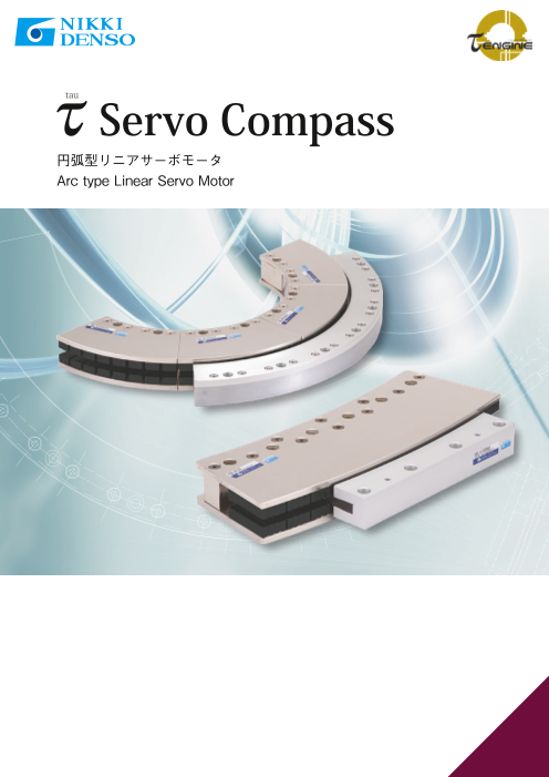


アライメントから旋回動作まで…。必要動作角度に応じた設置が可能な円弧型リニアモータ
円弧型リニアサーボモータ「τサーボコンパス」のご紹介
関連メディア
このカタログについて
| ドキュメント名 | 円弧型リニアサーボモータ τサーボコンパス |
|---|---|
| ドキュメント種別 | 製品カタログ |
| ファイルサイズ | 1.3Mb |
| 取り扱い企業 | CKD日機電装株式会社 (この企業の取り扱いカタログ一覧) |
この企業の関連カタログ

このカタログの内容
Page1
tau
Servo Compass
円弧型リニアサーボモータ
Arc type Linear Servo Motor
Page2
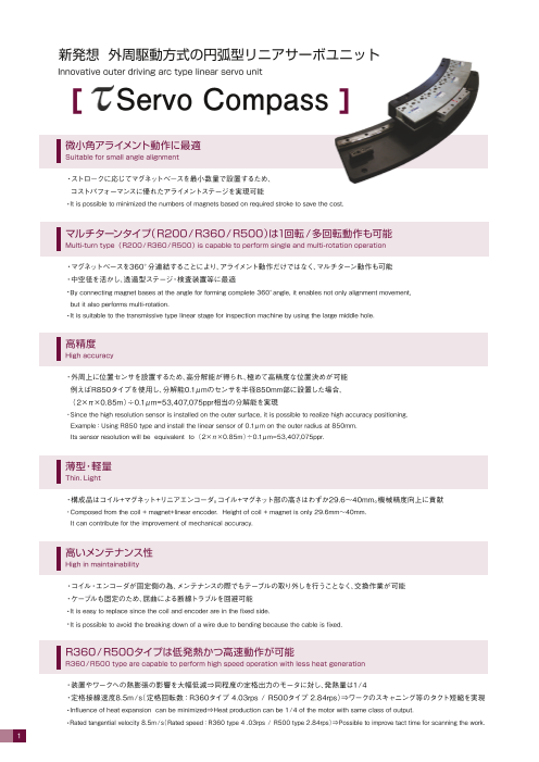
新発想 外周駆動方式の円弧型リニアサーボユニット
Innovative outer driving arc type linear servo unit
[ Servo Compass ]
微小角アライメント動作に最適
Suitable for small angle alignment
・ストロークに応じてマグネットベースを最小数量で設置するため、
コストパフォーマンスに優れたアライメントステージを実現可能
・It is possible to minimized the numbers of magnets based on required stroke to save the cost.
マルチターンタイプ(R200/R360/R500)は1回転/多回転動作も可能
Multi-turn type (R200/R360/R500) is capable to perform single and multi-rotation operation
・マグネットベースを360°分連結することにより、アライメント動作だけではなく、マルチターン動作も可能
・中空径を活かし、透過型ステージ・検査装置等に最適
・By connecting magnet bases at the angle for forming complete 360°angle, it enables not only alignment movement,
but it also performs multi-rotation.
・It is suitable to the transmissive type linear stage for inspection machine by using the large middle hole.
高精度
High accuracy
・外周上に位置センサを設置するため、高分解能が得られ、極めて高精度な位置決めが可能
例えばR850タイプを使用し、分解能0.1μmのセンサを半径850mm部に設置した場合、
(2×π×0.85m)÷0.1μm=53,407,075ppr相当の分解能を実現
・Since the high resolution sensor is installed on the outer surface, it is possible to realize high accuracy positioning.
Example:Using R850 type and install the linear sensor of 0.1μm on the outer radius at 850mm.
Its sensor resolution will be equivalent to (2×π×0.85m)÷0.1μm=53,407,075ppr.
薄型・軽量
Thin. Light
・構成品はコイル+マグネット+リニアエンコーダ。コイル+マグネット部の高さはわずか29.6~40mm。機械精度向上に貢献
・Composed from the coil + magnet+linear encoder. Height of coil + magnet is only 29.6mm~40mm.
It can contribute for the improvement of mechanical accuracy.
高いメンテナンス性
High in maintainability
・コイル・エンコーダが固定側の為、メンテナンスの際でもテーブルの取り外しを行うことなく、交換作業が可能
・ケーブルも固定のため、屈曲による断線トラブルを回避可能
・It is easy to replace since the coil and encoder are in the fixed side.
・It is possible to avoid the breaking down of a wire due to bending because the cable is fixed.
R360/R500タイプは低発熱かつ高速動作が可能
R360/R500 type are capable to perform high speed operation with less heat generation
・装置やワークへの熱膨張の影響を大幅低減⇒同程度の定格出力のモータに対し、発熱量は1/4
・定格接線速度8.5m/(s 定格回転数:R360タイプ 4.03rps / R500タイプ 2.84rps)⇒ワークのスキャニング等のタクト短縮を実現
・Influence of heat expansion can be minimized⇒Heat production can be 1/4 of the motor with same class of output.
・Rated tangential velocity 8.5m/(s Rated speed:R360 type 4 .03rps / R500 type 2.84rps)⇒Possible to improve tact time for scanning the work.
1
Page3
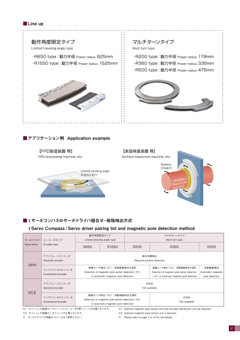
■Line up
動作角度限定タイプ マルチターンタイプ
Limited traveling angle type Multi turn type
・R850 type:動力半径 Power radius 825mm ・R200 type:動力半径 Power radius 178mm
・R1550 type:動力半径 Power radius 1525mm ・R360 type:動力半径 Power radius 335mm
・R500 type:動力半径 Power radius 475mm
■アプリケーション例 Application example
【FPD製造装置 等】 【表面検査装置 等】
FPD processing machine, etc. Surface inspection machine, etc.
Rotation
Limited traveling angle
Object t
o be
inspecte
d
■τサーボコンパス⇔サーボドライバ組合せ・磁極検出方式
τServo Compass/Servo driver pairing list and magnetic pole detection method
動作角度限定タイプ マルチターンタイプ
サーボドライバ エンコーダタイプ Limited traveling angle type Multi turn type
Servo driver Encoder type
R850 R1550 R200 R360 R500
アブソリュートエンコーダ 絶対位置検出
Absolute encoder Absolute position detection
VPH
磁極センサ検出(※1)/自動磁極検出を選択 磁極センサ検出(※2)/自動磁極検出を選択 自動磁極検出
インクリメンタルエンコーダ
Selection of magnetic pole sensor detection(※1) Selection of magnetic pole sensor detection Automatic magnetic
Incremental encoder
or automatic magnetic pole detection (※2) or automatic magnetic pole detection pole detection
アブソリュートエンコーダ 未対応
Absolute encoder Not available
VCⅡ
磁極センサ検出(※2)/自動磁極検出を選択
インクリメンタルエンコーダ 未対応
Selection of magnetic pole sensor detection(※2)
Incremental encoder Not available
or automatic magnetic pole detection
※1 オプションの磁極センサユニットとエンコーダ分配ユニットが必要となります。 ※1 Optional magnetic pole sensor unit and encoder distribution unit are required.
※2 オプションの磁極センサユニットが必要となります。 ※2 Optional magnetic pole sensor unit is required.
※ サーボドライバの詳細は、P.7~10をご参照ください。 ※ Please refer to page 7 to 10 for the details.
2
Page4
■共通仕様 Common specifications
温度 Temperature 0 ~ 40℃ 0 ~ 40℃
周囲条件
湿度 Humidity 85%以下(結露なきこと) 85% or less(No condensation allowed)
Ambient
conditions 腐食性ガス、研削油、金属粉、油等の有害な Do not install the motor in any harmful atmosphere
設置場所 Installetion area
雰囲気の中への設置はしないでください。 such as corrosive gas, cutting oil, metal dust, or oil
取付方向 Installation orientation 水平、垂直 Horizontal, vertical
推進方向 Driving direction 両方向 Both directions
冷却方法 Cooling method 自然空冷 Natural cooling
マグネットベース:白色 Magnet base:White
美装色 Finished color コイルユニット:白色(ユニット取付部分) Coil unit:White(unit mounting section)
黒色(樹脂部) black(plastic section)
絶縁階級 Insulation class F種 Class F
絶縁耐圧 Dielectric strength voltage 1500V(1分間) 1500V(for 1 minute)
耐振動 Vibration resistance 1G(3方向 各2h) 1G(for 2 hours in each of 3 directions)
耐衝撃 Impact resistance 5G(3方向 各3回) 5G(3 times for each of 3 directions)
保護等級 Protection class IP40(コイルユニット単体での等級) IP40(For the coil unit only)
■個別仕様 Specifications
◎動作角度限定タイプ Limited traveling angle type
モータタイプ Motor type R850 R1550
コイルユニット型式 Coil unit model CLV-CMC850A2B CLV-CME850A2B CLV-CME1550A2A
MBV-CMA850B MBV-CMA1550B
マグネットベース型式・有効角度 6.88° 3.68°
Magnet base model・effective angle MBV-CMB850B MBV-CMB1550B
10.32° 5.52°
定格接線推力 Rated tangential thrust ※1※2 N 150 300 300
最大接線推力 Maximum tangential thrust ※1※2 N 450 900 900
定格出力 Rated output W 450 900 900
動力半径 Power radius mm 825 825 1525
定格トルク Rated torque ※3 N・m 123 247 457
定格電流 Rated current A 2.85 5.7 5.7
定格接線速度 Rated tangential speed ※1 m/s 3 3 3
定格回転数 Rated speed ※3 rps 0.57 0.57 0.31
電源 Power supply AC200V 3φ 50/60Hz
組合せドライバ VPH Series NCR-H□ 2401□-A-□□0 2801□-A-□□0 2801□-A-□□0
Available driver ※4 VCⅡ Series NCR-□DA□ A2A-401D A2A-801D A2A-801D
◎マルチターンタイプ Multi turn type
モータタイプ Motor type R200 R360 R500
コイルユニット型式 Coil unit model CLD-CN53CA2A CLD-CM40HA2A CLD-CM40KA2A
マグネットベース型式・有効角度 MBD-CN14CA MBD-CM20HA MBD-CM20KA
Magnet base model・effective angle 45° 36° 24°
定格接線推力 Rated tangential thrust ※1※2 N 120 120 120
最大接線推力 Maximum tangential thrust ※1※2 N 360 360 360
定格出力 Rated output W 360 1020 1020
動力半径 Power radius mm 178 335 475
定格トルク Rated torque ※3 N・m 21.3 40 57
定格電流 Rated current A 2.8 4.5 4.5
定格接線速度 Rated tangential speed ※1 m/s 3 8.5 8.5
定格回転数 Rated speed ※3 rps 2.68 4.03 2.84
AC200V 3φ AC200V 1φ or 3φ AC200V 3φ
電源 Power supply
50/60Hz 50/60Hz 50/60Hz
組合せドライバ VPH Series NCR-H□ 2401□-A-□□0 2801□-A-□□0 2801□-A-□□0
Available driver ※4 VCⅡ Series NCR-□DA□ A2A-401D - -
※1 動力半径における値となります。 ※1 The value based on moving radius.
※2 複数のコイルユニットを使用することで推力アップが可能となります。 ※2 The force can be increased by using multi number of coil.
※3 接線推力、接線速度、動作半径をもとに換算した値となります。 ※3 The valued calculated based on the tangent line thrust, tangent line speed, and moving radius.
※4 磁極検出方式の詳細は、P.2「τサーボコンパス⇔サーボドライバ組合せ・磁極検出方式」を ※4 Please refer to P.2 "τServo Compass/Servo driver pairing list and magnetic pole detection method"
ご参照ください。 for details of the magnetic pole detection method.
※ 上記仕様は周囲温度25℃で、下記ヒートシンク(アルミ板)に取付け、動作した際の値です。
The specification values listed above are measured at an ambient temperature of 25℃ when the τServo compass mounted on the following heatsink (aluminum plate) operates.
適用コイルユニット Applicable coil unit ヒートシンクサイズ Heatsink size
CLV-CMC850A2B 250×250×15mm
CLV-CME850A2B、CLV-CME1550A2A、CLD-CN53CA2A 450×450×15mm
CLD-CM40HA2A、CLD-CM40KA2A 480×120×136mm
3
Page5
■ストローク角の算出 Calculation of stroke angle
ストローク角=マグネットベース総角度-コイルユニット角度-磁極センサ必要角度
Stroke angle=(total angle of magnet base)-(angle of coil unit)-(angle required for hall sensor)
■外形図 Dimensions
◎R850 type
※コイルユニットの取付面として、反対側を使用することも可能です。その際にはお問い合わせください。
The back side can be used as the mounting surface of coil unit. Please contact us if you intend to do so.
L CL A B T T1 N1 質量 Mass
型式 Model
mm mm mm mm deg deg 個 pcs kg
MBV-CMA850B 102.07 - - - - - - 2.3
マグネットベース Magnet base
MBV-CMB850B 152.64 - - - - - - 3.5
CLV-CMC850A2B - 200 10 180 13.4 14.4 4 0.8
コイルユニット Coil unit
CLV-CME850A2B - 388 44 300 26.2 27.2 6 1.7
◎R1550 type
L 質量 Mass
型式 Model
mm kg
MBV-CMA1550B 99.51 2.29
マグネットベース Magnet base ※コイルユニットの取付面として、反対側を使用することも可能です。その際にはお問い合わせください。
MBV-CMB1550B 149.23 3.44 The back side can be used as the mounting surface of coil unit.
コイルユニット Coil unit CLV-CME1550A2A - 1.63 Please contact us if you intend to do so.
4
Page6
■外形図 Dimensions
◎R200 type
※マグネットベースの取り付け部:R125+0.1/+0、コイルユニットの取り付け部:R238±0.1で取り付けてください。
Installation area of magnet base: R125+0.1/+0 Installation area of coil unit: R238±0.1
質量 Mass
型式 Model
kg
マグネットベース Magnet base MBD-CN14CA 2.06
コイルユニット Coil unit CLD-CN53CA2A 2
◎R360 type
① ②
① ②
②
①
質量 Mass
型式 Model
kg
マグネットベース Magnet base MBD-CM20HA 2.5
コイルユニット Coil unit CLD-CM40HA2A 1.9
5
Page7
■外形図 Dimensions
◎R500 type
① ②
① ②
②
①
質量 Mass
型式 Model
kg
マグネットベース Magnet base MBD-CM20KA 1.95
コイルユニット Coil unit CLD-CM40KA2A 2.4
■組合せセンサに関しての注意点 Caution in regards of pairing sensors
◎センサ分解能、スケール貼り付け半径の注意点 Important point for scale resolution and scale mounting radius
リニアスケールは、各サーボコンパスの公称半径の値以上の位置で、且つ下記の算出式から求められる
スケール外周半径の値を超えない位置に貼り付けてください。
Linear scale must be mounted in the value larger than the nominal radius and within the position of scale outer circumference radius
which can be calculated the formula in the below.
スケール外周半径 R ≦ 2,147,483,647 ×分解能(mm)/ 2π×(360/θM)
Scale outer circumference radius R ≦ 2,147,483,647 × Resolution(mm)/ 2π×(360/θM)
モータタイプ Motor type R850 R1550 R200 R360 R500
θM 1.72° 0.92° 11.25° 7.2° 4.8°
公称半径 Nominal radius 850 1550 200 360 500
分解能は、必ず0.5μm以下のものをご使用ください。
Resolution must be 0.5μm or lower for the usage.
◎角度分解能に関して About angular resolution
サーボコンパスの角度分解能は、円弧状に貼り付けたスケールテープの外周半径と、センサ分解能によって決まります。
Angular resolution of servo compass can be determined by the scale tape mounted on the outer circumference in an arc and the sensor resolution.
例) スケール外周半径:850.2mm、センサ分解能:0.1μmの場合
Example) In case of scale outer circumference radius : 850.2mm and Sensor resolution : 0.1μm
角度分解能 = 360〔°〕/(850.2〔mm〕× 2π/0.0001〔mm〕)
Angular resolution = 6.74 × 10-〔6 °/pulse〕 = 0.024〔arcsec/pulse〕
6
Page8
Servo driver
[ VPH Series ]
■Line up
◎ VPH-HA type I /O仕様 速度指令運転、トルク指令運転、パルス列指令運転、内蔵指令運転
I /O specification Speed command, torque command, pulse train command, and built-in command run modes
◎ VPH-HB type SSCNETⅢ/H仕様 SSCNETⅢ/H、SSCNETⅢに対応
SSCNETⅢ/H specification 速度指令運転、トルク指令運転、位置制御運転
Corresponding to SSCNETⅢ/H, SSCNETⅢ
Speed command operation, torque command operation, and position control operation
◎ VPH-HC type CC-Link仕様 CC-Lin(k Ver.1.10)通信に対応
CC-Link specification 速度指令運転、トルク指令運転、パルス列指令運転、内蔵指令運転
Corresponding to CC-Lin(k Ver.1.10) communication
Speed command operation, torque command operation, pulse train command,
and built-in command run modes
◎ VPH-HD type EtherCAT仕様 EtherCAT通信に対応(CiA402ドライブプロファイル対応)
EtherCAT specification 速度指令運転、トルク指令運転、位置制御運転
Corresponding to EtherCAT communication(corresponding to CiA402 drive profile)
Speed command operation, torque command operation, and position control operation
◎ VPH-HE type MECHATROLINK-Ⅲ仕様 MECHATROLINK-Ⅲ通信に対応
MECHATROLINK-Ⅲ specification 速度指令運転、トルク指令運転、位置制御運転
Corresponding to MECHATROLINK-Ⅲ communication
Speed command operation, torque command operation, and position control operation
■特長 Characteristics
滑らかな動作で位置決め時間を短縮 停止時の安定性を向上
Shortening the positioning speed with smooth operation Improvement in stability during stop
・2段S字加減速制御機能 ・停止中フィルタ機能。停止中のトルク精度の向上
Waveform of the two-stage s-curve acceleration and Filter function during stop. Improvement in torque
deceleration control function accuracy during stop
・フィードフォワード(FF)指令の精度向上 ・低速ゲイン切替機能の充実
Improve the accuracy of feed forward (FF) command Enhanced the low speed gain switching function
・フィードフォワード(FF)指令へのフィルタ機能
Filtering function to the feed forward (FF) command
速度安定性能がさらに向上 大イナーシャ負荷でも簡単にチューニングが可能
Further improvement in speed stability function Even if the load inertia is large, it is easy to tune
・トルクリップルを大幅抑制 ・フィードバックフィルタ自動設定機能
Significant reduction of torque ripple Feedback filter automatic setting function
■規格対応 Approved standards
(VPH-HCタイプは未対応)
(VPH-HC type is unsupported)
7
Page9
■共通仕様 Common specifications
使用時:0~55℃ At usage:0~55℃
温度 Temperature
保存時:-20~65℃ At storage:-20~65℃
At usage / storage:90% or less
周囲条件 湿度 Humidity 使用/保存時:90%以下 結露なきこと
(no condensation allowed)
Ambient
condition 腐食性ガス、研削油、金属粉、油等の有害な Do not install in harmful atmosphere such as
設置場所 Installation location 雰囲気中でないこと corrosive gas, grinding oil, metal dust, oil, etc.
直射日光の当たらない屋内であること Indoor place not exposed to direct sunlight
標高 Sea level 1000m以下 1000m or lower
耐振動 Vibration resistance 5.9m/s(2 10~55Hz) ただし共振なきこと 5.9m/s(2 10~55Hz) No resonance
駆動方式 Drive method 3相正弦波PWM 3-phase sine wave PWM
Regenerative brake:
制動方式 Control method 回生制動:回生抵抗外付け ※1
External regenerative resistor ※1
取付方式 Mounting type パネル取付 Panel mounting
速度制御範囲 ※3 1:5000 1:5000
Speed control range ※3 アナログ速度指令時 1:2000 ※4 Analog speed command 1:2000 ※4
性能 ※2 速度制御 負荷特性 Load 0~100%負荷時:±0.01%以下(定格速度にて) 0~100% load:±0.01% or les(s at rated speed)
速度変動率
Performance Speed control 電圧特性 Voltage 定格電圧±10%:0%(定格速度にて) Rated voltage ±10%:0%(at rated speed)
Speed
※2
variation 0~40℃:±0.1%以下(定格速度にて) 0~40℃:±0.1% or les(s at rated speed)
温度特性 Temperature
アナログ速度指令時 ±0.2%以下 ※4 Analog speed command:±0.2% or less ※4
トルク制御 分解能 Resolution 1:1000(定格トルクまで) 1:1000(Up to rated torque)
Torque control 再現性 Reproducibility ±1%(定格トルクまで) ±1%(Up to rated torque)
※1 回生抵抗器はオプションとなります。 ※1 Regenerative resistor is option.
※2 性能はサーボドライバ単体の値となります。 ※2 The performance is the value of the servo driver alone.
モータとの組み合わせにより性能を満たせない場合があります。 Performance may not be satisfied depending on the combination with the motor.
※3 100%負荷においてモータが停止しないことを条件としています。 ※3 When the load is 100%, the motor will be not stopped within the speed control range.
※4 VPH-HAタイプ(I/O仕様)のみ適用となります。 ※4 Only VPH-HA( I /O type) is applicable.
■個別仕様 Specifications
型式 Model NCR-H□ 2401□-A-□□0 2801□-A-□□0
定格出力 Rated output W 400 800
定格電圧 Rated voltage V AC200~240 1φ or 3φ
周波数 Frequency Hz 50/60
主回路入力電源 許容電圧変動 Permissible voltage fluctuation V AC170~264 AC170~264
Main circuit 5.5(1φ) 9.0(1φ)
input power supply 入力定格電流 Input rated current Arms
3.2(3φ) 5.2(3φ)
定格容量 Rated capacity kVA 1.1 1.8
突入電流 ※1 Inrush current ※1 A 45【5ms】 45【9ms】
定格電圧 Rated voltage V AC200~240 1φ
周波数 Frequency Hz 50/60
制御回路入力電源 許容電圧変動 Permissible voltage fluctuation V AC170~264 AC170~264
Control circuit
input power supply 入力定格電流 Input rated current Arms 0.12 0.12
消費電力 Power consumption W 15 15
突入電流 ※1 Inrush current ※1 A 17【3ms】 17【3ms】
連続出力電流 Continuous output current Arms 3.5 6.8
瞬時出力電流 Instant output current Arms 9.9 17.0
自然冷却(IP20) 強制冷却(IP20)
構造(保護等級) Structure(IP code)
Air cooling, open(IP20) Forced air cooling(IP20)
質量 Mass kg 約1.0 約1.5
※1 定格電圧AC240Vにおける値です。また、【 】内の数字は突入電流の時定数となります。 ※1 This is the value at the rated voltage of AC240V.Approximate time of inrush current to be stored is indicated in 【 】.
突入電流が収まるまでの時間は【 】内の数字の3倍を目安にしてください。 For the time of inrush current to be converged should be 3 times of the value indicated in 【 】.
■外形図 Dimensions
◎NCR-H□2401□-A-□□0 A矢視図(背面) ◎NCR-H□2801□-A-□□0 A矢視図(背面)
View A(Back view) View A(Back view)
50
(38) 160 (38) 70
160
30 50
←A矢視 ←A矢視
←View A ←View A
6
6 7
8
160
152
4
160
152
4
Page10
Servo driver / Controller
[ VCⅡ Series ]
■Line up
◎ VCⅡ-D type ドライバ仕様 速度指令運転、トルク指令運転、パルス列指令運転、内蔵指令運転
Driver type Speed command run, torque command run, pulse train command run, inner command run.
◎ VCⅡ-C1 type コントローラ仕様 位置決め、速度制御、トルク制御等プログラムによる自動運転が可能
Controller type Positioning, speed control, torque control by program are possible.
◎ VCⅡ-C6 type 自由曲線制御仕様 同期又は単独での自在な曲線動作が可能
Free curve controller type SIN波動作を簡単に実現
Operating curve can be done by either single or the multi axes synchronization.
Sine wave function can be easily realized.
◎ VCⅡ-D7 type SSCNETⅢ/H仕様 SSCNETⅢ/H、SSCNETⅢに対応
SSCNETⅢ/H type 速度指令運転、トルク指令運転、位置制御運転
SSCNETⅢ/H, SSCNETⅢ are supported.
Speed command run, torque command run, positioning control run.
★オプションI/F搭載で、MECHATROLINK-Ⅲ、CC-Linkにも接続可能
★By adding optimal I /F, it can connect to MECHATROLINK-Ⅲ or CC-Link.
■規格対応 Approved standards
(VCⅡ-D7タイプは未対応)
(VCⅡ-D7 type is unsupported)
■共通仕様 Common specifications
使用時:0~55℃(UL規格適合時は0~50℃) At usage:0~55℃(0~50℃ when it is certified with UL )
温度 Temperature
保存時:-20~60℃ At storage:-20~60℃
At usage / storage:85% or less, no condensing
周囲条件 湿度 Humidity 使用/保存時:85%以下 結露なきこと
(no condensation allowed)
Ambient
condition 腐食性ガス、研削油、金属粉、油等の Do not install in harmful atmosphere such as corrosive gas,
設置場所 Installation location 有害な雰囲気中でないこと grinding oil, metal dust, oil, etc.
直射日光の当たらない屋内であること Indoor place not exposed to direct sunlight
標高 Sea level 1000m以下 1000m or lower
耐振動 Vibration resistance 4.9m/s(2 10~50Hz) ただし共振なきこと 4.9m/s(2 10~50Hz) No resonance
駆動方式 Drive method 3相正弦波PWM 3-phase sine wave PWM
Regenerative brake:
制動方式 Control method 回生制動:回生抵抗外付け ※1
External regenerative resistor ※1
取付方式 Mounting type パネル取付 Panel mounting
性能 速度制御範囲 ※2
1:5000 1:5000
Performance Speed control range ※2
※1 回生抵抗器 装置定格出力400W:オプション/800W:標準付属
※2 100%負荷においてモータが停止しないことを条件としています。
※1 Regenerative resistor devise rated output 400W:option / 800W: standard accessories.
※2 When the load is 100%, the motor will be not stopped within the speed control range.
9
Page11
■個別仕様 Specifications
型式 Model NCR-□DA□ A2A-401J A2A-801J
定格出力 Rated output W 400 800
定格電圧 Rated voltage V AC200~230 3φ
周波数 Frequency Hz 50/60
主回路入力電源 許容電圧変動 Permissible voltage fluctuation V AC180~242
Main circuit
input power supply 入力定格電流 Input rated current Arms 3.2 5.2
定格容量 Rated capacity kVA 1.1 1.8
突入電流 ※1 Inrush current ※1 A 64【4ms】 64【4ms】
定格電圧 Rated voltage V AC200~230 1φ
周波数 Frequency Hz 50/60
制御回路入力電源 許容電圧変動 Permissible voltage fluctuation V AC180~242
Control circuit
input power supply 入力定格電流 Input rated current Arms 0.1 0.1
消費電力 Power consumption W 13 13
突入電流 ※1 Inrush current ※1 A 34【2ms】 34【2ms】
連続出力電流 Continuous output current Arms 3.4 5.0(6.8) ※2
瞬時出力電流 Instant output current Arms 9.9 17.0
構造(保護等級) Structure(IP code) 自然冷却(IP00) Air cooling, open( IP00)
質量 Mass kg 1.4 2.4
※1 【 】内は突入電流が収まるまでの時間の目安です。
※2 ( )内はUL規格を適合させない場合の値となります。
※3 使用環境によっては突入電流により、DC24V電源の過電流保護が働く可能性がありますので、定格容量の2倍以上の電源を推奨します。
※1 Approximate time of inrush current to be stored is indicated in 【 】.
※2 The value of non-certified UL model is indicated in ( ).
※3 It is recommended to have a power supply with 2 times larger capacity of rated allowable capacity since the over current protection function of DC24V
power supply may be occurred by inrush current duce to the operating environment.
■外形図 Dimensions
◎NCR-□DA□A2A-401D ◎NCR-□DA□A2A-801D
65 ※1
95 ※1
2 4 24
(36) 151
(9.5) 10 31 10
(36) 160
(9.5)
5.5
89(86) ※2 119(114) ※2
※1 VCⅡシリーズ本体のサイズとなります。また、VCⅡ-D7タイプ(SSCNETⅢ/H仕様)も同サイズとなります。
※2 VCⅡシリーズにオプションのCC-Link、MECHATROLINK-Ⅲ I /F装着時及びVCⅡ-D7用制御入出力ユニット装着時のサイズとなります。( )内は制御入出力拡張ユニット装着時。
※1 It is main body size of VCⅡseries. It is same size as VCⅡ-D7 type (SSENETⅢ/H).
※2 This is the size when Optional CC-Link or MECHATROLINK-Ⅲ I /F is mounted. It is also the size when control input /output unit is mounted on VCⅡ-D7.
Inside of ( ) is adapted when control input and output extension unit is equipped.
10
160 15
180 5
190
160 15
180 5
190
Page12
◎海外営業部
韓国独占販売店
●τDISC、τリニア、サーボコンパス、τENGINE はCKD日機電装株式会社の登録商標です。●SSCNETⅢ/H、SSCNETⅢ、CC-Linkは三菱電機株式会社の登録商標です。●EtherCAT®は、ドイツBeckhoff
Automation GmbHによりライセンスされた特許取得済み技術であり登録商標です。●MECHATROLINKはMECHATROLINK協会の登録商標です。●本製品の最終使用者が軍事関係であったり、用途が兵器などの製
造用である場合には「、外国為替及び外国貿易法」の定める輸出規制の対象となることがありますので、輸出される際には十分な審査及び必要な輸出手続きをお取りください。●このカタログの記載内容は2022年6月現在
のものです。●製品改良のため、予告なしに定格、仕様、寸法などの一部を変更する場合があります。予めご了承ください。●カタログ制作には、最善且つ慎重を期しておりますが、誤字、脱字などにより生じた損害については、
責任を負いかねますので、予めご了承ください。
Website
Overseas sales dept. Reprint without permission is forbidden
1-4-2, Osaku, Sakura-shi, Chiba, 285-0802, Japan TEL:+81-43-498-2315 FAX:+81-43-498-4654
E-mail:overseas@nikkidenso.co.jp
Head office
2-8-24, Arima, Miyamae-ku, Kawasaki-shi, Kanagawa, 216-0003, Japan TEL:+81-44-855-4311 FAX:+81-44-856-4831
Korean Exclusive Distributor
D311,Centroad,323 Incheon Tower-Daero, Yeonsu-Gu, Incheon, 22007, Korea TEL:+82-32-831-2133,2155 FAX:+82-32-831-2166
●"τDISC" , "τLinear" , "Servo compass", and "τENGINE" are the registered brand of CKD Nikki Denso Co., Ltd.●SSCNETⅢ/H, SSCNETⅢ, and CC-Link are the registered trademark of
Mitsubishi Electric.●EtherCAT® is the trademark and the patented technology licensed from EtherCATGmbH.●MECHATROLINK is the trademark of MECHATROLINK MEMBERS
ASSOCIATION.●Please make sure to have sufficient preliminary review and necessary export procedure. If the end user of this product is considered as militarily related for the
purpose of manufacturing the weapons, it will be the subject of export controls ruled by Foreign Exchange and Foreign Trade Control Law.●The contents in this catalog is as of June
2022.
Document No. N012G202102-a