


Lead-free 10x32mm Fuse 526 Series
このカタログについて
| ドキュメント名 | 526 Series High Current & Voltage Cartridge Fuses |
|---|---|
| ドキュメント種別 | 製品カタログ |
| ファイルサイズ | 660.6Kb |
| 取り扱い企業 | マウザー・エレクトロニクス (この企業の取り扱いカタログ一覧) |
この企業の関連カタログ


このカタログの内容
Page1
Fuse Datasheet
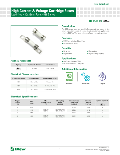
High Current & Voltage Cartridge Fuses
Lead-free > 10x32mm Fuse > 526 Series
RoHS Pb
Description
The 526 series fuses are specifically designed and tested to the
circuit protection needs of compact auto-electronics applications,
which is 500 Vdc/Vac rated with remarkable interrupting rating.
Features
■ RoHS compliant and Lead-free
■ High Interrupt Rating
Benefits
■ Small size ■ High voltage
■ High current ■ High breaking capacity
Applications
Agency Approvals ■ On-Board Charger (OBC)
■ Power Distribution Unit (PDU)
Agency Agency File Number Ampere Range
E10480 30 A to 60 A Additional Information
Electrical Characteristics
% of Ampere Rating Ampere Rating Opening Time at 25ºC
100% 30 A to 60 A 4 hours, Min.
Resources Accessories Samples
135% 30 A to 60 A 60 minutes, Max.
200% 30 A to 60 A 120 seconds, Max.
Electrical Specifications
Ampere Max Interrupting Nominal Code Nominal Agency Approvals
Amp
Rating Voltage Rating Rating Resistance Melting
Code
(A) (V) (AC/DC) (mOhm) I2t (A2sec)
30 030. 0.0028 1070 x
500VDC 10KA@500VDC
40 040. 500VAC 10KA@500VAC 0.0020 2340 x
50 050. 0.0014 3850 x
60 060. 500VDC 10KA@500VDC
300VAC 10KA@300VAC 0.0011 6290 x
© 2022 Littelfuse, Inc.
1 Specifications are subject to change without notice.
Revised: BA.02/01/22
Page2
Fuse Datasheet
High Current & Voltage Cartridge Fuses
Lead-free > 10x32mm Fuse > 526 Series
Temperature Re-rating Curve Average Time Current Curves
120%
110% 10000
100%
90% 1000
80%
70%
60% 100
50%
40%
10
30%
20%
-55 -35 -15 5 25 45 65 85 105 125 1
Ambient Temperature (°C)
Note: 0.1
Rerating depicted in this curve is in addition to the standard derating of 25% for continuous operation.
0.01
0.001
10 100 1000 10000
Current in Amperes
Note:
For 50A, 60A rating, it may not break current consistently when overload current is less than 200%In
(represented by dotted portion of this time-current curve), as maybe arc current continuously pass-through fuse
Product Characteristics under this condition. Do not recommend to use conditions of below 200%In overload.
Body: Glass fiber Soldering Parameters–Wave Soldering
Materials Cap: Ni plated copper alloy
Terminal: Ni/Sn plated copper alloy
MIL-STD-202, Method 213,
Mechanical Shock Test Condition I
(100 G’s peak for 6 milliseconds)
Solderability Reference MIL-STD-202 method 208
Cap 1: Brand logo,
Product Marking current and voltage ratings
Cap 2: Agency approval marks
MIL-Std 202 Method 210
Resistance to Solder Heat Test Condition B
(10 sec at 260 °C)
Operating Temperature -55 °C to +125 °C Wave Parameter Lead-Free Recommendation
Preheat:
(Depends on Flex Activation
Thermal Shock MIL-STD-202G, Method 107G, (Typical Industry Recommendation)
Test condition B Temperature)
Temperature Minimum 100 ºC
Vibration MIL-STD-202G, Method 201A Temperature Maximum 150 ºC
Preheat Time 60–180 seconds
Moisture Resistance MIL-STD-202G, Method 103B,
Test condition A Solder Pot Temperature 260 ºC Maximum
Solder Dwell Time 2–5 seconds
MIL-STD-202G, Method 101E,
Salt Spray Recommended Hand-Solder Parameters:
Test condition B Solder Iron Temperature: 350 ºC +/- 5 ºC
Heating Time: 5 seconds max.
Note: These devices are not recommended for IR or Convection Reflow process.
© 2022 Littelfuse, Inc.
2 Specifications are subject to change without notice.
Revised: BA.02/01/22
Percent of Rating
Time in seconds
30A
40A
50A
60A
Page3
Fuse Datasheet
High Current & Voltage Cartridge Fuses
Lead-free > 10x32mm Fuse > 526 Series
Dimensions
- Through hole terminal - Bolt down terminal
Recommended PCB layout
Unit: mm
Part Numbering System
0526 xxxx U X TH P
Series P: Lead-Free
Amp Code Option Code
Refer to Amp Code TH: Through hole type terminal
column of Electrical ISO: Bolt Down Terminal
Characteristics Table
Quantity Code Packaging Code
U=500 X= Filler
Z=400
Packaging
Packaging Option Packaging Specification Quantity Quantity & Packaging Code Reel Size
526 Through hole terminal
Tray NA 500 NA NA
526 Bolt down terminal
Tray NA 400 NA NA
Disclaimer Notice - Information furnished is believed to be accurate and reliable. However, users should independently evaluate the suitability of and test each product selected for their own applications. Littelfuse products are
not designed for, and may not be used in, all applications. Read complete Disclaimer Notice at http://www.littelfuse.com/disclaimer-electronics.
© 2022 Littelfuse, Inc.
3 Specifications are subject to change without notice.
Revised: BA.02/01/22