


C4AK, Radial, 2 Leads, 700 – 900 VDC, for DC Link
(Automotive Grade) - 125°C with Long Life and High Voltage
このカタログについて
| ドキュメント名 | Printed Circuit Board Mount Power Film Capacitors |
|---|---|
| ドキュメント種別 | 製品カタログ |
| ファイルサイズ | 978.3Kb |
| 取り扱い企業 | マウザー・エレクトロニクス (この企業の取り扱いカタログ一覧) |
この企業の関連カタログ


このカタログの内容
Page1
Overview、Applications、Benefits、Part Number System
Printed Circuit Board Mount Power Film Capacitors
C4AK, Radial, 2 Leads, 700 – 900 VDC, for DC Link
(Automotive Grade) - 125°C with Long Life and High Voltage
Overview Applications
The C4AK capacitor is a new polypropylene material Typical applications include DC filtering, DC link, power
metallized film capacitor with a rectangular, plastic box- electronics, energy storage, renewable energy grid interface,
type design (black color) filled with resin, and uses 2 tinned motor drives, and automotive applications.
wires.
Automotive grade devices meet the demanding Automotive
Electronics Council's AEC-Q200 qualification requirements
with longer life at 125°C (higher voltage derated) and 135°C.
Benefits
• High voltage & long life at 125°C
• Voltage derated at 135°C
• THB 85°C/85% R.H. at VR for 1,000 hours
• Low Halogen Content according to JS709C
• Self-healing
• Low loss
• Low ESL
• Low profile dimensions available under request
• High ripple current
• High dV/dt
• High capacitance density
• High contact reliability
• Suitable for high frequency applications
• Automotive Grades (AEC-Q200)
Part Number System
C4 A K J B W 5125 A 3 2 J
Rated
Series Type Application Voltage Case Terminals Capacitance Lead
Release Diameter Size Code: Tolerance
(VDC) Code Code (pF) (mm) B x H x L (mm)
C4 = A = K = DC link J = 700 B = Box plastic U = 2 pins Digits 2 – 4 A = 3 = 1.2 See dimensions J = 5%
MKP Box, wire Automotive O = 900 case W = 4 pins indicate the first Standard table below K = 10%
power terminals Grade with L = Low Profile three digits of for valid case
capacitors new PP resin box, plastic case the capacitance sizes
material value. First digit
indicates the
number of zeros
to be added.
Built Into Tomorrow
© KEMET Electronics Corporation • KEMET Tower • One East Broward Boulevard F3129_C4AK • 8/30/2021 1
Fort Lauderdale, FL 33301 USA • 954-766-2800 • www.kemet.com
Page2
Series Selection
Power and AC Film Capacitors – Printed Circuit Board Mount Power Film Capacitors
C4AK, Radial, 2 Leads, 700 – 900 VDC, for DC Link (Automotive Grade) - 125°C with Long Life and High Voltage
Series Selection
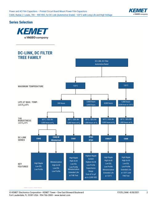
DC-LINK, DC FILTER
TREE FAMILY
DC-LINK, DC Filter
Automotive Rated
MAXIMUM TEMPERATURE 125°C 135°C
LIFE AT MAX. TEMP. 2,000 hours 1,000 hours
200 hours 4,000 hours
|C/C0|≤5% 3,000 hours (4,000 hours at 125°C)
THB
ROBUSTNESS 60°C / 95% RH 85°C / 85% RH 85°C / 85% RH 60°C / 95% RH 85°C / 85% RH
|C/C0|≤5% 1,000 hours at VR 1,000 hours at VR 1,000 hours at VR 1,000 hours at VR 1,000 hours at VR
DC-LINK C4AQ-M R75H
C4AQ
SERIES C4AU C4AQ-P C4AK
Miniaturized R76H
Highest Ripple
High Ripple High Ripple High Ripple
Current
High dv/dt High dv/dt
High Ripple Miniaturization High dv/dt Highest dv/dt
KEY High dv/dt Low ESL Low ESL Low ESL
Low Profile
FEATURES Low ESL
Low ESL Low Profile Low Profile Low Profile
Low Profile Miniaturization Capacitance
Miniaturization Extended Life
Low Profile Extended Life Range
Extended Life at 135°C and
at THB Test from nF to µF
at 125°C THB Test
up to 2,000 VDC
©KEMET Corporation. All Rights Reserved.
© KEMET Electronics Corporation • KEMET Tower • One East Broward Boulevard F3129_C4AK • 8/30/2021 2
Fort Lauderdale, FL 33301 USA • 954-766-2800 • www.kemet.com
Page3
Dimensions – Millimeters
Power and AC Film Capacitors – Printed Circuit Board Mount Power Film Capacitors
C4AK, Radial, 2 Leads, 700 – 900 VDC, for DC Link (Automotive Grade) - 125°C with Long Life and High Voltage
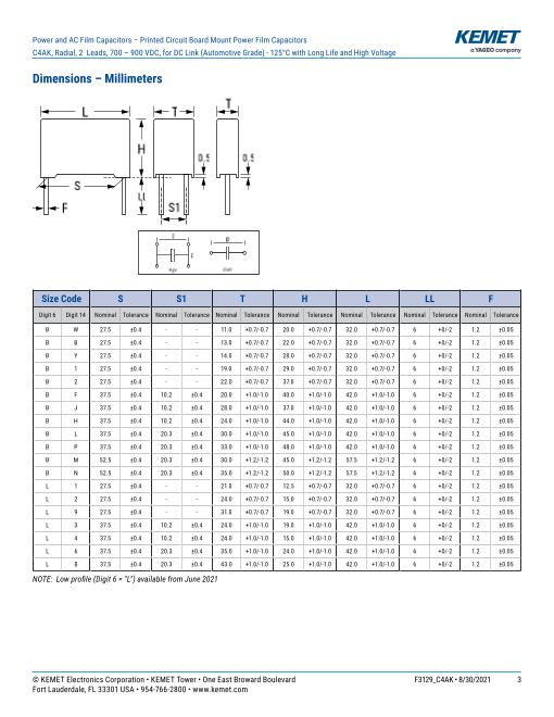
Dimensions – Millimeters
L T T
H
0.5 0.5
S
LL
F S1
p p
p1
4-pin 2-pin
Size Code S S1 T H L LL F
Digit 6 Digit 14 Nominal Tolerance Nominal Tolerance Nominal Tolerance Nominal Tolerance Nominal Tolerance Nominal Tolerance Nominal Tolerance
B W 27.5 ±0.4 - - 11.0 +0.7/-0.7 20.0 +0.7/-0.7 32.0 +0.7/-0.7 6 +0/-2 1.2 ±0.05
B B 27.5 ±0.4 - - 13.0 +0.7/-0.7 22.0 +0.7/-0.7 32.0 +0.7/-0.7 6 +0/-2 1.2 ±0.05
B Y 27.5 ±0.4 - - 14.0 +0.7/-0.7 28.0 +0.7/-0.7 32.0 +0.7/-0.7 6 +0/-2 1.2 ±0.05
B 1 27.5 ±0.4 - - 19.0 +0.7/-0.7 29.0 +0.7/-0.7 32.0 +0.7/-0.7 6 +0/-2 1.2 ±0.05
B 2 27.5 ±0.4 - - 22.0 +0.7/-0.7 37.0 +0.7/-0.7 32.0 +0.7/-0.7 6 +0/-2 1.2 ±0.05
B F 37.5 ±0.4 10.2 ±0.4 20.0 +1.0/-1.0 40.0 +1.0/-1.0 42.0 +1.0/-1.0 6 +0/-2 1.2 ±0.05
B J 37.5 ±0.4 10.2 ±0.4 28.0 +1.0/-1.0 37.0 +1.0/-1.0 42.0 +1.0/-1.0 6 +0/-2 1.2 ±0.05
B H 37.5 ±0.4 10.2 ±0.4 24.0 +1.0/-1.0 44.0 +1.0/-1.0 42.0 +1.0/-1.0 6 +0/-2 1.2 ±0.05
B L 37.5 ±0.4 20.3 ±0.4 30.0 +1.0/-1.0 45.0 +1.0/-1.0 42.0 +1.0/-1.0 6 +0/-2 1.2 ±0.05
B P 37.5 ±0.4 20.3 ±0.4 33.0 +1.0/-1.0 48.0 +1.0/-1.0 42.0 +1.0/-1.0 6 +0/-2 1.2 ±0.05
B M 52.5 ±0.4 20.3 ±0.4 30.0 +1.2/-1.2 45.0 +1.2/-1.2 57.5 +1.2/-1.2 6 +0/-2 1.2 ±0.05
B N 52.5 ±0.4 20.3 ±0.4 35.0 +1.2/-1.2 50.0 +1.2/-1.2 57.5 +1.2/-1.2 6 +0/-2 1.2 ±0.05
L 1 27.5 ±0.4 - - 21.0 +0.7/-0.7 12.5 +0.7/-0.7 32.0 +0.7/-0.7 6 +0/-2 1.2 ±0.05
L 2 27.5 ±0.4 - - 24.0 +0.7/-0.7 15.0 +0.7/-0.7 32.0 +0.7/-0.7 6 +0/-2 1.2 ±0.05
L 9 27.5 ±0.4 - - 31.0 +0.7/-0.7 19.0 +0.7/-0.7 32.0 +0.7/-0.7 6 +0/-2 1.2 ±0.05
L 3 37.5 ±0.4 10.2 ±0.4 24.0 +1.0/-1.0 19.0 +1.0/-1.0 42.0 +1.0/-1.0 6 +0/-2 1.2 ±0.05
L 4 37.5 ±0.4 10.2 ±0.4 24.0 +1.0/-1.0 15.0 +1.0/-1.0 42.0 +1.0/-1.0 6 +0/-2 1.2 ±0.05
L 6 37.5 ±0.4 20.3 ±0.4 35.0 +1.0/-1.0 24.0 +1.0/-1.0 42.0 +1.0/-1.0 6 +0/-2 1.2 ±0.05
L 8 37.5 ±0.4 20.3 ±0.4 43.0 +1.0/-1.0 25.0 +1.0/-1.0 42.0 +1.0/-1.0 6 +0/-2 1.2 ±0.05
NOTE: Low profile (Digit 6 = "L") available from June 2021
© KEMET Electronics Corporation • KEMET Tower • One East Broward Boulevard F3129_C4AK • 8/30/2021 3
Fort Lauderdale, FL 33301 USA • 954-766-2800 • www.kemet.com
Page4
Qualification、General Technical Data
Power and AC Film Capacitors – Printed Circuit Board Mount Power Film Capacitors
C4AK, Radial, 2 Leads, 700 – 900 VDC, for DC Link (Automotive Grade) - 125°C with Long Life and High Voltage
Qualification
Reference Standards IEC 61071, EN 61071, VDE0560
Climatic Category 55/105/56 according to IEC
60068-1
Automotive grade products meet or exceed the requirements outlined by the Automotive Electronics Council. Details regarding test methods and
conditions are referenced in document AEC-Q200, Stress Test Qualification for Passive Components. For additional information regarding the
Automotive Electronics Council and AEC-Q200, visit the AEC website at www.aecouncil.com.
General Technical Data
Dielectric Polypropylene metallized film, non-inductive type, self-healing property
Application DC filtering, DC link
Special Features AEC–Q200 qualified
Climatic Category 55/105/56 IEC 60068–1
Temperature Range −55°C to +135°C
Endurance Test 500 hours at 1.3 x VOP + C/D + 500 hours at 1.3 x VOP
at 85°C, 105°C, 125°C, 135°C
Standard IEC 61071, EN 61071, VDE0560, AEC–Q200
Protection Solvent resistant plastic case UL 94 V–0 compliant
Thermosetting resin sealing UL 94 V–0 compliant
Installation Any position
Leads Tinned wires, standard lead wire length 6 (+0/−2) mm
Packaging Packed in cardboard trays with protection for the terminals
Compliant with Directive 2002/95/EC and Directive 2011/65/EU of the
RoHS Compliance European Parliament and the Council of the EU on 8 June 2011, including
the Commission Delegated Directive (EU) 2015/863 that amended Annex
II to Directive 2011/65/EU.
© KEMET Electronics Corporation • KEMET Tower • One East Broward Boulevard F3129_C4AK • 8/30/2021 4
Fort Lauderdale, FL 33301 USA • 954-766-2800 • www.kemet.com
Page5
Electrical Characteristics、Life Expectancy
Power and AC Film Capacitors – Printed Circuit Board Mount Power Film Capacitors
C4AK, Radial, 2 Leads, 700 – 900 VDC, for DC Link (Automotive Grade) - 125°C with Long Life and High Voltage
Electrical Characteristics
Rated Capacitance Range 1.5 – 60 µF
Rated Voltage (VNDC) Range 700 – 900 VDC
Capacitance Tolerance ±5% (J) or ±10% (K) measured at T = +25°C ±5°C
Dissipation Factor PP Typical
(tgδ0) ≤ 0.0002 at 10 kHz with T = 25°C ±5°C
Surge Voltage 1.5 * VNDC for maximum 10 times in a lifetime at 25°C ±5°C
1.15 * VNDC for maximum 30 minutes, once per day
Overvoltage (IEC 61071)
1.3 * VNDC for maximum 1 minute, once per day
Peak Non-Repetitive Current 1.5 * IPKR for maximum 1,000 times in a lifetime
Insulation Resistance IR x C ≥ 30.000 seconds at 100 VDC 1 minute at T = +25°C ±5°C
Capacitance Deviation in
Operation ±2.0% maximum on capacitance value measured at T = +25°C ±5°C
Temperature Storage –40 to +80°C
Storage time ≤ 36 months from the date marked on the label glued to the package
Permissible Relative Annual average ≤ 70%, 85% on 30 days/year randomly distributed
Humidity - Storage throughout year. Dewing not admissible.
Life Expectancy
100,000 hours at VNDC at hot spot temperature THS = +85°C
Life Expectancy 20,000 hours at VOP105 at hot spot temperature THS = +105°C
1,000 hours at VOP135 at hot spot temperature THS = +135°C
Capacitance Drop at End of Life –5% (typical)
Failure Rate IEC 61709 ≤ 200 FIT at VOP85 at hot spot temperature THS = +85°C
© KEMET Electronics Corporation • KEMET Tower • One East Broward Boulevard F3129_C4AK • 8/30/2021 5
Fort Lauderdale, FL 33301 USA • 954-766-2800 • www.kemet.com
Page6
Test Method、Operative Voltage Derating
Power and AC Film Capacitors – Printed Circuit Board Mount Power Film Capacitors
C4AK, Radial, 2 Leads, 700 – 900 VDC, for DC Link (Automotive Grade) - 125°C with Long Life and High Voltage
Test Method
Test Voltage Between Terminals 1.5 * VNDC for 10 seconds or 1.65 * VNDC for 2 seconds,
at T = +25°C ±5°C
Test Voltage Between
Terminals and Case 3.2 k VAC 50 Hz for 2 seconds
Damp Heat IEC 60068-2-78
Change of Temperature IEC 60068-2-14
Biased Humidity Test 40°C/93% |ΔC/C0| ≤ 5%
R.H. at V - 1,000 hours |ΔDF/DF0| ≤ 100% (at 10 kHz)
NDC IR ≥ 50% of initial limit
Biased Humidity Test 60°C/95% |ΔC/C0| ≤ 5%
R.H. at V - 1,000 hours |ΔDF/DF0| ≤ 200% (at 10 kHz)
NDC IR ≥ 100 MΩ
Biased Humidity Test 85°C/85% |ΔC/C0| ≤ 10%
R.H. at VNDC - 1,000 hours |ΔDF| ≤ 0.005 (at 1 kHz)
IR ≥ 100 MΩ
Operative Voltage Derating
Symbol Voltage (VDC) Life Expectancy (Hours)
Rated Voltage at 85°C (THS) VNDC 700 900 100,000
Operating Voltage at 105°C (THS) VOP105 600 800 20,000
Operating Voltage at 125°C (THS) VOP125 500 720 4,000
Operating Voltage at 135°C (THS) VOP135 400 500 1,000
Maximum Overtemperature ∆Tlim vs TAMB Maximum Irms vs. TAMB
35 120%
30 100%
25
80%
20
60%
15
40%
10
5 20%
0 0%
Temperature TAMB(°C) TAMB (°C)
TAMB is the maximum ambient temperature surrounding the capacitor or hottest contact point (e.g. tracks), whichever is higher, in the worst operation
conditions in °C.
© KEMET Electronics Corporation • KEMET Tower • One East Broward Boulevard F3129_C4AK • 8/30/2021 6
Fort Lauderdale, FL 33301 USA • 954-766-2800 • www.kemet.com
∆Tlim (°C)
0
5
10
15
20
25
30
35
40
45
50
55
60
65
70
75
80
85
90
95
100
105
110
115
120
125
130
135
Maximum Irms
25
30
35
40
45
50
55
60
65
70
75
80
85
90
95
100
105
110
115
120
125
130
135
Page7
Typical Waveforms
Power and AC Film Capacitors – Printed Circuit Board Mount Power Film Capacitors
C4AK, Radial, 2 Leads, 700 – 900 VDC, for DC Link (Automotive Grade) - 125°C with Long Life and High Voltage
Typical Waveforms
V
VNDC / VPK+
VPK-
t
V
VNDC / VPK+
VPK-
t
V
VNDC / VPK+
VPK-
t
The applied peak-to-peak ripple voltage shall not exceed 0.2 x VNDC.
The peak voltage shall not exceed the rated voltage VNDC.
© KEMET Electronics Corporation • KEMET Tower • One East Broward Boulevard F3129_C4AK • 8/30/2021 7
Fort Lauderdale, FL 33301 USA • 954-766-2800 • www.kemet.com
Page8
Life Expectancy/Failure Quota Graphs、Environmental Compliance
Power and AC Film Capacitors – Printed Circuit Board Mount Power Film Capacitors
C4AK, Radial, 2 Leads, 700 – 900 VDC, for DC Link (Automotive Grade) - 125°C with Long Life and High Voltage
Life Expectancy/Failure Quota Graphs
Lifetime Curve at Hot Spot Temperature - 700VDC Lifetime Curve at Hot Spot Temperature - 900VDC
1000000 1000000
100000 100000
85
10000 85
10000
105 105
125 125
135 135
1000 1000
100 100
0.4 0.6 0.8 1 1.2 1.4 0.4 0.6 0.8 1 1.2 1.4
V/VNDC V/VNDC
C4AK FIT at Hot Spot Temperature
10,000
1,000 70
85
95
105
100
110
120
125
135
10
1
0.5 0.6 0.7 0.8 0.9 1.0 1.1 1.2 1.3 1.4
V/VNDC
Environmental Compliance
As a leading global supplier of electronic components and an environmentally conscious company, KEMET continually
aspires to improve the environmental effects of our manufacturing processes and our finished electronic components.
In Europe (RoHS Directive) and in some other geographical areas such as China (China RoHS), legislation has been enacted
to prevent or otherwise limit the use of certain hazardous materials, including lead (Pb), in electronic equipment. KEMET
monitors legislation globally to ensure compliance and endeavors to adjust our manufacturing processes and/or electronic
components as may be required by applicable law.
© KEMET Electronics Corporation • KEMET Tower • One East Broward Boulevard F3129_C4AK • 8/30/2021 8
Fort Lauderdale, FL 33301 USA • 954-766-2800 • www.kemet.com
FIT Lifetime expectancy [h]
Lifetime expectancy (h)
Page9
Materials & Environment、Dissipation Factor、Sealing
Power and AC Film Capacitors – Printed Circuit Board Mount Power Film Capacitors
C4AK, Radial, 2 Leads, 700 – 900 VDC, for DC Link (Automotive Grade) - 125°C with Long Life and High Voltage
Environmental Compliance cont.
For military, medical, automotive, and some commercial applications, the use of lead (Pb) in the termination is necessary
and/or required by design. KEMET is committed to communicating RoHS compliance to our customers. Information related
to RoHS compliance will be provided in data sheets and using specific identifiers on the packaging labels.
All KEMET power film capacitors are RoHS compliant.
LH
Low Halogen
All Part Numbers
Materials & Environment
The selection of raw materials that KEMET uses for the production of its electronic components is the result of extensive
experience. KEMET directs specific attention toward environmental protection. KEMET selects its suppliers according to
ISO 9001 standards and performs statistical analyses on raw materials before acceptance for use in manufacturing our
electronic components. All materials are, to the best of KEMET’s knowledge, non-toxic and free from cadmium; mercury;
chrome and compounds; polychlorine triphenyl (PCB); bromide and chlorinedioxins bromurate clorurate; CFC and HCFC;
and asbestos.
Dissipation Factor
Dissipation factor is a complex function involved with capacitor inefficiency. The tgδ may vary up and down with increased
temperature. For more information, refer to Performance Characteristics.
Sealing
Hermetically Sealed Capacitors
As the temperature increases, the pressure inside the capacitor increases. If the internal pressure is high enough, it can
cause a breach in the capacitor. Such a breach can result in leakage, impregnation, filling fluid, or moisture susceptibility.
Barometric Pressure
The altitude at which hermetically sealed capacitors are operated controls the capacitor's voltage rating. As the barometric
pressure decreases, the susceptibility to terminal arc-over increases. Non-hermetic capacitors can be affected by internal
stresses due to pressure changes. These effects can be in the form of capacitance changes, dielectric arc-over, and/or low
insulation resistance. Altitude can also affect heat transfer. Heat that is generated in an operation cannot be dissipated
properly, and high RI2 losses and eventual failure can result.
© KEMET Electronics Corporation • KEMET Tower • One East Broward Boulevard F3129_C4AK • 8/30/2021 9
Fort Lauderdale, FL 33301 USA • 954-766-2800 • www.kemet.com
Page10
Table 1 – Ratings & Part Number Reference
Power and AC Film Capacitors – Printed Circuit Board Mount Power Film Capacitors
C4AK, Radial, 2 Leads, 700 – 900 VDC, for DC Link (Automotive Grade) - 125°C with Long Life and High Voltage
Table 1 – Ratings & Part Number Reference
Cap Dimensions Irms*
dV/dt Ipkr ESL ESRtyp 95°C at Rth
Value VDC (mm) at 10 kHz (HS/Amb) Packaging PART
10 kHz
(µF) Quantity NUMBER
T H L S S1 V/µs Apk nH mΩ Arms (°C/W)
VNDC at 85°C = 700 VDC; VOP105 at 105°C = 600 VDC; VOP125 at 125°C = 500 VDC
1.8 700 11 20 32 27.5 \ 40 72 17 28.5 4.2 44 256 C4AKJBU4180A3WJ
2.7 700 13 22 32 27.5 \ 40 108 22 19.5 5.6 36 234 C4AKJBU4270A3BJ
4 700 14 28 32 27.5 \ 40 160 24 13.4 7.1 33 96 C4AKJBU4400A3YJ
8 700 19 29 32 27.5 \ 40 320 25 8.0 9.7 29 72 C4AKJBU4800A31J
12 700 22 37 32 27.5 \ 40 480 28 6.1 12.5 23 64 C4AKJBU5125A32J
15 700 20 40 42 37.5 10.2 20 300 12 6.8 12.7 20 58 C4AKJBW5150A3FJ
20 700 28 37 42 37.5 10.2 20 400 10 5.2 15.4 18 36 C4AKJBW5200A3JJ
22 700 24 44 42 37.5 10.2 20 440 12 4.7 16.6 17 44 C4AKJBW5220A3HJ
30 700 30 45 42 37.5 20.3 20 600 13 3.2 21.5 15 36 C4AKJBW5300A3LJ
35 700 33 48 42 37.5 20.3 20 700 14 3.0 23.0 14 30 C4AKJBW5350A3PJ
45 700 30 45 57.5 52.5 20.3 10 450 13 4.8 19.5 12 27 C4AKJBW5450A3MJ
60 700 35 50 57.5 52.5 20.3 10 600 15 3.7 24.5 10 23 C4AKJBW5600A3NJ
VNDC at 85°C = 900 VDC; VOP105 at 105°C = 800 VDC; VOP125 at 125°C = 720 VDC
1.2 900 11 20 32 27.5 \ 40 48 17 35.0 3.8 44 256 C4AKOBU4120A3WJ
1.5 900 13 22 32 27.5 \ 40 60 22 28.0 4.7 36 234 C4AKOBU4150A3BJ
2.7 900 14 28 32 27.5 \ 40 108 24 16.0 6.5 33 96 C4AKOBU4270A3YJ
3.3 900 14 28 32 27.5 \ 40 132 24 14.2 6.8 33 96 C4AKOBU4330A3YJ
5 900 19 29 32 27.5 \ 40 200 25 10.0 8.7 29 72 C4AKOBU4500A31J
8 900 22 37 32 27.5 \ 40 320 28 7.3 11.5 23 64 C4AKOBU4800A32J
10 900 20 40 42 37.5 10.2 20 200 12 8.2 11.7 20 58 C4AKOBW5100A3FJ
14 900 28 37 42 37.5 10.2 20 280 10 5.9 14.4 18 36 C4AKOBW5140A3JJ
15 900 24 44 42 37.5 10.2 20 300 12 5.6 15.3 17 44 C4AKOBW5150A3HJ
20 900 30 45 42 37.5 20.3 20 400 13 4.3 18.5 15 36 C4AKOBW5200A3LJ
24 900 33 48 42 37.5 20.3 20 480 14 3.5 21.5 14 30 C4AKOBW5240A3PK
30 900 30 45 57.5 52.5 20.3 10 300 13 5.7 18.0 12 27 C4AKOBW5300A3MJ
40 900 35 50 57.5 52.5 20.3 10 400 15 4.4 22.5 10 23 C4AKOBW5400A3NK
T H L S S1 V/µs Apk nH mΩ Arms (°C/W)
Cap
Value VDC ESR Irms* Packaging PART
Dimensions (mm) dV/dt lpkr ESL typ Rth
(µF) Quantity NUMBER
at 10 kHz 95°C at
10 kHz (HS/Amb)
(*) Irms value that leads to a ΔT of ≈ 30°C in the hot spot » THS = TAMB + ΔT = 95°C + 30°C = 125°C. Attention: Hot spot at 125°C reduced the life time!
© KEMET Electronics Corporation • KEMET Tower • One East Broward Boulevard F3129_C4AK • 8/30/2021 10
Fort Lauderdale, FL 33301 USA • 954-766-2800 • www.kemet.com
Page11
Table 2 – Ratings & Part Number Reference for Low Profile Design
Power and AC Film Capacitors – Printed Circuit Board Mount Power Film Capacitors
C4AK, Radial, 2 Leads, 700 – 900 VDC, for DC Link (Automotive Grade) - 125°C with Long Life and High Voltage
Table 2 – Ratings & Part Number Reference for Low Profile Design
Cap Dimensions dV/dt Ipkr ESL ESR Irms*
typ
(mm) at 10 kHz 95°C at Rth
Value VDC 10 kHz (HS/Amb) Packaging PART
(µF) Quantity NUMBER
T H L S S1 V/µs Apk nH mΩ Arms (°C/W)
VNDC at 85°C = 700 VDC; VOP105 at 105°C = 600 VDC; VOP125 at 125°C = 500 VDC
2.7 700 21 12.5 32 27.5 \ 40 108 11 19.8 4.9 46 192 C4AKJLU4270A31J
3.8 700 24 15 32 27.5 \ 40 152 13 14.5 6.2 39 168 C4AKJLU4380A32J
7.5 700 31 19 32 27.5 \ 40 300 16 8.0 9.5 30 80 C4AKJLU4750A39J
5.8 700 24 15 42 37.5 10.2 20 116 7 17.3 6.2 33 132 C4AKJLW4580A34J
8 700 24 19 42 37.5 10.2 20 160 8 12.5 7.8 29 88 C4AKJLW4800A33J
15 700 35 24 42 37.5 20.3 20 300 9 6.8 11.8 23 60 C4AKJLW5150A36J
22 700 43 25 42 37.5 20.3 20 440 9 4.7 15.7 19 48 C4AKJLW5220A38J
VNDC at 85°C = 900 VDC; VOP105 at 105°C = 800 VDC; VOP125 at 125°C = 720 VDC
1.5 900 21 12.5 32 27.5 \ 40 60 11 28.6 4.1 46 192 C4AKOLU4150A31J
2.5 900 24 15 32 27.5 \ 40 100 13 17.7 5.6 39 168 C4AKOLU4250A32J
4.8 900 31 19 32 27.5 \ 40 192 16 9.9 8.6 30 80 C4AKOLU4480A39J
3.8 900 24 15 42 37.5 10.2 20 76 7 21.2 5.6 33 132 C4AKOLW4380A34J
5 900 24 19 42 37.5 10.2 20 100 8 16.2 6.8 29 88 C4AKOLW4500A33J
10 900 35 24 42 37.5 20.3 20 200 9 8.1 10.8 23 60 C4AKOLW5100A36J
14 900 43 25 42 37.5 20.3 20 280 9 5.9 14 19 48 C4AKOLW5140A38J
T H L S S1 V/µs Apk nH mΩ Arms (°C/W)
Cap
Value VDC Irms* Packaging PART
(µF) Dimensions (mm) dV/dt lpkr ESL ESRtyp Rth Quantity NUMBER
at 10 kHz 95°C at
10 kHz (HS/Amb)
Available from Q4 2021
(*) Irms value that leads to a ΔT of ≈ 30°C in the hot spot » THS = TAMB + ΔT = 95°C + 30°C = 125°C. Attention: Hot spot at 125°C reduced the life time!
© KEMET Electronics Corporation • KEMET Tower • One East Broward Boulevard F3129_C4AK • 8/30/2021 11
Fort Lauderdale, FL 33301 USA • 954-766-2800 • www.kemet.com
Page12
Soldering Process
Power and AC Film Capacitors – Printed Circuit Board Mount Power Film Capacitors
C4AK, Radial, 2 Leads, 700 – 900 VDC, for DC Link (Automotive Grade) - 125°C with Long Life and High Voltage
Soldering Process
The implementation of the RoHS directive has resulted in the selection of SnAuCu (SAC) alloys, or SnCu alloys, as the primary
solder material. This has increased the liquidus temperature from 183°C for a SnPb eutectic alloy to 217 – 221°C for new alloys.
As a result, the heat stress to the components, even in wave soldering, has increased considerably due to higher pre-heat and
wave temperatures. Polypropylene capacitors are especially sensitive to heat (the melting point of polypropylene is 160 – 170°C).
Wave soldering can be destructive, especially for mechanically small polypropylene capacitors (with lead spacing of 5 – 15 mm),
and great care must be taken during soldering. The recommended solder profiles from KEMET should be used. Contact KEMET
with any questions. In general, the wave soldering curve from IEC Publication 61760–1 Edition 2 serves as a solid guideline for
successful soldering. See Figure 1.
Reflow soldering is not recommended for through-hole film capacitors. Exposing capacitors to a soldering profile in excess of the
recommended limits may result in degradation or permanent damage to the capacitors.
Do not place the polypropylene capacitor through an adhesive curing oven to cure resin for surface mount components. Insert
through-hole parts after curing the surface mount parts. Contact KEMET to discuss the actual temperature profile in the oven, if
through-hole components must pass through the adhesive curing process. A maximum two soldering cycles is recommended.
Allow time for the capacitor surface temperature to return to normal before the second soldering cycle.
Manual Soldering Recommendations Wave Soldering Recommendations
Following is the recommendation for manual 300
soldering with a soldering iron. 260°C 2+3 seconds max
250
First Wave Second Wave
Recommended Soldering Temperature 200
∆ T < 150°C
400 Cooling
150 Preheating
350 ca. 2°C/second
ca. 3.5°C/second typical
300 T ca. 5°C/second
100 preheat
250 Typical
200 50
150
0
100 0 40 80 120 160 200 240
Time (seconds)
50
0
0 1 2 3 4 5 6 7 8
Soldering Time (seconds)
The soldering iron tip temperature should
be set at 350°C (+10°C maximum) with the
soldering duration not to exceed more than 3
seconds.
© KEMET Electronics Corporation • KEMET Tower • One East Broward Boulevard F3129_C4AK • 8/30/2021 12
Fort Lauderdale, FL 33301 USA • 954-766-2800 • www.kemet.com
Soldering Iron Bit Temperature (°C)
Temperature (°C)
Page13
Power and AC Film Capacitors – Printed Circuit Board Mount Power Film Capacitors
C4AK, Radial, 2 Leads, 700 – 900 VDC, for DC Link (Automotive Grade) - 125°C with Long Life and High Voltage
Soldering Process cont.
Wave Soldering Recommendations cont.
1. The tables indicates the maximum set-up temperature of the soldering process
Maximum Preheat Maximum
Temperature Peak Soldering
Dielectric Film Temperature
Material
Capacitor Capacitor Capacitor Capacitor
Pitch Pitch Pitch Pitch
≤ 15 mm > 15 mm ≤ 15 mm > 15 mm
Polyester 130°C 130°C 270°C 270°C
Polypropylene 110°C 130°C 260°C 270°C
Paper 130°C 140°C 270°C 270°C
Polyphenylene
Sulphide 150°C 160°C 270°C 270°C
2. The maximum temperature measured inside the capacitor: set the temperature so that inside the element the maximum
temperature is below the limit.
Dielectric Film Material Maximum Temperature
Measured Inside the Element
Polyester 160°C
Polypropylene 110°C
Paper 160°C
Polyphenylene Sulphide 160°C
Temperature monitored inside the capacitor.
Selective Soldering Recommendations
Selective dip soldering is a variation of reflow soldering. In this method, the printed circuit board with through-hole
components to be soldered is pre-heated and transported over the solder bath, as in normal flow soldering, without touching
the solder. When the board is over the bath, it is stopped. Pre-designed solder pots are lifted from the bath with molten
solder, only at the places of the selected components, and pressed against the lower surface of the board to solder the
components.
The temperature profile for selective soldering is similar to the double wave flow soldering outlined in this document.
However, instead of two baths, there is only one with a time from 3 – 10 seconds. In selective soldering, the risk of
overheating is greater than in double wave flow soldering, and great care must be taken so that the parts do not overheat.
© KEMET Electronics Corporation • KEMET Tower • One East Broward Boulevard F3129_C4AK • 8/30/2021 13
Fort Lauderdale, FL 33301 USA • 954-766-2800 • www.kemet.com
Page14
Mounting、Construction
Power and AC Film Capacitors – Printed Circuit Board Mount Power Film Capacitors
C4AK, Radial, 2 Leads, 700 – 900 VDC, for DC Link (Automotive Grade) - 125°C with Long Life and High Voltage
Mounting
Resistance to Vibration and Mechanical Shock
AEC-Q200 Mechanical Stress Tests:
Test condition C
Mechanical Shock MIL-SDT-202 Method 213 Peak value 100 g, duration 6 ms, half-sine-wave
(see MIL-HDBK for details)
5 g for 20 minutes, 12 cycles each of 3 orientations
Use 8"X5" PCB, .031" thick. 7 secure points on one
Vibration MIL-SDT-202 Method 204 8" side and 2 secure points at corners of opposite
sides. Parts mounted within 2" from any secure point.
Test from 10 – 2,000 Hz.
The capacitors are designed for PCB mounting.
The stand-off pipes must be in good contact with the printed circuit board.
The capacitor body has to be properly fixed (e.g. clamped or glued).
Construction
Detailed Cross Section
Molded Plastic Single-sided Metallized
Case Polypropylene Film Molded Plastic Self-Extinguish-
(First Layer) Case ing Resin
Single-sided Metallized
Polypropylene Film
(Second Layer)
Margin
Margin
Metal
Contact
Layer
Metal
Contact
Layer
Margin
Leads
© KEMET Electronics Corporation • KEMET Tower • One East Broward Boulevard F3129_C4AK • 8/30/2021 14
Fort Lauderdale, FL 33301 USA • 954-766-2800 • www.kemet.com
Page15
Marking
Power and AC Film Capacitors – Printed Circuit Board Mount Power Film Capacitors
C4AK, Radial, 2 Leads, 700 – 900 VDC, for DC Link (Automotive Grade) - 125°C with Long Life and High Voltage
Construction cont.
Low Profile Version: Winding Scheme:
Single-sided
Metallized
Polypropylene
Film
Marking
Dielectric Type, Series
Manufacturing
Logo Capacitance, Tolerance
Rated Voltage
Climatic Category
Self-Healing (Temperature - Minimum/Maximum)
Dielectric
Date Code Internal Use
Manufacturing Date Code (IEC–60062)
Year Code Year Code Year Code Month Code Month Code
2010 A 2017 J 2024 S January 1 July 7
2011 B 2018 K 2025 T February 2 August 8
2012 C 2019 L 2026 U March 3 September 9
2013 D 2020 M 2027 V April 4 October O
2014 E 2021 N 2028 W May 5 November N
2015 F 2022 P 2029 X June 6 December D
2016 H 2023 R 2030 A
© KEMET Electronics Corporation • KEMET Tower • One East Broward Boulevard F3129_C4AK • 8/30/2021 15
Fort Lauderdale, FL 33301 USA • 954-766-2800 • www.kemet.com
Page16
KEMET Electronics Corporation Sales Offices、Disclaimer
Power and AC Film Capacitors – Printed Circuit Board Mount Power Film Capacitors
C4AK, Radial, 2 Leads, 700 – 900 VDC, for DC Link (Automotive Grade) - 125°C with Long Life and High Voltage
KEMET Electronics Corporation Sales Offi ces
For a complete list of our global sales offi ces, please visit www.kemet.com/sales.
Disclaimer
All product specifi cations, statements, information and data (collectively, the “Information”) in this datasheet are subject to change. The customer is responsible for
checking and verifying the extent to which the Information contained in this publication is applicable to an order at the time the order is placed. All Information given
herein is believed to be accurate and reliable, but it is presented without guarantee, warranty, or responsibility of any kind, expressed or implied.
Statements of suitability for certain applications are based on KEMET Electronics Corporation’s (“KEMET”) knowledge of typical operating conditions for such
applications, but are not intended to constitute – and KEMET specifi cally disclaims – any warranty concerning suitability for a specifi c customer application or use.
The Information is intended for use only by customers who have the requisite experience and capability to determine the correct products for their application. Any
technical advice inferred from this Information or otherwise provided by KEMET with reference to the use of KEMET’s products is given gratis, and KEMET assumes
no obligation or liability for the advice given or results obtained.
Although KEMET designs and manufactures its products to the most stringent quality and safety standards, given the current state of the art, isolated component
failures may still occur. Accordingly, customer applications which require a high degree of reliability or safety should employ suitable designs or other safeguards
(such as installation of protective circuitry or redundancies) in order to ensure that the failure of an electrical component does not result in a risk of personal injury
or property damage.
Although all product–related warnings, cautions and notes must be observed, the customer should not assume that all safety measures are indicted or that other
measures may not be required.
KEMET is a registered trademark of KEMET Electronics Corporation.
© KEMET Electronics Corporation • KEMET Tower • One East Broward Boulevard F3129_C4AK • 8/30/2021 16
Fort Lauderdale, FL 33301 USA • 954-766-2800 • www.kemet.com
Page17
Mouser Electronics
Authorized Distributor
Click to View Pricing, Inventory, Delivery & Lifecycle Information:
KEMET:
C4AKJBU4270A3WJ C4AKJBU4350A3BJ C4AKJBU4500A3YJ C4AKJBU4800A31J C4AKJBU5125A32J
C4AKJBW5150A3FJ C4AKOBW5140A3JJ C4AKOBW5160A3HJ C4AKOBW5200A3LJ C4AKOBW5240A3PK
C4AKOBW5300A3MJ C4AKOBW5400A3NJ C4AKOBU4150A3WJ C4AKOBU4220A3BJ C4AKOBU4330A3YJ
C4AKOBU4500A31J C4AKOBU4800A32J C4AKOBW5120A3FJ C4AKJBW5200A3JJ C4AKJBW5220A3HJ
C4AKJBW5300A3LJ C4AKJBW5350A3PJ C4AKJBW5450A3MJ C4AKJBW5600A3NJ C4AKJBU4180A3WJ
C4AKJBU4270A3BJ C4AKJBU4400A3YJ C4AKOBU4120A3WJ C4AKOBU4150A3BJ C4AKOBU4270A3YJ
C4AKOBW5100A3FJ C4AKOBW5150A3HJ C4AKOBW5400A3NK