


T591, T598, T597, and T599 High Humidity and High Temperature Automotive Grade Polymer Electrolytic,
2.5 – 50 VDC
このカタログについて
| ドキュメント名 | KEMET Organic Capacitor (KO-CAP) – Automotive Grade |
|---|---|
| ドキュメント種別 | 製品カタログ |
| ファイルサイズ | 1.4Mb |
| 取り扱い企業 | マウザー・エレクトロニクス (この企業の取り扱いカタログ一覧) |
この企業の関連カタログ


このカタログの内容
Page1
Overview、Benefits、Applications
KEMET Organic Capacitor (KO-CAP®) – Automotive Grade
T591, T598, T597, and T599 High Humidity and High
Temperature Automotive Grade Polymer Electrolytic,
2.5 – 50 VDC
Overview
The KEMET Organic Capacitor (KO-CAP) is a solid The T591/T597/T598/T599 High Humidity and High
electrolytic capacitor with a conductive polymer cathode, Temperature Polymer Electrolytic capacitors deliver higher
capable of delivering very low ESR and an improved capacitance and ESR stability under harsh environmental
capacitance retention at high frequencies. KO-CAP conditions. Enhancements to the design and selected
combines the low ESR of the multilayer ceramic, the high material upgrades were introduced to deliver 500 hours
capacitance of aluminum electrolytic and the volumetric (T591) or 1,000 hours (T598, T599) at 85°C/85% RH rated
efficiency of tantalum into a single surface mount voltage and to fully comply with the AEC-Q200 qualification
package. Unlike liquid electrolyte-based capacitors, testing with maximum operational temperature life up
KO-CAP has a very long operational life and a high ripple to 125ºC and 150ºC respectively. These capacitors are
current capabilities. manufactured in an ISO TS 16949 certified plants and are
subjected to PPAP/PSW, as well as change control.
Benefits Applications
• Ultra low ESR Typical applications include decoupling and filtering in
• Full compliance with AEC-Q200 qualification test plan a variety of market segments, with special emphasis in
(T597 FD 125°C, T598 125°C, T599 150°C) automotive applications such as infotainment, ADAS, chassis
• Qualification plan based on AEC–Q200 with 85°C/85% and safety, as well as powertrain, where harsh conditions,
RH load specification limited to 500 hours (T591) such as high humidity and temperature, are a concern.
• Extended endurance test qualification for T598/T599
(VR < 16 V) , up to 2,000 hours 125°C
• Dedicated H termination and Surge current testing options
(T598) for Defense and Aerospace Segment
• TS 16949 certified plants
• Subject to PPAP/PSW and change control
• Meets or exceeds EIA standard 535BAAC
• Tape & Reel standard packaging per EIA 481
• Halogen-free epoxy and RoHS compliant
Built Into Tomorrow
© KEMET Electronics Corporation • KEMET Tower • One East Broward Boulevard T2073_T59X • 1/21/2022 1
Fort Lauderdale, FL 33301 USA • 954-766-2800 • www.kemet.com
Page2
K-SIM、Ordering Information
KEMET Organic Capacitor (KO-CAP®) – Automotive Grade
T591, T598, T597, and T599 High Humidity and High Temperature Automotive Grade Polymer Electrolytic, 2.5 - 50 VDC
K-SIM
For a detailed analysis of specific part numbers, please visit ksim.kemet.com to access KEMET’s K-SIM software. KEMET
K-SIM is designed to simulate behavior of components with respect to frequency, ambient temperature, and DC bias levels.
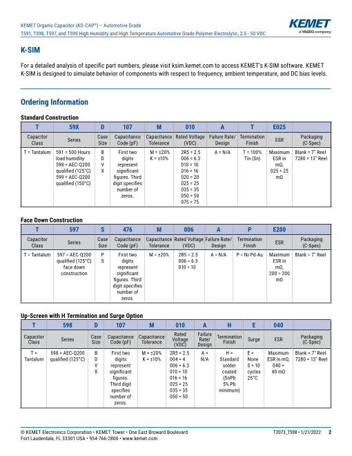
Ordering Information
Standard Construction
T 59X D 107 M 010 A T E025
Capacitor Series Case Capacitance Capacitance Rated Voltage Failure Rate/ Termination Packaging
Class Size Code (pF) Tolerance (VDC) Design Finish ESR (C-Spec)
T = Tantalum 591 = 500 Hours B First two M = ±20% 2R5 = 2.5 A = N/A T = 100% Maximum Blank = 7" Reel
load humidity D digits K = ±10% 006 = 6.3 Tin (Sn) ESR in 7280 = 13" Reel
598 = AEC-Q200 V represent 010 = 10 mΩ,
qualified (125°C) X significant 016 = 16 025 = 25
599 = AEC-Q200 figures. Third 020 = 20 mΩ
qualified (150°C) digit specifies 025 = 25
number of 035 = 35
zeros. 050 = 50
075 = 75
Face Down Construction
T 597 S 476 M 006 A P E200
Capacitor Series Case Capacitance Capacitance Rated Voltage Failure Rate/ Termination Packaging
Class Size Code (pF) Tolerance (VDC) Design Finish ESR (C-Spec)
T = Tantalum 597 = AEC-Q200 P First two M = ±20% 2R5 = 2.5 A = N/A P = Ni-Pd-Au Maximum Blank = 7" Reel
qualified (125°C) S digits 006 = 6.3 ESR in
face down represent 010 = 10 mΩ,
construction significant 200 = 200
figures. Third mΩ
digit specifies
number of
zeros.
Up-Screen with H Termination and Surge Option
T 598 D 107 M 010 A H E 040
Capacitor Series Case Capacitance Capacitance Rated Failure
Voltage Rate/ Termination Surge ESR Packaging
Class Size Code (pF) Tolerance (VDC) Design Finish (C-Spec)
T = 598 = AEC-Q200 B First two M = ±20% 2R5 = 2.5 A = H = E = Maximum Blank = 7" Reel
Tantalum qualified (125°C) D digits K = ±10% 004 = 4 N/A Standard None ESR in mΩ, 7280 = 13" Reel
V represent 006 = 6.3 solder S = 10 040 =
X significant 010 = 10 coated cycles 40 mΩ
figures. 016 = 16 (SnPb 25°C
Third digit 025 = 25 5% Pb
specifies 035 = 35 minimum)
number of 050 = 50
zeros.
© KEMET Electronics Corporation • KEMET Tower • One East Broward Boulevard T2073_T59X • 1/21/2022 2
Fort Lauderdale, FL 33301 USA • 954-766-2800 • www.kemet.com
Page3
Performance Characteristics、Environmental Compliance
KEMET Organic Capacitor (KO-CAP®) – Automotive Grade
T591, T598, T597, and T599 High Humidity and High Temperature Automotive Grade Polymer Electrolytic, 2.5 - 50 VDC
Performance Characteristics
Item Performance Characteristics
Operating Temperature −55°C to 105°C/125°C/150°C
Rated Capacitance Range 4.7 – 470 µF at 120 Hz/25°C
Capacitance Tolerance K Tolerance (10%), M Tolerance (20%)
Rated Voltage Range 2.5 – 75 V
DF (120 Hz) Refer to Part Number Electrical Specification Table
ESR (100 kHz) Refer to Part Number Electrical Specification Table
Leakage Current ≤ 0.1 CV (µA) at rated voltage after 5 minutes
T597: ≤ 0.3 CV (µA) at rated voltage after 5 minutes
Environmental Compliance
• RoHS compliant when ordered with 100% Sn (AT) or Ni-Pd-Au (AP) termination
• End of Life Vehicle compliant according to 2003/53/EC as amended by (EU) 2016/774 when ordered with 100% Sn (AT)
or Ni-Pd-Au (AP) termination
• NOT RoHS or End of Life Vehicle compliant when ordered with SnPb termination (AH) due to the content of Lead
(CAS # 7439-92-1) in the termination
• REACH Candidate list of substance of very high concern, Lead (CAS# 7439-92-1) contained when ordered with
SnPb termination (AH)
• Halogen-free
© KEMET Electronics Corporation • KEMET Tower • One East Broward Boulevard T2073_T59X • 1/21/2022 3
Fort Lauderdale, FL 33301 USA • 954-766-2800 • www.kemet.com
Page4
Qualification
KEMET Organic Capacitor (KO-CAP®) – Automotive Grade
T591, T598, T597, and T599 High Humidity and High Temperature Automotive Grade Polymer Electrolytic, 2.5 - 50 VDC
Qualification
Test Condition Characteristics
Temperature: 105°C,125°C,150°C*2 Δ C/C Within −20%/+10% of initial value
Voltage: 1.0 Rated Voltage
Endurance 2/3 Rated Voltage for ≥ 125°C rating PN DF Within 2 x initial limit
Time: 2,000 Hours DCL Within 2 x initial limit
1,000 Hours*5
ESR Within 2 x initial limit
Temperature: 105°C,125°C,150°C*2 Δ C/C Within −20%/+10% of initial value
Storage Life Voltage: 0 Voltage DF Within 2 x initial limit
Time: 2,000 Hours DCL Within 2 x initial limit
1,000 Hours*5
ESR Within 2 x initial limit
Δ C/C Within −5%/+35% of initial value
85°C, 85% RH, load, 500 hours (T591) DF Within 1.5 x initial limits
Humidity 85°C, 85% RH, load, 1,000 hours
(T597, T598, T599) DCL Within initial limit
ESR Within 2 x initial limit
Δ C/C Within −10%/+20% of initial value
Moisture MIL–STD–202, Method 106, DF Within initial limit
Resistance*1 65°C, 90 – 100% RH, no load, 10 cycles DCL Within initial limit
ESR Within 2 x initial limit
Δ C/C Within −20%/+10% of initial value
Temperature JESD22, Test Method A104, DF Within initial limits
Cycling −55°C to +105°C/+125°C/+150°C*2, 1,000 cycles DCL Within initial limit
ESR Within 2 x initial limits
105°C, 1.32 x rated voltage, 1,000 cycles, Δ C/C Within −20%/+10% of initial value
33 Ω in series DF Within initial limits
Surge Voltage 125°C/150°C, 1.32 x (0.67 x VR), 1,000 cycles, DCL Within initial limits
33 Ω in series*2
ESR Within initial limits
Extreme temperature exposure at a succession +25°C −55°C +85°C +105°C/+125°C/+150°C*2
Temperature of continuous steps at Δ C/C IL*3 ±20% ±20% ±30%*4
Stability +25°C, −55°C, +25°C, +85°C, DF IL IL 1.2 x IL 1.5 x IL
+105°C/+125°C/+150°C*2, +25°C DCL IL N/A 10 x IL 10 x IL
AEC–Q200 (MIL–STD–202, Method 213, Figure 1, Δ C/C Within ±10% of initial value
Mechanical Condition F.) DF Within initial limits
Shock/ AEC–Q200 (MIL–STD–202, Method 204, 5 G for 20
Vibration ESR Within initial limits
minutes/12 cycles each of 3 orientations.
Test from 10 – 2, 000 Hz.) DCL Within initial limits
*1 This test is not applicable to the T591 series ratings
*2 Refer to part number specifications for individual temperature classification
*3 IL = Initial limit
*4 For T599 (≤ 16 V) apply −30%/+40%
*5 1,000 hours for Endurance and Storage is applicable to T597 series offerings & PN T599X336M035ATE065
© KEMET Electronics Corporation • KEMET Tower • One East Broward Boulevard T2073_T59X • 1/21/2022 4
Fort Lauderdale, FL 33301 USA • 954-766-2800 • www.kemet.com
Page5
Reliability
KEMET Organic Capacitor (KO-CAP®) – Automotive Grade
T591, T598, T597, and T599 High Humidity and High Temperature Automotive Grade Polymer Electrolytic, 2.5 - 50 VDC
Reliability
KO-CAP capacitors have an average failure rate of 0.5 %/1,000 hours at category voltage, UC, and category temperature,
TC. These capacitors are qualified using industry test standards at UC and TC. The minimum test time (1,000 hours or 2,000
hours) is dependent on the product.
The actual life expectancy of KO-CAP capacitors increases when application voltage, UA, and application temperature, TA,
are lower than UC and TC. As a general guideline, when UA < 0.9 * UC and TA < 85°C, the life expectancy will typically exceed
the useful lifetime of most hardware (> 10 years).
The lifetime of a KO-CAP capacitor at a specific application voltage and temperature can be modeled using the equations
below. A failure is defined as passing enough current to blow a 1-amp fuse. The calculation is an estimation based on
empirical results and is not a guarantee.
( UC)n E 1 1
VAF = [ a
( )]
UA TAF = e k 273+TA 273+TC
where: where:
VAF = acceleration factor due to voltage, unitless TAF = acceleration factor due to temperature, unitless
Ea = activation energy, 1.4 eV
UC = category voltage, volt k = Boltzmann’s constant, 8.617E-5 eV/K
UA = application voltage, volt TA = application temperature, °C
n = exponent, 16 TC = category temperature, °C
AF = VAF * TAF LifeU ,T = Life * AF
A A UC ,TC
where:
where: LifeUA, TA = estimated life application voltage
AF = acceleration factor, unitless and temperature, years
TAF = accerlation factor due to temperature, unitless LifeUC, TC = guaranteed life category voltage
and temperature, years
VAF = acceleration factor due to voltage, unitless
AF = acceleration factor, unitless
Reliability Table 1 – Common Temperature Range Classifications
85°C (T )/ Rated voltage (UR) 2.5 4.0 6.3 8.0 10.0 12.5 16.0 20.0 25.0 35.0 50.0 63.0 75.0
R
85°C (TC) Category voltage (UC) 2.5 4.0 6.3 8.0 10.0 12.5 16.0 20.0 25.0 35.0 50.0 63.0 75.0
105°C (T )/ Rated voltage (UR) 2.5 4.0 6.3 8.0 10.0 12.5 16.0 20.0 25.0 35.0 50.0 63.0 75.0
R
105°C (TC) Category voltage (UC) 2.5 4.0 6.3 8.0 10.0 12.5 16.0 20.0 25.0 35.0 50.0 63.0 75.0
105°C (T )/ Rated voltage (UR) 2.5 4.0 6.3 8.0 10.0 12.5 16.0 20.0 25.0 35.0 50.0 63.0 75.0
R
125°C (TC) Category voltage (UC) 1.7 2.7 4.2 5.4 6.7 8.4 10.7 13.4 16.8 23.5 33.5 42.2 50.3
105°C (T )/ Rated voltage (UR) 2.5 4.0 6.3 8.0 10.0 12.5 16.0 20.0 25.0 35.0 50.0 63.0 75.0
R
150°C (TC) Category voltage (UC) 1.7 2.7 4.2 5.4 6.7 8.4 10.7 13.4 16.8 23.5 33.5 42.2 50.3
Terms:
Category voltage, UC : Maximum recommended peak DC operating voltage for continuous operation at the category temperature, TC.
Rated voltage, UR : Maximum recommended peak DC operating voltage for continuous operation up to the rated temperature, TR.
Category temperature, TC : Maximum recommended operating temperature. Voltage derating may be required at TC.
Rated temperature, TR : Maximum recommended operating temperature without voltage derating. TR is equal to or lower than TC.
© KEMET Electronics Corporation • KEMET Tower • One East Broward Boulevard T2073_T59X • 1/21/2022 5
Fort Lauderdale, FL 33301 USA • 954-766-2800 • www.kemet.com
Page6
Certification、Electrical Characteristics
KEMET Organic Capacitor (KO-CAP®) – Automotive Grade
T591, T598, T597, and T599 High Humidity and High Temperature Automotive Grade Polymer Electrolytic, 2.5 - 50 VDC
Certification
KEMET's internal qualification plan for this polymer electrolytic series of capacitors follows AEC-Q200 guidelines.
For T591 the humidity bias is limited to a maximum of 500 hours.
For T597 and T598 the qualification plan is fully compliant with AEC-Q200 with maximum operational temperature of 125°C.
For T599 the qualification plan is fully compliant with AEC-Q200 with maximum operational temperature of 150°C.
Electrical Characteristics
ESR vs. Frequency – T591 Capacitance vs. Frequency – T591
I M P E D A N C E _ E S R v s F r e q u e n c y
1000
C a p a c i t a n c e v s F r e q u e n c y
1000
100 IMP
D, 10 µF
B , 47 µF
D, 47 µF
10 D, 100 µF
V, 220 µF
100
1
0.1 10
0.01
1
100 1,000 10,000 100,000 1,000,000 10,000,000
Frequency (Hz)
0.001
100 1,000 10,000 100,000 1,000,000 10,000,000
Frequency (Hz)
ESR vs. Frequency – T597 Capacitance vs. Frequency – T597
IMPEDANCE_ESR vs Frequency
100
Capacitance vs Frequency
1,000
10 47 µF/6 V
33 µF/6 V
22 µF/6 V
100 22 µF/10 V
1
10
0.1
1
100 1,000 10,000 100,000 1,000,000
Frequency (Hz)
0.01
100 1,000 10,000 100,000 1,000,000 10,000,000
Frequency (Hz)
© KEMET Electronics Corporation • KEMET Tower • One East Broward Boulevard T2073_T59X • 1/21/2022 6
Fort Lauderdale, FL 33301 USA • 954-766-2800 • www.kemet.com
Impedance , ESR (Ohms)
Impedance, ESR (Ohms)
Capacitance (µF)
Capacitance (µF)
Page7
KEMET Organic Capacitor (KO-CAP®) – Automotive Grade
T591, T598, T597, and T599 High Humidity and High Temperature Automotive Grade Polymer Electrolytic, 2.5 - 50 VDC
Electrical Characteristics cont.
ESR vs. Frequency – T598 Capacitance vs. Frequency – T598
I M P E D A N C E _ E S R v s F r e q u e n c y C a p a c i t a n c e v s F r e q u e n c y
100
1000
10
100
1
10 B 47µF
D 100µF / 16V
0.1 D 100µF / 10V
D 220µF/ 10V
1
0.01
0.1
0.001 100 1000 10000 100000 1000000 10000000
100 1000 10000 100000 1000000 10000000 Frequency (Hz)
Frequency (Hz)
ESR vs. Frequency – T599 Capacitance vs. Frequency – T599
I M P E D A N C E _ E S R v s F r e q u e n c y
C a p a c i t a n c e v s F r e q u e n c y
100 100
10
10 X, 33µF
X, 33 µF _ IMP
1 X, 33 µF _ ESR
1
0.1
0.01 0
100 1,000 10,000 100,000 1,000,000 10,000,000 100 1,000 10,000 100,000 1,000,000 10,000,000
Frequency (Hz)
Frequency (Hz)
© KEMET Electronics Corporation • KEMET Tower • One East Broward Boulevard T2073_T59X • 1/21/2022 7
Fort Lauderdale, FL 33301 USA • 954-766-2800 • www.kemet.com
Impedance & ESR (ohms) Impedance & ESR (Ohms)
Capacitance (µF)
Capacitance (µF)
Page8
Dimensions – Millimeters (Inches)
KEMET Organic Capacitor (KO-CAP®) – Automotive Grade
T591, T598, T597, and T599 High Humidity and High Temperature Automotive Grade Polymer Electrolytic, 2.5 - 50 VDC
Dimensions – Millimeters (Inches)
Metric will govern
T591 / T598 / T599
CATHODE (-) END VIEW SIDE VIEW ANODE (+) END VIEW BOTTOM VIEW
W B A
B
Glue pad
H shape/design at F
KEMET's option
P
Termination cutout
X T at KEMET's option,
S S either end R
L
Case Size Component Dimensions Typical
Weight
KEMET EIA L W H F ±0.1 S ±0.3 B ±0.15 X P R T A
±(0.004) ±(0.012) (Ref) ±0.006 (Ref) (Ref) (Ref) (Ref) (Minimum) (mg)
B 3528–21 3.5 ±0.2 2.8 ±0.2 1.9 ±0.2 2.2 0.8
(0.138 ±0.008) (0.110 ±0.008) (0.075 ±0.008) (0.087) (0.031) 0.4 (0.016) 0.10 ±0.10 0.5 1.0 0.13 1.1
(0.004 ±0.004) (0.020) (0.039) (0.005) (0.043) 95
D 7343–31 7.3 ±0.3 4.3 ±0.3 2.8 ±0.3 2.4 1.3 0.5 (0.020) 0.10 ±0.10 0.9 1.0 0.13 3.8
(0.287 ±0.012) (0.169 ±0.012) (0.110 ±0.012) (0.094) (0.051) (0.004 ±0.004) (0.035) (0.039) (0.005) (0.150) 435
V 7343-20 7.3 ±0.3 4.3 ±0.3 1.9 ±0.1 2.4 1.3 0.05 0.13 3.8
(0.287 ±0.012) (0.169 ±0.012) (0.075 ±0.004) (0.094) (0.051) N/A (0.002) N/A N/A (0.005) (0.150) 274
X 7343-43 7.3 ±0.3 4.3 ±0.3 4.0 ±0.3 2.4 1.3 0.5 (0.020) 0.10 ±0.10 1.7 1.0 0.13 3.8
(0.287 ±0.012) (0.169 ±0.012) (0.157±0.012) (0.094) (0.051) (0.004 ±0.004) (0.067) (0.039) (0.005) (0.150) 554
Notes: Reference (Ref) – Dimensions provided for reference only. For low profile cases, no dimensions are provided for B, P, or R, because these cases
do not have a bevel or a notch.
These weights are provided as reference. If exact weights are needed, please contact your KEMET sales representative.
T597
END VIEW SIDE VIEW BOTTOM VIEW
H
F
W L
S S
Case Size Component Dimensions Weight
KEMET EIA L W H F ±0.1 (±0.004) S ±0.2 (±0.008) (mg)
P 2012-10 2.0 ±0.2 1.2 ±0.2 0.9 ±0.1 0.9 0.55
(0.079±0.008) (0.047±0.008) (0.035±0.004) (0.035) (0.022) 11.3
S 3216-12 3.2 ± 0.2 1.6 ±0.2 1.1 ±0.1 1.2 0.8
(0.126 ±0.008) (0.063 ±0.008) (0.043 ±0.004) (0.047) (0.031) 26.2
© KEMET Electronics Corporation • KEMET Tower • One East Broward Boulevard T2073_T59X • 1/21/2022 8
Fort Lauderdale, FL 33301 USA • 954-766-2800 • www.kemet.com
Page9
Table 1 – Ratings & Part Number Reference
KEMET Organic Capacitor (KO-CAP®) – Automotive Grade
T591, T598, T597, and T599 High Humidity and High Temperature Automotive Grade Polymer Electrolytic, 2.5 - 50 VDC
Table 1 – Ratings & Part Number Reference
Case Maximum
Rated Rated Code/ KEMET Part DC Allowable Maximum AEC-Q200
Voltage Cap Case Number Leakage DF ESR Ripple MSL Operating Qualified
Size Current Temp
VDC at 105°C µF KEMET/EIA µA at +25°C % at +25°C mΩ at +25°C (rms)
Max/5 Minutes 120 Hz Max 100 kHz Max mA at +45°C Reflow Temp
≤ 260°C °C T597/T598/T599
Only1
100 kHz
105°C
2.5 100 B/3528-21 T591B107M2R5ATE055 25 8 55 1,570 3 105
2.5 100 B/3528-21 T591B107M2R5ATE070 25 8 70 1,390 3 105
2.5 220 B/3528-21 T591B227M2R5ATE025 55 8 25 2,320 3 105
2.5 220 V/7343-20 T591V227M2R5ATE009 55 10 9 6,670 3 105
2.5 220 V/7343-20 T591V227M2R5ATE012 55 10 12 5,770 3 105
2.5 220 V/7343-20 T591V227M2R5ATE015 55 10 15 5,160 3 105
4 100 B/3528-21 T591B107M004ATE070 40 10 70 1,390 3 105
4 220 V/7343-20 T591V227M004ATE018 88 10 18 4,710 3 105
4 220 V/7343-20 T591V227M004ATE025 88 10 25 4,000 3 105
6.3 220 B/3528-21 T591B227M006ATE035 139 8 35 1,960 3 105
125°C
2.5 100 B/3528-21 T598B107M2R5ATE045 25 8 45 1,730 3 125 •
2.5 100 B/3528-21 T591B107M2R5ATE045 25 8 45 1,730 3 125
2.5 100 B/3528-21 T598B107M2R5ATE055 25 8 55 1,570 3 125 •
2.5 100 B/3528-21 T598B107M2R5ATE070 25 8 70 1,390 3 125 •
2.5 220 B/3528-21 T598B227M2R5ATE025 55 10 25 2,320 3 125 •
2.5 220 D/7343-31 T598D227M2R5ATE009 55 10 9 7,070 3 125 •
2.5 220 D/7343-31 T598D227M2R5ATE012 55 10 12 6,120 3 125 •
2.5 220 D/7343-31 T591D227M2R5ATE009 55 10 9 7,070 3 125
2.5 220 D/7343-31 T591D227M2R5ATE012 55 10 12 6,120 3 125
2.5 330 V/7343-20 T591V337M2R5ATE012 82.5 10 12 5,770 3 125
2.5 330 V/7343-20 T591V337M2R5ATE025 82.5 10 25 4,000 3 125
2.5 330 D/7343-31 T598D337M2R5ATE009 82.5 10 9 7,070 3 125 •
2.5 330 D/7343-31 T598D337M2R5ATE012 82.5 10 12 6,120 3 125 •
2.5 330 D/7343-31 T591D337M2R5ATE009 82.5 10 9 7,070 3 125
2.5 330 D/7343-31 T591D337M2R5ATE012 82.5 10 12 6,120 3 125
2.5 330 D/7343-31 T591D337M2R5ATE015 82.5 10 15 5,480 3 125
2.5 330 D/7343-31 T591D337M2R5ATE018 82.5 10 18 5,000 3 125
2.5 470 D/7343-31 T598D477M2R5ATE006 117.5 10 6 8,660 3 125 •
2.5 470 D/7343-31 T591D477M2R5ATE006 117.5 10 6 8,660 3 125
2.5 470 D/7343-31 T591D477M2R5ATE009 117.5 10 9 7,070 3 125
2.5 470 D/7343-31 T598D477M2R5ATE009 117.5 10 9 7,070 3 125 •
4 100 B/3528-21 T598B107M004ATE045 40 8 45 1,730 3 125 •
4 100 B/3528-21 T598B107M004ATE055 40 8 55 1,570 3 125 •
4 100 B/3528-21 T598B107M004ATE070 40 8 70 1,390 3 125 •
4 100 B/3528-21 T591B107M004ATE045 40 8 45 1,730 3 125
4 100 B/3528-21 T591B107M004ATE055 40 8 55 1,570 3 125
4 150 B/3528-21 T598B157M004ATE045 60 8 45 1,730 3 125 •
4 150 B/3528-21 T598B157M004ATE055 60 8 55 1,570 3 125 •
4 150 B/3528-21 T598B157M004ATE070 60 8 70 1,390 3 125 •
4 150 B/3528-21 T591B157M004ATE045 60 8 45 1,730 3 125
4 150 B/3528-21 T591B157M004ATE055 60 8 55 1,570 3 125
4 150 B/3528-21 T591B157M004ATE070 60 8 70 1,390 3 125
4 330 V/7343-20 T598V337M004ATE025 132 10 25 4,000 3 125 •
4 330 V/7343-20 T598V337M004ATE045 132 10 45 2,980 3 125 •
4 330 V/7343-20 T591V337M004ATE025 132 10 25 4,000 3 125
4 330 V/7343-20 T591V337M004ATE045 132 10 45 2,980 3 125
4 470 D/7343-31 T598D477M004ATE025 188 10 25 4,240 3 125 •
VDC at 105°C µF KEMET/EIA µA at +25°C % at +25°C mΩ at +25°C (rms) Reflow Temp T597/T598/T599
Max/5 Minutes 120 Hz Max 100 kHz Max mA at +45°C
100 kHz ≤ 260°C °C Only1
Rated Case Code/ Maximum Maximum
Voltage Rated Cap Case Size KEMET Part Number DC Leakage DF ESR Allowable MSL Operating AEC–Q200
Ripple Current Temp Qualified
(1) To complete KEMET part number, insert M for ±20% or K for ±10%. Designates capacitance tolerance.
(2) To complete KEMET part number, insert E = None or S = 10 cycles +25°C ±5°C. Designates surge current option.
1 T598 = AEC-Q200 qualified. T599 AEC-Q200 qualified 150°C and T591 = limited to 500 hours at 85°C/85% RH load.
Refer to Ordering Information for additional detail.
© KEMET Electronics Corporation • KEMET Tower • One East Broward Boulevard T2073_T59X • 1/21/2022 9
Fort Lauderdale, FL 33301 USA • 954-766-2800 • www.kemet.com
Page10
KEMET Organic Capacitor (KO-CAP®) – Automotive Grade
T591, T598, T597, and T599 High Humidity and High Temperature Automotive Grade Polymer Electrolytic, 2.5 - 50 VDC
Table 1 – Ratings & Part Number Reference cont.
Case Maximum
Rated Rated Code/ KEMET Part DC Allowable Maximum AEC-Q200
Voltage Cap Case Number Leakage DF ESR Ripple MSL Operating Qualified
Size Current Temp
(rms)
VDC at 105°C µF KEMET/EIA µA at +25°C % at +25°C mΩ at +25°C
Max/5 Minutes 120 Hz Max 100 kHz Max mA at +45°C Reflow Temp °C T597/T598/T599
100 kHz ≤ 260°C Only1
125°C
4 470 D/7343-31 T591D477M004ATE025 188 10 25 4,240 3 125
6.3 22 B/3528-21 T598B226M006ATE070 13.9 8 70 1,390 3 125 •
6.3 22 B/3528-21 T591B226M006ATE070 13.9 8 70 1,390 3 125
6.3 33 B/3528-21 T598B336M006ATE070 20.8 8 70 1,390 3 125 •
6.3 33 B/3528-21 T598B336M006ATE080 20.8 8 80 1,300 3 125 •
6.3 33 B/3528-21 T591B336M006ATE070 20.8 8 70 1,390 3 125
6.3 33 B/3528-21 T591B336M006ATE080 20.8 8 80 1,300 3 125
6.3 47 B/3528-21 T598B476M006ATE070 29.6 8 70 1,390 3 125 •
6.3 47 B/3528-21 T591B476M006ATE070 29.6 8 70 1,390 3 125
6.3 68 B/3528-21 T598B686M006ATE070 43 8 70 1,390 3 125 •
6.3 68 B/3528-21 T591B686M006ATE070 43 8 70 1,390 3 125
6.3 100 B/3528-21 T598B107M006ATE045 63 8 45 1,730 3 125 •
6.3 100 B/3528-21 T598B107M006ATE055 63 8 55 1,570 3 125 •
6.3 100 B/3528-21 T598B107M006ATE070 63 8 70 1,390 3 125 •
6.3 100 B/3528-21 T591B107M006ATE045 63 8 45 1,730 3 125
6.3 100 B/3528-21 T591B107M006ATE055 63 8 55 1,570 3 125
6.3 100 B/3528-21 T591B107M006ATE070 63 8 70 1,390 3 125
6.3 150 B/3528-21 T598B157M006ATE045 94.5 8 45 1,730 3 125 •
6.3 150 B/3528-21 T598B157M006ATE055 94.5 8 55 1,570 3 125 •
6.3 150 B/3528-21 T598B157M006ATE070 94.5 8 70 1,390 3 125 •
6.3 150 B/3528-21 T591B157M006ATE045 94.5 8 45 1,730 3 125
6.3 150 B/3528-21 T591B157M006ATE055 94.5 8 55 1,570 3 125
6.3 150 B/3528-21 T591B157M006ATE070 94.5 8 70 1,390 3 125
6.3 150 V/7343-20 T598V157M006ATE025 94.5 10 25 4,000 3 125 •
6.3 150 V/7343-20 T598V157M006ATE045 94.5 10 45 2,980 3 125 •
6.3 150 V/7343-20 T591V157M006ATE025 94.5 10 25 4,000 3 125
6.3 150 V/7343-20 T591V157M006ATE045 94.5 10 45 2,980 3 125
6.3 150 D/7343-31 T598D157M006ATE025 94.5 10 25 4,240 3 125 •
6.3 150 D/7343-31 T598D157M006ATE045 94.5 10 45 3,160 3 125 •
6.3 150 D/7343-31 T591D157M006ATE025 94.5 10 25 4,240 3 125
6.3 150 D/7343-31 T591D157M006ATE045 94.5 10 45 3,160 3 125
6.3 220 B/3528-21 T591B227M006ATE045 139 8 45 1,730 3 125
6.3 220 B/3528-21 T591B227M006ATE070 139 8 70 1,390 3 125
6.3 220 D/7343-31 T598D227M006ATE025 139 10 25 4,240 3 125 •
6.3 220 D/7343-31 T598D227M006ATE040 139 10 40 3,350 3 125 •
6.3 220 D/7343-31 T598D227M006ATE080 139 10 80 2,370 3 125 •
6.3 220 D/7343-31 T591D227M006ATE025 139 10 25 4,240 3 125
6.3 220 D/7343-31 T591D227M006ATE040 139 10 40 3,350 3 125
6.3 220 D/7343-31 T591D227M006ATE080 139 10 80 2,370 3 125
6.3 220 V/7343-20 T598V227M006ATE025 139 10 25 4,000 3 125 •
6.3 220 V/7343-20 T598V227M006ATE045 139 10 45 2,980 3 125 •
6.3 220 V/7343-20 T591V227M006ATE025 139 10 25 4,000 3 125
6.3 220 V/7343-20 T591V227M006ATE045 139 10 45 2,980 3 125
6.3 330 D/7343-31 T598D337M006ATE025 208 10 25 4,240 3 125 •
6.3 330 D/7343-31 T598D337M006ATE040 208 10 40 3,350 3 125 •
6.3 330 D/7343-31 T598D337M006ATE080 208 10 80 2,370 3 125 •
6.3 330 D/7343-31 T591D337M006ATE025 208 10 25 4,240 3 125
6.3 330 D/7343-31 T591D337M006ATE040 208 10 40 3,350 3 125
VDC at 105°C µF KEMET/EIA µA at +25°C % at +25°C mΩ at +25°C (rms) Reflow Temp T597/T598/T599
Max/5 Minutes 120 Hz Max 100 kHz Max mA at +45°C
100 kHz ≤ 260°C °C Only1
Rated Maximum Maximum
Voltage Rated Cap Case Code/
Case Size KEMET Part Number DC Leakage DF ESR Allowable MSL Operating AEC–Q200
Ripple Current Temp Qualified
(1) To complete KEMET part number, insert M for ±20% or K for ±10%. Designates capacitance tolerance.
(2) To complete KEMET part number, insert E = None or S = 10 cycles +25°C ±5°C. Designates surge current option.
1 T598 = AEC-Q200 qualified. T599 AEC-Q200 qualified 150°C and T591 = limited to 500 hours at 85°C/85% RH load.
Refer to Ordering Information for additional detail.
© KEMET Electronics Corporation • KEMET Tower • One East Broward Boulevard T2073_T59X • 1/21/2022 10
Fort Lauderdale, FL 33301 USA • 954-766-2800 • www.kemet.com
Page11
KEMET Organic Capacitor (KO-CAP®) – Automotive Grade
T591, T598, T597, and T599 High Humidity and High Temperature Automotive Grade Polymer Electrolytic, 2.5 - 50 VDC
Table 1 – Ratings & Part Number Reference cont.
Case Maximum
Rated Rated Code/ KEMET Part DC Allowable Maximum AEC-Q200
Voltage Cap Case Number Leakage DF ESR Ripple MSL Operating
Temp Qualified
Size Current
(rms)
VDC at 105°C µF KEMET/EIA µA at +25°C % at +25°C mΩ at +25°C mA at +45°C Reflow Temp °C T597/T598/T599
Max/5 Minutes 120 Hz Max 100 kHz Max 1
100 kHz ≤ 260°C Only
125°C
6.3 330 D/7343-31 T591D337M006ATE080 208 10 80 2,370 3 125
6.3 680 X/7343-43 T598X687M006ATE025 428 10 25 4,470 3 125 •
6.3 680 X/7343-43 T591X687M006ATE025 428 10 25 4,470 3 125
10 22 B/3528-21 T598B226M010ATE070 22 8 70 1,390 3 125 •
10 22 B/3528-21 T591B226M010ATE070 22 8 70 1,390 3 125
10 33 B/3528-21 T598B336M010ATE070 33 8 70 1,390 3 125 •
10 33 B/3528-21 T598B336M010ATE080 33 8 80 1,300 3 125 •
10 33 B/3528-21 T591B336M010ATE070 33 8 70 1,390 3 125
10 33 B/3528-21 T591B336M010ATE080 33 8 80 1,300 3 125
10 47 B/3528-21 T598B476M010ATE070 47 8 70 1,390 3 125 •
10 47 B/3528-21 T591B476M010ATE070 47 8 70 1,390 3 125
10 100 D/7343-31 T598D107M010ATE025 100 10 25 4,240 3 125 •
10 100 D/7343-31 T598D107M010ATE040 100 10 40 3,350 3 125 •
10 100 D/7343-31 T598D107M010ATE080 100 10 80 2,370 3 125 •
10 100 D/7343-31 T591D107M010ATE025 100 10 25 4,240 3 125
10 100 D/7343-31 T591D107M010ATE040 100 10 40 3,350 3 125
10 100 D/7343-31 T591D107M010ATE080 100 10 80 2,370 3 125
10 100 V/7343-20 T598V107M010ATE025 100 10 25 4,000 3 125 •
10 100 V/7343-20 T598V107M010ATE045 100 10 45 2,980 3 125 •
10 100 V/7343-20 T591V107M010ATE025 100 10 25 4,000 3 125
10 100 V/7343-20 T591V107M010ATE045 100 10 45 2,980 3 125
10 150 D/7343-31 T598D157M010ATE025 150 10 25 4,240 3 125 •
10 150 D/7343-31 T598D157M010ATE045 150 10 45 3,160 3 125 •
10 150 D/7343-31 T591D157M010ATE025 150 10 25 4,240 3 125
10 150 D/7343-31 T591D157M010ATE045 150 10 45 3,160 3 125
10 150 V/7343-20 T598V157M010ATE025 150 10 25 4,000 3 125 •
10 150 V/7343-20 T598V157M010ATE045 150 10 45 2,980 3 125 •
10 150 V/7343-20 T591V157M010ATE025 150 10 25 4,000 3 125
10 150 V/7343-20 T591V157M010ATE045 150 10 45 2,980 3 125
10 220 D/7343-31 T598D227M010ATE025 220 10 25 4,240 3 125 •
10 220 D/7343-31 T598D227M010ATE040 220 10 40 3,350 3 125 •
10 220 D/7343-31 T598D227M010ATE080 220 10 80 2,370 3 125 •
10 220 D/7343-31 T591D227M010ATE025 220 10 25 4,240 3 125
10 220 D/7343-31 T591D227M010ATE040 220 10 40 3,350 3 125
10 220 D/7343-31 T591D227M010ATE080 220 10 80 2,370 3 125
16 47 D/7343-31 T598D476M016ATE070 75.2 10 70 2,530 3 125 •
16 47 D/7343-31 T591D476M016ATE070 75.2 10 70 2,530 3 125
16 100 D/7343-31 T598D107M016ATE050 160 10 50 3,000 3 125 •
16 100 D/7343-31 T591D107M016ATE050 160 10 50 3,000 3 125
16 150 D/7343-31 T598D157M016ATE065 240 10 65 2,630 3 125 •
16 150 D/7343-31 T591D157M016ATE065 240 10 65 2,630 3 125
20 47 D/7343-31 T591D476M020ATE050 94 10 50 3,000 3 125
20 68 D/7343-31 T591D686M020ATE040 136 10 40 3,350 3 125
20 68 D/7343-31 T591D686M020ATE050 136 10 50 3,000 3 125
25 22 D/7343-31 T591D226M025ATE060 55 10 60 2,740 3 125
25 33 D/7343-31 T598D336M025ATE060 82.5 10 60 2,740 3 125 •
25 33 D/7343-31 T591D336M025ATE060 82.5 10 60 2,740 3 125
25 47 D/7343-31 T598D476M025ATE060 117.5 10 60 2,740 3 125 •
VDC at 105°C µF KEMET/EIA µA at +25°C % at +25°C mΩ at +25°C (rms) Reflow Temp T597/T598/T599
Max/5 Minutes 120 Hz Max 100 kHz Max mA at +45°C °C 1
100 kHz ≤ 260°C Only
Rated Case Code/ Maximum Maximum AEC–Q200
Voltage Rated Cap Case Size KEMET Part Number DC Leakage DF ESR Allowable MSL Operating
Ripple Current Temp Qualified
(1) To complete KEMET part number, insert M for ±20% or K for ±10%. Designates capacitance tolerance.
(2) To complete KEMET part number, insert E = None or S = 10 cycles +25°C ±5°C. Designates surge current option.
1 T598 = AEC-Q200 qualified. T599 AEC-Q200 qualified 150°C and T591 = limited to 500 hours at 85°C/85% RH load.
Refer to Ordering Information for additional detail.
© KEMET Electronics Corporation • KEMET Tower • One East Broward Boulevard T2073_T59X • 1/21/2022 11
Fort Lauderdale, FL 33301 USA • 954-766-2800 • www.kemet.com
Page12
KEMET Organic Capacitor (KO-CAP®) – Automotive Grade
T591, T598, T597, and T599 High Humidity and High Temperature Automotive Grade Polymer Electrolytic, 2.5 - 50 VDC
Table 1 – Ratings & Part Number Reference cont.
Case Maximum
Rated Rated Code/ KEMET Part DC DF ESR Allowable Maximum AEC-Q200
Voltage Cap Case Number Leakage Ripple MSL Operating
Temp Qualified
Size Current
µA at +25°C % at +25°C mΩ at +25°C (rms)
VDC at 105°C µF KEMET/EIA Reflow Temp T597/T598/T599
Max/5 Minutes 120 Hz Max 100 kHz Max mA at +45°C
100 kHz ≤ 260°C °C Only1
125°C
25 47 D/7343-31 T591D476M025ATE060 117.5 10 60 2,740 3 125
35 2.2 B/3528-21 T598B225M035ATE150 7.7 8 150 950 3 125 •
35 2.2 B/3528-21 T591B225M035ATE150 7.7 8 150 950 3 125
35 2.2 B/3528-21 T598B225M035ATE200 7.7 8 200 820 3 125 •
35 2.2 B/3528-21 T591B225M035ATE200 7.7 8 200 820 3 125
35 3.3 B/3528-21 T598B335M035ATE150 11.6 8 150 950 3 125 •
35 3.3 B/3528-21 T591B335M035ATE150 11.6 8 150 950 3 125
35 3.3 B/3528-21 T598B335M035ATE200 11.6 8 200 820 3 125 •
35 3.3 B/3528-21 T591B335M035ATE200 11.6 8 200 820 3 125
35 4.7 B/3528-21 T598B475M035ATE200 16.5 8 200 820 3 125 •
35 4.7 B/3528-21 T591B475M035ATE200 16.5 8 200 820 3 125
35 10 D/7343-31 T598D106M035ATE120 35 10 120 1,940 3 125 •
35 10 D/7343-31 T591D106M035ATE120 35 10 120 1,940 3 125
35 10 V/7343-20 T598V106M035ATE120 35 10 120 1,830 3 125 •
35 10 V/7343-20 T591V106M035ATE120 35 10 120 1,830 3 125
35 15 D/7343-31 T598D156M035ATE065 52.5 10 65 2,630 3 125 •
35 22 D/7343-31 T598D226M035ATE065 77 10 65 2,630 3 125 •
35 22 D/7343-31 T591D226M035ATE065 77 10 65 2,630 3 125
35 33 D/7343-31 T598D336M035ATE065 115.5 10 65 2,630 3 125 •
35 33 D/7343-31 T591D336M035ATE065 115.5 10 65 2,630 3 125
35 33 X/7343-43 T598X336M035ATE065 115.5 10 65 2,770 3 125 •
35 47 X/7343-43 T598X476M035ATE075 164.5 9 75 2,580 3 125 •
35 47 X/7343-43 T591X476M035ATE075 164.5 9 75 2,580 3 125
50 1.5 B/3528-21 T598B155(1)050ATE200 7.5 8 200 820 3 125 •
50 1.5 B/3528-21 T591B155(1)050ATE200 7.5 8 200 820 3 125
50 2.2 B/3528-21 T598B225M050ATE150 11 8 3 950 3 125 •
50 2.2 B/3528-21 T598B225M050ATE200 11 8 200 820 3 125 •
50 2.2 B/3528-21 T591B225M050ATE150 11 8 150 950 3 125
50 2.2 B/3528-21 T591B225M050ATE200 11 8 200 820 3 125
50 10 D/7343-31 T598D106M050ATE090 50 10 90 2,240 3 125 •
50 10 D/7343-31 T591D106M050ATE090 50 10 90 2,240 3 125
63 4.7 D/7343-31 T598D475M063ATE200 29.6 10 200 1,500 3 125 •
63 4.7 D/7343-31 T591D475M063ATE200 29.6 10 200 1,500 3 125
63 10 X/7343-43 T598X106M063ATE090 63 10 90 2,360 3 125 •
63 10 X/7343-43 T591X106M063ATE090 63 10 90 2,360 3 125
63 15 X/7343-43 T598X156M063ATE075 94.5 10 75 2,580 3 125 •
63 15 X/7343-43 T591X156M063ATE075 94.5 10 75 2,580 3 125
75 4.7 D/7343-31 T598D475M075ATE200 35.3 10 200 1,500 3 125 •
75 4.7 D/7343-31 T591D475M075ATE200 35.3 10 200 1,500 3 125
75 10 X/7343-43 T598X106M075ATE090 75.0 10 90 2,360 3 125 •
75 10 X/7343-43 T591X106M075ATE090 75.0 10 90 2,360 3 125
75 15 X/7343-43 T598X156M075ATE075 112.5 10 75 2,580 3 125 •
75 15 X/7343-43 T591X156M075ATE075 112.5 10 75 2,580 3 125
VDC at 105°C µF KEMET/EIA µA at +25°C % at +25°C mΩ at +25°C (rms)
mA at +45°C Reflow Temp °C T597/T598/T599
Max/5 Minutes 120 Hz Max 100 kHz Max 100 kHz ≤ 260°C Only1
Rated Case Code/ Maximum Maximum
Voltage Rated Cap Case Size KEMET Part Number DC Leakage DF ESR Allowable MSL Operating AEC–Q200
Ripple Current Temp Qualified
(1) To complete KEMET part number, insert M for ±20% or K for ±10%. Designates capacitance tolerance.
(2) To complete KEMET part number, insert E = None or S = 10 cycles +25°C ±5°C. Designates surge current option.
1 T598 = AEC-Q200 qualified. T599 AEC-Q200 qualified 150°C and T591 = limited to 500 hours at 85°C/85% RH load.
Refer to Ordering Information for additional detail.
© KEMET Electronics Corporation • KEMET Tower • One East Broward Boulevard T2073_T59X • 1/21/2022 12
Fort Lauderdale, FL 33301 USA • 954-766-2800 • www.kemet.com
Page13
KEMET Organic Capacitor (KO-CAP®) – Automotive Grade
T591, T598, T597, and T599 High Humidity and High Temperature Automotive Grade Polymer Electrolytic, 2.5 - 50 VDC
Table 1 – Ratings & Part Number Reference cont.
Case Maximum
Rated Rated Code/ KEMET Part DC Allowable Maximum AEC-Q200
Voltage Cap Case Number Leakage DF ESR Ripple MSL Operating Qualified
Size Current Temp
VDC at 105°C µF KEMET/EIA µA at +25°C % at +25°C mΩ at +25°C (rms)
Max/5 Minutes 120 Hz Max 100 kHz Max mA at +45°C Reflow Temp
≤ 260°C °C T597/T598/T599
100 kHz Only1
150°C
2.5 100 B/3528-21 T599B107(1)2R5ATE055 25 8 55 1,570 3 150 •
4 33 B/3528-21 T599B336M004ATE070 13.2 8 70 1,390 3 150 •
4 33 B/3528-21 T599B336M004ATE090 13.2 8 90 1,220 3 150 •
4 47 B/3528-21 T599B476M004ATE070 18.8 8 70 1,390 3 150 •
4 47 B/3528-21 T599B476M004ATE090 18.8 8 90 1,220 3 150 •
4 68 B/3528-21 T599B686M004ATE070 27.2 8 70 1,390 3 150 •
4 68 B/3528-21 T599B686M004ATE090 27.2 8 90 1,220 3 150 •
4 150 D/7343-31 T599D157M004ATE025 60 10 25 4,240 3 150 •
4 150 D/7343-31 T599D157M004ATE045 60 10 45 3,160 3 150 •
6.3 33 B/3528-21 T599B336M006ATE070 20.8 8 70 1,390 3 150 •
6.3 33 B/3528-21 T599B336M006ATE090 20.8 8 90 1,220 3 150 •
6.3 47 B/3528-21 T599B476M006ATE070 29.6 8 70 1,390 3 150 •
6.3 47 B/3528-21 T599B476M006ATE090 29.6 8 90 1,220 3 150 •
6.3 150 D/7343-31 T599D157M006ATE025 94.5 10 25 4,240 3 150 •
6.3 150 D/7343-31 T599D157M006ATE045 94.5 10 45 3,160 3 150 •
10 33 B/3528-21 T599B336M010ATE070 33 8 70 1,390 3 150 •
10 33 B/3528-21 T599B336M010ATE090 33 8 90 1,220 3 150 •
10 33 B/3528-21 T599B336M010ATE150 33 8 150 850 3 150 •
35 33 X/7343-43 T599X336M035ATE065 115.5 10 65 2,770 3 150 •
50 10 D/7343-31 T599D106M050ATE120 50 10 120 1,940 3 150 •
50 10 D/7343-31 T599D106M050ATE150 50 10 150 1,730 3 150 •
Facedown Construction
2.5 100 S/3216-12 T597S107M2R5APE100 75 10 100 770 3 125 •
6.3 22 P/2012-10 T597P226M006APE200 41.6 10 200 354 3 125 •
6.3 33 S/3216-12 T597S336M006APE100 62.4 10 100 770 3 125 •
6.3 33 S/3216-12 T597S336M006APE200 62.4 10 200 570 3 125 •
6.3 47 S/3216-12 T597S476M006APE100 88.8 10 100 770 3 125 •
6.3 47 S/3216-12 T597S476M006APE200 88.8 10 200 570 3 125 •
10 22 S/3216-12 T597S226M010APE200 66 10 200 570 3 125 •
T598 Up-Screen with H termination and Surge Current Screening Option
2.5 100 B/3528-21 T598B107M2R5AH(2)055 25 8 55 1,570 3 125 •
2.5 100 B/3528-21 T598B107M2R5AH(2)070 25 8 70 1,390 3 125 •
2.5 470 D/7343-31 T598D477M2R5AH(2)006 117.5 10 6 8,660 3 125 •
2.5 470 D/7343-31 T598D477M2R5AH(2)009 117.5 10 9 7,070 3 125 •
4 100 B/3528-21 T598B107M004AH(2)045 40 8 45 1,730 3 125 •
4 100 B/3528-21 T598B107M004AH(2)055 40 8 55 1,570 3 125 •
4 100 B/3528-21 T598B107M004AH(2)070 40 8 70 1,390 3 125 •
4 150 B/3528-21 T598B157M004AH(2)045 60 8 45 1,730 3 125 •
4 150 B/3528-21 T598B157M004AH(2)055 60 8 55 1,570 3 125 •
4 150 B/3528-21 T598B157M004AH(2)070 60 8 70 1,390 3 125 •
4 330 V/7343-20 T598V337M004AH(2)025 132 10 25 4,000 3 125 •
4 330 V/7343-20 T598V337M004AH(2)045 132 10 45 2,980 3 125 •
6.3 22 B/3528-21 T598B226M006AH(2)070 13.9 8 70 1,390 3 125 •
(rms)
VDC at 105°C µF KEMET/EIA µA at +25°C % at +25°C mΩ at +25°C Reflow Temp T597/T598/T599
Max/5 Minutes 120 Hz Max 100 kHz Max mA at +45°C °C
100 kHz ≤ 260°C Only1
Rated Maximum Maximum
Voltage Rated Cap Case Code/
Case Size KEMET Part Number DC Leakage DF ESR Allowable MSL Operating AEC–Q200
Ripple Current Temp Qualified
(1) To complete KEMET part number, insert M for ±20% or K for ±10%. Designates capacitance tolerance.
(2) To complete KEMET part number, insert E = None or S = 10 cycles +25°C ±5°C. Designates surge current option.
1 T598 = AEC-Q200 qualified. T599 AEC-Q200 qualified 150°C and T591 = limited to 500 hours at 85°C/85% RH load.
Refer to Ordering Information for additional detail.
Part Numbers marked in blue font are "Under Development." Engineering samples available upon request.
© KEMET Electronics Corporation • KEMET Tower • One East Broward Boulevard T2073_T59X • 1/21/2022 13
Fort Lauderdale, FL 33301 USA • 954-766-2800 • www.kemet.com
Page14
KEMET Organic Capacitor (KO-CAP®) – Automotive Grade
T591, T598, T597, and T599 High Humidity and High Temperature Automotive Grade Polymer Electrolytic, 2.5 - 50 VDC
Table 1 – Ratings & Part Number Reference cont.
Case Maximum
Rated Rated Code/ KEMET Part DC Allowable Maximum AEC-Q200
Voltage Cap Case Number Leakage DF ESR Ripple MSL Operating Qualified
Size Current Temp
VDC at 105°C µF KEMET/EIA µA at +25°C % at +25°C mΩ at +25°C (rms) Reflow Temp
Max/5 Minutes 120 Hz Max 100 kHz Max mA at +45°C ≤ 260°C °C T597/T598/T599
100 kHz Only1
T598 Up-Screen with H termination and Surge Current Screening Option
6.3 33 B/3528-21 T598B336M006AH(2)070 20.8 8 70 1,390 3 125 •
6.3 33 B/3528-21 T598B336M006AH(2)080 20.8 8 80 1,300 3 125 •
6.3 47 B/3528-21 T598B476M006AH(2)070 29.6 8 70 1,390 3 125 •
6.3 68 B/3528-21 T598B686M006AH(2)070 43 8 70 1,390 3 125 •
6.3 100 B/3528-21 T598B107M006AH(2)045 63 8 45 1,730 3 125 •
6.3 100 B/3528-21 T598B107M006AH(2)055 63 8 55 1,570 3 125 •
6.3 100 B/3528-21 T598B107M006AH(2)070 63 8 70 1,390 3 125 •
6.3 150 B/3528-21 T598B157M006AH(2)045 94.5 8 45 1,730 3 125 •
6.3 150 B/3528-21 T598B157M006AH(2)055 94.5 8 55 1,570 3 125 •
6.3 150 B/3528-21 T598B157M006AH(2)070 94.5 8 70 1,390 3 125 •
6.3 150 V/7343-20 T598V157M006AH(2)025 94.5 10 25 4,000 3 125 •
6.3 150 V/7343-20 T598V157M006AH(2)045 94.5 10 45 2,980 3 125 •
6.3 150 D/7343-31 T598D157M006AH(2)025 94.5 10 25 4,240 3 125 •
6.3 150 D/7343-31 T598D157M006AH(2)045 94.5 10 45 3,160 3 125 •
6.3 220 D/7343-31 T598D227M006AH(2)025 139 10 25 4,240 3 125 •
6.3 220 D/7343-31 T598D227M006AH(2)040 139 10 40 3,350 3 125 •
6.3 220 D/7343-31 T598D227M006AH(2)080 139 10 80 2,370 3 125 •
6.3 220 V/7343-20 T598V227M006AH(2)025 139 10 25 4,000 3 125 •
6.3 220 V/7343-20 T598V227M006AH(2)045 139 10 45 2,980 3 125 •
6.3 330 D/7343-31 T598D337M006AH(2)025 207.9 10 25 4,240 3 125 •
6.3 330 D/7343-31 T598D337M006AH(2)040 207.9 10 40 3,350 3 125 •
6.3 330 D/7343-31 T598D337M006AH(2)080 207.9 10 80 2,370 3 125 •
10 22 B/3528-21 T598B226M010AH(2)070 22 8 70 1,390 3 125 •
10 33 B/3528-21 T598B336M010AH(2)070 33 8 70 1,390 3 125 •
10 33 B/3528-21 T598B336M010AH(2)080 33 8 80 1,300 3 125 •
10 47 B/3528-21 T598B476M010AH(2)070 47 8 70 1,390 3 125 •
10 100 D/7343-31 T598D107M010AH(2)025 100 10 25 4,240 3 125 •
10 100 D/7343-31 T598D107M010AH(2)040 100 10 40 3,350 3 125 •
10 100 D/7343-31 T598D107M010AH(2)080 100 10 80 2,370 3 125 •
10 100 V/7343-20 T598V107M010AH(2)025 100 10 25 4,000 3 125 •
10 100 V/7343-20 T598V107M010AH(2)045 100 10 45 2,980 3 125 •
10 150 D/7343-31 T598D157M010AH(2)025 150 10 25 4,240 3 125 •
10 150 D/7343-31 T598D157M010AH(2)045 150 10 45 3,160 3 125 •
10 150 V/7343-20 T598V157M010AH(2)025 150 10 25 4,000 3 125 •
10 150 V/7343-20 T598V157M010AH(2)045 150 10 45 2,980 3 125 •
10 220 D/7343-31 T598D227M010AH(2)025 220 10 25 4,240 3 125 •
10 220 D/7343-31 T598D227M010AH(2)040 220 10 40 3,350 3 125 •
10 220 D/7343-31 T598D227M010AH(2)080 220 10 80 2,370 3 125 •
16 47 D/7343-31 T598D476M016AH(2)070 75.2 10 70 2,530 3 125 •
16 100 D/7343-31 T598D107M016AH(2)050 160 10 50 3,000 3 125 •
16 150 D/7343-31 T598D157M016AH(2)065 240 10 65 2,630 3 125 •
25 33 D/7343-31 T598D336M025AH(2)060 82.5 10 60 2,740 3 125 •
25 47 D/7343-31 T598D476M025AH(2)060 117.5 10 60 2,740 3 125 •
VDC at 105°C µF KEMET/EIA µA at +25°C % at +25°C mΩ at +25°C (rms) Reflow Temp T597/T598/T599
Max/5 Minutes 120 Hz Max 100 kHz Max mA at +45°C
100 kHz ≤ 260°C °C Only1
Rated Case Code/ Maximum Maximum
Voltage Rated Cap Case Size KEMET Part Number DC Leakage DF ESR Allowable MSL Operating AEC–Q200
Ripple Current Temp Qualified
(1) To complete KEMET part number, insert M for ±20% or K for ±10%. Designates capacitance tolerance.
(2) To complete KEMET part number, insert E = None or S = 10 cycles +25°C ±5°C. Designates surge current option.
1 T598 = AEC-Q200 qualified. T599 AEC-Q200 qualified 150°C and T591 = limited to 500 hours at 85°C/85% RH load.
Refer to Ordering Information for additional detail.
© KEMET Electronics Corporation • KEMET Tower • One East Broward Boulevard T2073_T59X • 1/21/2022 14
Fort Lauderdale, FL 33301 USA • 954-766-2800 • www.kemet.com
Page15
Derating Guidelines
KEMET Organic Capacitor (KO-CAP®) – Automotive Grade
T591, T598, T597, and T599 High Humidity and High Temperature Automotive Grade Polymer Electrolytic, 2.5 - 50 VDC
Table 1 – Ratings & Part Number Reference cont.
Case Maximum
Rated Rated Code/ KEMET Part DC Allowable Maximum
Voltage Cap Case Number Leakage DF ESR Ripple MSL Operating AEC-Q200
Qualified
Size Current Temp
VDC at 105°C µF KEMET/EIA µA at +25°C % at +25°C mΩ at +25°C (rms) Reflow Temp T597/T598/T599
Max/5 Minutes 120 Hz Max 100 kHz Max mA at +45°C °C 1
100 kHz ≤ 260°C Only
T598 Up-Screen with H termination and Surge Current Screening Option
35 2.2 B/3528-21 T598B225M035AH(2)150 7.7 8 150 950 3 125 •
35 2.2 B/3528-21 T598B225M035AH(2)200 7.7 8 200 820 3 125 •
35 3.3 B/3528-21 T598B335M035AH(2)150 11.55 8 150 950 3 125 •
35 3.3 B/3528-21 T598B335M035AH(2)200 11.6 8 200 820 3 125 •
35 4.7 B/3528-21 T598B475M035AH(2)200 16.5 8 200 820 3 125 •
35 10 D/7343-31 T598D106M035AH(2)120 35 10 120 1,940 3 125 •
35 10 V/7343-20 T598V106M035AH(2)120 35 10 120 1,830 3 125 •
35 15 D/7343-31 T598D156M035AH(2)065 52.5 10 65 2,630 3 125 •
35 22 D/7343-31 T598D226M035AH(2)065 77 10 65 2,630 3 125 •
35 33 D/7343-31 T598D336M035AH(2)065 115.5 10 65 2,630 3 125 •
35 33 X/7343-43 T598X336M035AH(2)065 115.5 10 65 2,770 3 125 •
50 1.5 B/3528-21 T598B155(1)050AH(2)200 7.5 8 200 820 3 125 •
50 2.2 B/3528-21 T598B225M050AH(2)150 11 8 150 950 3 125 •
50 2.2 B/3528-21 T598B225M050AH(2)200 11 8 200 820 3 125 •
VDC at 105°C µF KEMET/EIA µA at +25°C % at +25°C mΩ at +25°C (rms)
mA at +45°C Reflow Temp °C T597/T598/T599
Max/5 Minutes 120 Hz Max 100 kHz Max 100 kHz ≤ 260°C Only1
Rated Maximum Maximum
Voltage Rated Cap Case Code/
Case Size KEMET Part Number DC Leakage DF ESR Allowable MSL Operating AEC–Q200
Ripple Current Temp Qualified
(1) To complete KEMET part number, insert M for ±20% or K for ±10%. Designates capacitance tolerance.
(2) To complete KEMET part number, insert E = None or S = 10 cycles +25°C ±5°C. Designates surge current option.
1 T598 = AEC-Q200 qualified. T599 AEC-Q200 qualified 150°C and T591 = limited to 500 hours at 85°C/85% RH load.
Refer to Ordering Information for additional detail.
© KEMET Electronics Corporation • KEMET Tower • One East Broward Boulevard T2073_T59X • 1/21/2022 15
Fort Lauderdale, FL 33301 USA • 954-766-2800 • www.kemet.com
Page16
Ripple Current/Ripple Voltage
KEMET Organic Capacitor (KO-CAP®) – Automotive Grade
T591, T598, T597, and T599 High Humidity and High Temperature Automotive Grade Polymer Electrolytic, 2.5 - 50 VDC
Derating Guidelines
125°C 150°C
100% 100%
95% Rated Voltage 95% Rated Voltage
90% 90%
85% Recommended Application Voltage V ≤ 10 V 85%
R Recommended Application Voltage VR ≤ 10 V
80% 80%
75% Recommended Application Voltage V ≥ 16 V 75%
R
70% 70% Recommended Application Voltage VR ≥ 16 V
65% 67% 67%
65%
60% 60% 60% 60%
55%
54% 55%
50% 54%
50%
−55 25 45 85 105 125 −55 25 45 85 105 125 150
Temperature (˚C) Temperature (°C)
Recommended Application Voltage
KO-CAPs are solid state capacitors that demonstrate no wearout mechanism when operated within their recommended
guidelines. While the KO-CAP can be operated at full rated voltage, most circuit designers seek a minimum level of
assurance in long term reliability, which should be demonstrated with data. A voltage derating can provide the desired level
of demonstrated reliability based on industry accepted acceleration models. Since most applications do require long term
reliability, KEMET recommends that designers consider a voltage derating, according the graph above, for the maximum
steady state voltage.
Voltage Maximum Recommended
Rating Steady State Voltage
−55°C to 105°C 105°C to 125°C (T598) 105°C to 150°C (T599)
2.5 V ≤ VR ≤ 10 V 90% of VR 60% of VR 60% of VR
VR ≥ 16 V 80% of VR 54% of VR 54% of VR
VR = Rated voltage
© KEMET Electronics Corporation • KEMET Tower • One East Broward Boulevard T2073_T59X • 1/21/2022 16
Fort Lauderdale, FL 33301 USA • 954-766-2800 • www.kemet.com
% Rated Voltage
% Rated Voltage
Page17
KEMET Organic Capacitor (KO-CAP®) – Automotive Grade
T591, T598, T597, and T599 High Humidity and High Temperature Automotive Grade Polymer Electrolytic, 2.5 - 50 VDC
Ripple Current/Ripple Voltage
Permissible AC ripple voltage and current are related to Maximum Power
equivalent series resistance (ESR) and the power dissipation Case Code EIA Dissipation (Pmax)
capabilities of the device. Permissible AC ripple voltage Case Code mWatts at 45°C
which may be applied is limited by two criteria: with +30°C Rise
B 3528-21 135
1. The positive peak AC voltage plus the DC bias voltage, D 7343-31 450
if any, must not exceed the DC voltage rating of the P 2012-10 25
capacitor. S 3216-12 60
2. The negative peak AC voltage in combination with V 7343-20 400
bias voltage, if any, must not exceed the allowable limits X 7343-43 500
specified for reverse voltage. See the Reverse Voltage Using the Pmax of the device, the maximum allowable rms
section for allowable limits. ripple current or voltage may be determined.
The maximum power dissipation by case size can be I(max) = √Pmax/R
E(max) = Z √Pmax/R
determined using the table at right. The maximum power
dissipation rating stated in the table must be reduced I = rms ripple current (amperes)
with increasing environmental operating temperatures. E = rms ripple voltage (volts)
Refer to the table below for temperature compensation Pmax = maximum power dissipation (watts)
requirements. R = ESR at specified frequency (ohms)
Z = Impedance at specified frequency (ohms)
Temperature Compensation Multipliers
for Maximum Ripple Current
Maximum
Operational −55°C < T ≤ 45°C 45°C < T ≤ 85°C 85°C < T ≤ 105°C 105°C < T ≤ 125°C T ≤ 150°C*
Temperature 125°C < T ≤ 150°C
105°C 1.00 0.70 0.25 - -
125°C *1 1.00 1.00 0.70 0.25
150°C 1.00 1.00 1.00 0.70 0.25
T = Environmental temperature
*1 = For T597 series please refer for the online specsheet for ripple
current calculations at different temperatures
The maximum power dissipation rating must be reduced with increasing
environmental operating temperatures. Refer to the Temperature
Compensation Multiplier table for details.
© KEMET Electronics Corporation • KEMET Tower • One East Broward Boulevard T2073_T59X • 1/21/2022 17
Fort Lauderdale, FL 33301 USA • 954-766-2800 • www.kemet.com
Page18
Surge Voltage、Reverse Voltage
KEMET Organic Capacitor (KO-CAP®) – Automotive Grade
T591, T598, T597, and T599 High Humidity and High Temperature Automotive Grade Polymer Electrolytic, 2.5 - 50 VDC
Surge Voltage
Surge voltage is the maximum voltage (peak value) which may be applied to the capacitor. The surge voltage must not be
applied for periodic charging and discharging in course of normal operation and cannot be part of the application voltage.
Surge voltage capability is demonstrated by application of 1,000 cycles at operating temperature. The parts are charged
through a 33 Ohm resistor for 30 seconds and then discharged though a 33 Ohm resistor for each cycle.
Rated Surge Category Category Surge Category Category Surge
Voltage (V) Voltage (V) Voltage (V) Voltage (V) Voltage (V) Voltage (V)
–55°C to 105°C up to 125°C up to 150°C*
2.5 3.3 1.7 2.2 1.7 2.2
6.3 8.2 4.2 5.5 4.2 5.5
10 13 6.7 8.7 6.7 8.7
16 20.8 10.7 13.9 10.7 13.9
20 26 13.4 17.4 13.4 17.4
25 32.5 16.8 21.8 16.8 21.8
35 45.5 23.5 30.5 23.5 30.5
50 65 33.5 43.6 33.5 43.6
75 99 50.3 65.3 – –
*T599 Only
Reverse Voltage
Polymer electrolytic capacitors are polar devices and may be permanently damaged or destroyed if connected in the wrong
polarity. These devices will withstand a small degree of transient voltage reversal for short periods as shown in the below
table.
Temperature Permissible Transient Reverse Voltage
25°C 15% of rated voltage
55°C 10% of rated voltage
85°C 5% of rated voltage
105°C 3% of rated voltage
125°C* 1% of rated voltage
150°C** 1% of rated voltage
*For series rated to 125°C
** For series rated to 150°C
© KEMET Electronics Corporation • KEMET Tower • One East Broward Boulevard T2073_T59X • 1/21/2022 18
Fort Lauderdale, FL 33301 USA • 954-766-2800 • www.kemet.com
Page19
Table 2 – Land Dimensions/Courtyard
KEMET Organic Capacitor (KO-CAP®) – Automotive Grade
T591, T598, T597, and T599 High Humidity and High Temperature Automotive Grade Polymer Electrolytic, 2.5 - 50 VDC
Table 2 – Land Dimensions/Courtyard
T591 / T598 / T599
Metric Density Level A: Density Level B: Density Level C:
KEMET Size Maximum (Most) Land Median (Nominal) Land Minimum (Least) Land
Code Protrusion (mm) Protrusion (mm) Protrusion (mm)
Case EIA W L S V1 V2 W L S V1 V2 W L S V1 V2
B 3528–21 2.35 2.21 0.92 6.32 4.00 2.23 1.80 1.12 5.22 3.50 2.13 1.42 1.28 4.36 3.24
D 7343–31 2.55 2.77 3.67 10.22 5.60 2.43 2.37 3.87 9.12 5.10 2.33 1.99 4.03 8.26 4.84
V 7343–21 2.55 2.77 3.67 10.22 5.60 2.43 2.37 3.87 9.12 5.10 2.33 1.99 4.03 8.26 4.84
X¹ 7343–43 2.55 2.77 3.67 10.22 5.60 2.43 2.37 3.87 9.12 5.10 2.33 1.99 4.03 8.26 4.84
Density Level A: For low-density product applications. Recommended for wave solder applications and provides a wider process window for reflow
solder processes.
Density Level B: For products with a moderate level of component density. Provides a robust solder attachment condition for reflow solder processes.
Density Level C: For high component density product applications. Before adapting the minimum land pattern variations the user should perform
qualification testing based on the conditions outlined in IPC standard 7351 (IPC–7351).
1 Height of these chips may create problems in wave soldering.
2 Land pattern geometry is too small for silkscreen outline.
V1
L L
W W V2
S
Grid Placement Courtyard
T597
KEMET Metric Dimensions (mm)
Size Code Minimum – Maximum
Case EIA G Z X Y
I 3216–10 1.00 – 1.65 3.25 – 3.80 1.1 – 1.30 0.8 – 1.40
S 3216-12 1.00 – 1.65 3.25 – 3.80 1.1 – 1.30 0.8 – 1.40
P 2012–10 0.40 – 1.05 2.05 – 2.60 0.80 – 1.00 0.5 – 1.1
X X
Y G Y
Z
© KEMET Electronics Corporation • KEMET Tower • One East Broward Boulevard T2073_T59X • 1/21/2022 19
Fort Lauderdale, FL 33301 USA • 954-766-2800 • www.kemet.com
Page20
Soldering Process 、Storage
KEMET Organic Capacitor (KO-CAP®) – Automotive Grade
T591, T598, T597, and T599 High Humidity and High Temperature Automotive Grade Polymer Electrolytic, 2.5 - 50 VDC
Soldering Process
KEMET’s families of surface mount capacitors are
compatible with wave (single or dual), convection, IR, Profile Feature SnPb Assembly Pb-Free Assembly
or vapor phase reflow techniques. Preheating of these Preheat/Soak
components is recommended to avoid extreme thermal Temperature Minimum (TSmin) 100°C 150°C
stress. KEMET's recommended profile conditions for Temperature Maximum (TSmax) 150°C 200°C
Time (t ) from T to T ) 60 – 120 seconds 60 – 120 seconds
convection and IR reflow reflect the profile conditions of the s smin smax
Ramp-up Rate (T to T ) 3°C/second maximum 3°C/second maximum
IPC/J–STD–020D standard for moisture sensitivity testing. L P
Liquidous Temperature (T ) 183°C 217°C
The devices can safely withstand a maximum of three reflow L
Time Above Liquidous (t ) 60 – 150 seconds 60 – 150 seconds
passes at these conditions. L
Peak Temperature (T ) 220°C* 250°C*
P 235°C** 260°C**
Time within 5°C of Maximum
Please note that although the X/7343–43 case size can Peak Temperature (t ) 20 seconds maximum 30 seconds maximum
P
withstand wave soldering, the tall profile (4.3 mm maximum) Ramp-down Rate (TP to TL) 6°C/second maximum 6°C/second maximum
dictates care in wave process development. Time 25°C to Peak
Temperature 6 minutes maximum 8 minutes maximum
Note: All temperatures refer to the center of the package, measured on the
Hand soldering should be performed with care due to the package body surface that is facing up during assembly reflow.
difficulty in process control. If performed, care should be * For Case Size height > 2.5 mm
taken to avoid contact of the soldering iron to the molded ** For Case Size height ≤ 2.5 mm
case. The iron should be used to heat the solder pad,
applying solder between the pad and the termination, until TP t
reflow occurs. Once reflow occurs, the iron should be Maximum Ramp Up Rate = 3°C/second P
Maximum Ramp Down Rate = 6°C/second
removed immediately. “Wiping” the edges of a chip and TL t
heating the top surface is not recommended. L
Tsmax
Tsmin ts
25 25°C to Peak
Time
Storage
All KO-CAP capacitors are shipped in moisture barrier bags (MBBs) with desiccant and humidity indicator card (HIC).
These parts are classified as moisture sensitivity level 3 (MSL3) per IPC/JEDEC J-STD-020 and packaged per IPC/JEDEC
J–STD–033, MSL3 specifies a floor time of 168 H at 30°C maximum temperature and 60% relative humidity. Unused
capacitors should be sealed in a MBB with fresh desiccant.
Calculated shelf life in sealed bag:
– 12 months from bag seal date in a storage environment of < 40°C and humidity < 90% RH
– 24 months from bag seal date in a storage environment of < 30°C and humidity < 70% RH
If baking is required, refer to IPC/JEDEC J–STD–033 for bake procedure.
© KEMET Electronics Corporation • KEMET Tower • One East Broward Boulevard T2073_T59X • 1/21/2022 20
Fort Lauderdale, FL 33301 USA • 954-766-2800 • www.kemet.com
Temperature