


Ruggedized Electrical Double Layer Energy Storage Capacitors
このカタログについて
| ドキュメント名 | Vishay BCcomponents 225 EDLC-R ENYCAP |
|---|---|
| ドキュメント種別 | 製品カタログ |
| ファイルサイズ | 124.1Kb |
| 取り扱い企業 | マウザー・エレクトロニクス (この企業の取り扱いカタログ一覧) |
この企業の関連カタログ


このカタログの内容
Page1
225 EDLC-R ENYCAP™
www.vishay.com Vishay BCcomponents
Ruggedized Electrical Double Layer Energy Storage Capacitors
FEATURES
• Polarized energy storage capacitor with high
capacity and energy density
• Rated voltage: 2.7 V
• Available in through-hole (radial) version
• Useful life: up to 2000 h at 85 °C
• Ruggedized for high humidity operation
• Rapid charge and discharge
• Maintenance-free, no service necessary
• AEC-Q200 qualified
• UL 810A recognized
• Material categorization: for definitions of complianc e
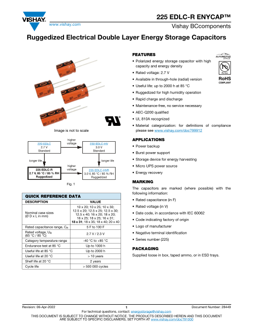
Image is not to scale please see www.vishay.com/doc?99912
higher APPLICATIONS
220 EDLC voltage 230 EDLC-HV
2.7 V 3.0 V • Power backup
Standard Standard
• Burst power support
longer life longer life • Storage device for energy harvesting
higher • Micro UPS power source
225 EDLC-R voltage 235 EDLC-HVR
2.7 V, 85 °C / 85 % RH 3.0 V, 85 °C / 85 % RH • Energy recovery
Ruggedized Ruggedized
MARKING
Fig. 1
The capacitors are marked (where possible) with th e
following information:
QUICK REFERENCE DATA
DESCRIPTION VALUE • Rated capacitance (in F)
10 x 20; 10 x 25; 10 x 30; • Rated voltage (in V)
12.5 x 20; 12.5 x 25; 12.5 x 30;
Nominal case sizes
(Ø D x L in mm) 12.5 x 40; 16 x 20; 18 x 20; • Date code, in accordance with IEC 60062
16 x 25; 18 x 25; 16 x 31; • Code indicating factory of origin
18 x 31; 18 x 35; 18 x 40; 20 x 40
Rated capacitance range, CR 5 F to 100 F • Logo of manufacturer
Rated voltage, UR 2.7 V / 2.3 V • Negative terminal identification
(65 °C / 85 °C)
Category temperature range -40 °C to +85 °C • Series number (225)
Endurance test at 85 °C Up to 1000 h
PACKAGING
Useful life at 85 °C Up to 2000 h
Useful life at 20 °C > 10 years Supplied loose in box, taped ammo, or in ESD trays.
Shelf life at 20 °C 2 years
Cycle life > 500 000 cycles
Revision: 06-Apr-2022 1 Document Number: 28449
For technical questions, contact: energystorage@vishay.com
THIS DOCUMENT IS SUBJECT TO CHANGE WITHOUT NOTICE. THE PRODUCTS DESCRIBED HEREIN AND THIS DOCUMENT
ARE SUBJECT TO SPECIFIC DISCLAIMERS, SET FORTH AT www.vishay.com/doc?91000
Page2
225 EDLC-R ENYCAP™
www.vishay.com Vishay BCcomponents
SELECTION CHART FOR CR, UR, AND RELEVANT NOMINAL CASE SIZES (Ø D x L in mm)
CR (F) UR (V) = 2.7 V
5 10 x 20
7 10 x 25
8 12.5 x 20
10 10 x 30
12 12.5 x 25
15 12.5 x 30
20 16 x 20
22 12.5 x 40
25 16 x 25; 18 x 20
30 18 x 25
35 16 x 31
40 18 x 31 (1)
50 18 x 35
60 18 x 40
100 20 x 40
Note
(1) Preferred case size
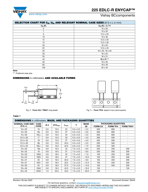
DIMENSIONS in millimeters AND AVAILABLE FORMS
L
Ø d
F Ø D
5 15
min. min.
Fig. 2 - Form CA / TRAY: long leads Fig. 3 - Form TFA: taped in box (ammopack)
Table 1
DIMENSIONS in millimeters, MASS, AND PACKAGING QUANTITIES
NOMINAL CASE SIZE CASE Ø d Ø D L F MASS PACKAGING QUANTITIES
Ø D x L CODE max. max. (g) FORM CA FORM TFA FORM TRAY
10 x 20 16 0.6 10.5 22 5.0 ± 0.5 ≈ 2.2 500 800 -
10 x 25 16L 0.6 10.5 27 5.0 ± 0.5 ≈ 3.0 500 800 -
10 x 30 16LL 0.8 10.5 32 5.0 ± 0.5 ≈ 3.5 500 800 -
12.5 x 20 17 0.6 13.0 22 5.0 ± 0.5 ≈ 4.0 500 500 -
12.5 x 25 18 0.6 13.0 27 5.0 ± 0.5 ≈ 5.0 250 500 -
12.5 x 30 18L 0.8 13.0 33.5 5.0 ± 0.5 ≈ 5.5 250 500 -
12.5 x 40 18LL 0.8 13.0 42.5 5.0 ± 0.5 ≈ 7.0 250 500 -
16 x 20 19a 0.8 16.5 22 7.5 ± 0.5 ≈ 6.0 250 250 200
16 x 25 19 0.8 16.5 27 7.5 ± 0.5 ≈ 8.0 250 250 200
18 x 20 1820 0.8 18.5 22 7.5 ± 0.5 ≈ 7.0 100 250 200
18 x 25 1825 0.8 18.5 27 7.5 ± 0.5 ≈ 10.0 100 250 200
16 x 31 20 0.8 16.5 33.5 7.5 ± 0.5 ≈ 9.0 100 250 200
18 x 31 1831 0.8 18.5 33.5 7.5 ± 0.5 ≈ 12.5 100 250 200
18 x 35 22 0.8 18.5 37.5 7.5 ± 0.5 ≈ 14.5 100 250 200
18 x 40 1840 0.8 18.5 42.5 7.5 ± 0.5 ≈ 16.5 100 - 150
20 x 40 2040 1.0 20.5 43.5 7.5 ± 0.5 ≈ 20.0 100 - -
Revision: 06-Apr-2022 2 Document Number: 28449
For technical questions, contact: energystorage@vishay.com
THIS DOCUMENT IS SUBJECT TO CHANGE WITHOUT NOTICE. THE PRODUCTS DESCRIBED HEREIN AND THIS DOCUMENT
ARE SUBJECT TO SPECIFIC DISCLAIMERS, SET FORTH AT www.vishay.com/doc?91000
Page3
225 EDLC-R ENYCAP™
www.vishay.com Vishay BCcomponents
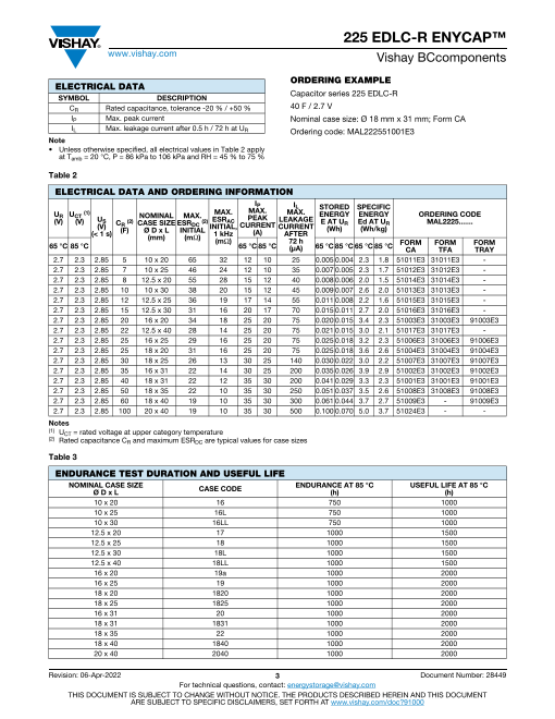
ORDERING EXAMPLE
ELECTRICAL DATA
SYMBOL DESCRIPTION Capacitor series 225 EDLC-R
CR Rated capacitance, tolerance -20 % / +50 % 40 F / 2.7 V
IP Max. peak current Nominal case size: Ø 18 mm x 31 mm; Form CA
IL Max. leakage current after 0.5 h / 72 h at UR Ordering code: MAL222551001E3
Note
• Unless otherwise specified, all electrical values in Table 2 appl y
at Tamb = 20 °C, P = 86 kPa to 106 kPa and RH = 45 % to 75 %
Table 2
ELECTRICAL DATA AND ORDERING INFORMATION
IP IL
U (1) MAX. MAX. STORED SPECIFIC
MAX.
R UCT
U NOMINAL MAX. PEAK ENERGY ENERGY ORDERING CODE
(V) (V) S C (2)
(V) R CASE SIZE ESR (2) ESRAC LEAKAGE
DC CURRENT E AT UR Ed AT UR MAL2225.......
INITIAL, CURRENT (Wh) (Wh/kg)
(< 1 s) (F) Ø D x L INITIAL (A)
(mm) (mΩ) 1 kHz AFTER
(mΩ) 72 h
65 °C 85 °C 65 °C 85 °C (μA) 65 °C 85 °C 65 °C 85 °C FORM FORM FORM
CA TFA TRAY
2.7 2.3 2.85 5 10 x 20 65 32 12 10 25 0.005 0.004 2.3 1.8 51011E3 31011E3 -
2.7 2.3 2.85 7 10 x 25 46 24 12 10 35 0.007 0.005 2.3 1.7 51012E3 31012E3 -
2.7 2.3 2.85 8 12.5 x 20 55 28 15 12 40 0.008 0.006 2.0 1.5 51014E3 31014E3 -
2.7 2.3 2.85 10 10 x 30 38 20 15 12 45 0.009 0.007 2.6 2.0 51013E3 31013E3 -
2.7 2.3 2.85 12 12.5 x 25 36 19 17 14 55 0.011 0.008 2.2 1.6 51015E3 31015E3 -
2.7 2.3 2.85 15 12.5 x 30 31 16 20 17 70 0.015 0.011 2.7 2.0 51016E3 31016E3 -
2.7 2.3 2.85 20 16 x 20 34 18 25 20 75 0.020 0.015 3.4 2.3 51003E3 31003E3 91003E3
2.7 2.3 2.85 22 12.5 x 40 28 14 25 20 75 0.021 0.015 3.0 2.1 51017E3 31017E3 -
2.7 2.3 2.85 25 16 x 25 29 16 25 20 75 0.025 0.018 3.2 2.3 51006E3 31006E3 91006E3
2.7 2.3 2.85 25 18 x 20 31 16 25 20 75 0.025 0.018 3.6 2.6 51004E3 31004E3 91004E3
2.7 2.3 2.85 30 18 x 25 26 13 30 25 140 0.030 0.022 3.0 2.2 51007E3 31007E3 91007E3
2.7 2.3 2.85 35 16 x 31 22 14 30 25 200 0.035 0.026 3.9 2.9 51002E3 31002E3 91002E3
2.7 2.3 2.85 40 18 x 31 22 12 35 30 200 0.041 0.029 3.3 2.3 51001E3 31001E3 91001E3
2.7 2.3 2.85 50 18 x 35 22 10 35 30 250 0.051 0.037 3.5 2.6 51008E3 31008E3 91008E3
2.7 2.3 2.85 60 18 x 40 19 10 35 30 300 0.061 0.044 3.7 2.7 51009E3 - 91009E3
2.7 2.3 2.85 100 20 x 40 19 10 35 30 500 0.100 0.070 5.0 3.7 51024E3 - -
Notes
(1) UCT = rated voltage at upper category temperature
(2) Rated capacitance CR and maximum ESRDC are typical values for case sizes
Table 3
ENDURANCE TEST DURATION AND USEFUL LIFE
NOMINAL CASE SIZE CASE CODE ENDURANCE AT 85 °C USEFUL LIFE AT 85 °C
Ø D x L (h) (h)
10 x 20 16 750 1000
10 x 25 16L 750 1000
10 x 30 16LL 750 1000
12.5 x 20 17 1000 1500
12.5 x 25 18 1000 1500
12.5 x 30 18L 1000 1500
12.5 x 40 18LL 1000 1500
16 x 20 19a 1000 2000
16 x 25 19 1000 2000
18 x 20 1820 1000 2000
18 x 25 1825 1000 2000
16 x 31 20 1000 2000
18 x 31 1831 1000 2000
18 x 35 22 1000 2000
18 x 40 1840 1000 2000
20 x 40 2040 1000 2000
Revision: 06-Apr-2022 3 Document Number: 28449
For technical questions, contact: energystorage@vishay.com
THIS DOCUMENT IS SUBJECT TO CHANGE WITHOUT NOTICE. THE PRODUCTS DESCRIBED HEREIN AND THIS DOCUMENT
ARE SUBJECT TO SPECIFIC DISCLAIMERS, SET FORTH AT www.vishay.com/doc?91000
Page4
225 EDLC-R ENYCAP™
www.vishay.com Vishay BCcomponents
Table 4
RUGGEDIZED FOR HIGH HUMIDITY - BIASED HUMIDITY TESTING
PARAMETER PROCEDURE (AT RATED VOLTAGE) REQUIREMENTS
After loading the capacitor for the specified time at maximum
category temperature Tmax. = 85 °C and 85 % relative humidity,
Humidity (relative) 85 % and derated permissible maximum operating voltage U = 2.3 V,
following parameters are valid within a timeframe of 1000 h:
No visible damage
No leakage of electrolyte
Temperature 85 °C ΔC/C: within ± 30 % of minimum initial specified value
ESR: less than 3 x initial specified value
Leakage: less than initial specified value
TEST PROCEDURES AND REQUIREMENTS (1)
NAME OF TEST PROCEDURE
(quick reference)
Capacitance CR and ESRDC Measured by DC discharging method as described in “Measuring of Characteristics”. (2)
Non-repetitive current for maximum 1 s at specified operating temperature.
Maximum peak current Maximum operating voltage (refer to derating table) must not be exceeded.
Usually to be tested with constant current discharge from UR to 0.5 x UR.
Maximum current should not be used in normal operation and is only provided as reference value.
Leakage current I Measured at UR. Capacitor is charged to the rated voltage at 20 °C. Leakage current is the current at specified
L time that is required to keep the capacitor charged at the rated voltage.
After loading the capacitor for specified time at maximum category temperature Tmax. = 85 °C and derated
permissible maximum operating voltage U = 2.3 V, following parameters are valid within a timeframe of
1000 h:
Endurance Capacitance Within ± 30 % of minimum initial specified value
ESR Less than 3 x initial specified value
Leakage Within specified value
After loading the capacitor for specified time at maximum category temperature Tmax. = 85 °C and derated
permissible maximum operating voltage U = 2.3 V, following parameters are valid within a timeframe of
2000 h:
Useful life Capacitance Within ± 50 % of minimum initial specified value
ESR Less than 4 x initial specified value
Leakage Within specified value
After loading the capacitor of specified time at maximum category temperature Tmax. = 85 °C and without
charge and under 40 % RH, following parameters are valid within a timeframe of 1000 h:
Storage at upper Capacitance Within ± 30 % of minimum initial specified value
category temperature
ESR Less than 3 x initial specified value
Leakage Within specified value
Shelf life Stored uncharged at 20 °C.
Parameter within initial specification
Cycles at 20 °C between rated voltage and half of rated voltage UR with constant current and 1 s rest between
charge and discharge: > 500 000 cycles
Cycle life Capacitance Within ± 30 % of minimum initial specified value
ESR Less than 3 x initial specified value
E [Wh] = ½ x C x (UR)2 x 1/3600
Stored energy E,
specific energy Ed and Ev Ed [Wh/kg] = ½ x C x (U )2R x 1/3600 x 1/mass
Ev [Wh/L] = ½ x C x (U )2R x 1/3600 x 1/volume
Soldering Hand or wave soldering allowed. For details refer to soldering requirements for radial aluminum electrolytic
capacitors in supplementary document.
Cleaning For printed circuit board cleaning apply non-aggressive cleaning agents only.
For details refer to cleaning requirements for aluminum electrolytic capacitors in supplementary document.
Do not expose capacitors to
• temperatures outside specified range
Environmental conditions • high humidity atmospheres; except series 225 which is ruggedized for high humidity 85 °C and 85 % RH
• corrosive atmospheres, e.g. halogenides, sulphurous or nitrous gases, acid or alkaline solutions, etc.
• environments containing oil and grease
Notes
• General remark: temperatures to be measured at capacitor case
(1) Conditions: electrical measurements at 20 °C, unless otherwise specified
(2) Rated capacitance CR and ESRDC
Revision: 06-Apr-2022 4 Document Number: 28449
For technical questions, contact: energystorage@vishay.com
THIS DOCUMENT IS SUBJECT TO CHANGE WITHOUT NOTICE. THE PRODUCTS DESCRIBED HEREIN AND THIS DOCUMENT
ARE SUBJECT TO SPECIFIC DISCLAIMERS, SET FORTH AT www.vishay.com/doc?91000
Page5
225 EDLC-R ENYCAP™
www.vishay.com Vishay BCcomponents
MEASURING OF CHARACTERISTICS
CAPACITANCE (C) EQUIVALENT SERIES RESISTANCE (ESRDC)
Capacitance shall be measured by constant current - Constant current charge to UR
discharge method. - Constant voltage charge at UR
- Constant current charge with 10 mA/F to UR - Constant current discharge to 0.1 V
- Constant voltage charge at UR ΔU [V]
- Constant current discharge with 10 mA/F to 0.1 V ESRDC [Ω] = ---------3--- ---------
ID [A]
UR ESRDC Equivalent series resistance, in Ω
ΔU3 ΔUR Voltage drop at internal resistance, in V
U1
ID Absolute value of discharge current, in A
U2
30 min t1 t2 (s)
Fig. 4 - Voltage Diagram for Capacitance Measurement
Capacitance value CR is given by discharge current ID, tim e
t and rated voltage UR, according to the following equation:
ID [A] x (t2 [s] - t
C [F] = -------------------------------------------------1 [s])
R -------------
U1 [V] - U2 [V]
CR Rated capacitance, in F
UR Rated voltage, in V
U1 Starting voltage, 0.8 x UR in V
U2 Ending voltage, 0.4 x UR in V
ΔU3 Voltage drop at internal resistance, in V
t Time from start of discharge until voltage U1 is
1 reached, in s
t Time from start of discharge until voltage U2 is
2 reached, in s
ID Absolute value of discharge current, in A
Statements about product lifetime are based on calculations and internal testing. They should only be interpreted as estimations. Also due to external factors, th e
lifetime in the field application may deviate from the calculated lifetime. In general, nothing stated herein shall be construed as a guarantee of durability.
Revision: 06-Apr-2022 5 Document Number: 28449
For technical questions, contact: energystorage@vishay.com
THIS DOCUMENT IS SUBJECT TO CHANGE WITHOUT NOTICE. THE PRODUCTS DESCRIBED HEREIN AND THIS DOCUMENT
ARE SUBJECT TO SPECIFIC DISCLAIMERS, SET FORTH AT www.vishay.com/doc?91000
Page6
Legal Disclaimer Notice
www.vishay.com Vishay
Disclaimer
ALL PRODUCT, PRODUCT SPECIFICATIONS AND DATA ARE SUBJECT TO CHANGE WITHOUT NOTICE TO IMPROV E
RELIABILITY, FUNCTION OR DESIGN OR OTHERWISE.
Vishay Intertechnology, Inc., its affiliates, agents, and employees, and all persons acting on its or their behalf (collectively ,
“Vishay”), disclaim any and all liability for any errors, inaccuracies or incompleteness contained in any datasheet or in any other
disclosure relating to any product.
Vishay makes no warranty, representation or guarantee regarding the suitability of the products for any particular purpose o r
the continuing production of any product. To the maximum extent permitted by applicable law, Vishay disclaims (i) any and all
liability arising out of the application or use of any product, (ii) any and all liability, including without limitation special,
consequential or incidental damages, and (iii) any and all implied warranties, including warranties of fitness for particular
purpose, non-infringement and merchantability.
Statements regarding the suitability of products for certain types of applications are based on Vishay's knowledge of typical
requirements that are often placed on Vishay products in generic applications. Such statements are not binding statement s
about the suitability of products for a particular application. It is the customer's responsibility to validate that a particular produc t
with the properties described in the product specification is suitable for use in a particular application. Parameters provided in
datasheets and / or specifications may vary in different applications and performance may vary over time. All operatin g
parameters, including typical parameters, must be validated for each customer application by the customer's technical experts.
Product specifications do not expand or otherwise modify Vishay's terms and conditions of purchase, including but not limited
to the warranty expressed therein.
Hyperlinks included in this datasheet may direct users to third-party websites. These links are provided as a convenience and
for informational purposes only. Inclusion of these hyperlinks does not constitute an endorsement or an approval by Vishay of
any of the products, services or opinions of the corporation, organization or individual associated with the third-party website .
Vishay disclaims any and all liability and bears no responsibility for the accuracy, legality or content of the third-party website
or for that of subsequent links.
Except as expressly indicated in writing, Vishay products are not designed for use in medical, life-saving, or life-sustainin g
applications or for any other application in which the failure of the Vishay product could result in personal injury or death.
Customers using or selling Vishay products not expressly indicated for use in such applications do so at their own risk. Please
contact authorized Vishay personnel to obtain written terms and conditions regarding products designed for such applications.
No license, express or implied, by estoppel or otherwise, to any intellectual property rights is granted by this document or by
any conduct of Vishay. Product names and markings noted herein may be trademarks of their respective owners.
© 2022 VISHAY INTERTECHNOLOGY, INC. ALL RIGHTS RESERVED
Revision: 01-Jan-2022 1 Document Number: 91000