


LoRaWAN 868/915MHz
このカタログについて
| ドキュメント名 | 8911 WIRELESS ACCELEROMETER FOR PROOF OF CONCEPT |
|---|---|
| ドキュメント種別 | 製品カタログ |
| ファイルサイズ | 497.2Kb |
| 取り扱い企業 | マウザー・エレクトロニクス (この企業の取り扱いカタログ一覧) |
この企業の関連カタログ


このカタログの内容
Page1
8911 wireless accelerometer for proof of concept、LoRaWAN™ 868/915MHz
te.com
8911 WIRELESS
ACCELEROMETER FOR
PROOF OF CONCEPT
LoRaWAN™ 868/915MHz
SPECIFICATIONS
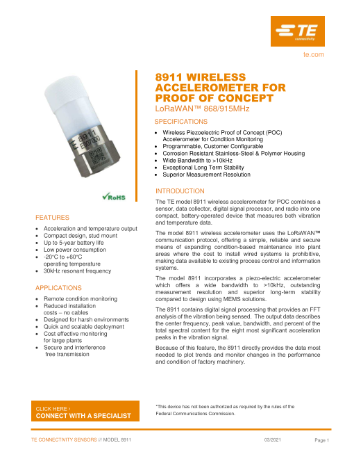
Wireless Piezoelectric Proof of Concept (POC)
Accelerometer for Condition Monitoring
Programmable, Customer Configurable
Corrosion Resistant Stainless-Steel & Polymer Housing
Wide Bandwdith to >10kHz
Exceptional Long Term Stability
Superior Measurement Resolution
INTRODUCTION
The TE model 8911 wireless accelerometer for POC combines a
sensor, data collector, digital signal processor, and radio into one
FEATURES compact, battery-operated device that measures both vibration
and temperature data.
Acceleration and temperature output
Compact design, stud mount The model 8911 wireless accelerometer uses the LoRaWAN™
Up to 5-year battery life communication protocol, offering a simple, reliable and secure
Low power consumption means of expanding condition-based maintenance into plant
areas where the cost to install wired systems is prohibitive,
-20°C to +60°C
making data available to existing process control and information
operating temperature
systems.
30kHz resonant frequency
The model 8911 incorporates a piezo-electric accelerometer
APPLICATIONS which offers a wide bandwidth to >10kHz, outstanding
measurement resolution and superior long-term stability
Remote condition monitoring compared to design using MEMS solutions.
Reduced installation
– The 8911 contains digital signal processing that provides an FFT
costs no cables analysis of the vibration being sensed. The output data describes
Designed for harsh environments the center frequency, peak value, bandwidth, and percent of the
Quick and scalable deployment total spectral content for the eight most significant acceleration
Cost effective monitoring peaks in the vibration signal.
for large plants
Secure and interference Because of this feature, the 8911 directly provides the data most
free transmission needed to plot trends and monitor changes in the performance
and condition of factory machinery.
CLICK HERE › *This device has not been authorized as required by the rules of the
CONNECT WITH A SPECIALIST Federal Communications Commission.
TE CONNECTIVITY SENSORS /// MODEL 8911 03/2021 Page 1
Page2
8911 WIRELESS ACCELEROMETER FOR PROOF OF CONCEPT
LoRaWAN™ 868/915MHz
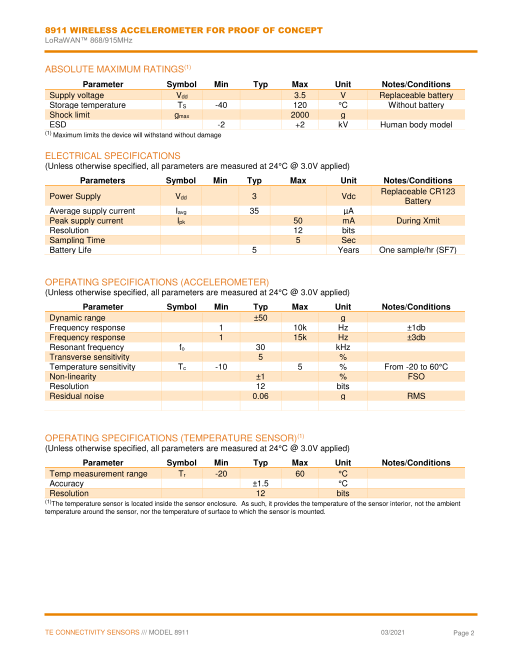
ABSOLUTE MAXIMUM RATINGS(1)
Parameter Symbol Min Typ Max Unit Notes/Conditions
Supply voltage Vdd 3.5 V Replaceable battery
Storage temperature TS -40 120 °C Without battery
Shock limit gmax 2000 g
ESD -2 +2 kV Human body model
(1) Maximum limits the device will withstand without damage
ELECTRICAL SPECIFICATIONS
(Unless otherwise specified, all parameters are measured at 24°C @ 3.0V applied)
Parameters Symbol Min Typ Max Unit Notes/Conditions
Replaceable CR123
Power Supply Vdd 3 Vdc
Battery
Average supply current Iavg 35 µA
Peak supply current Ipk 50 mA During Xmit
Resolution 12 bits
Sampling Time 5 Sec
Battery Life 5 Years One sample/hr (SF7)
OPERATING SPECIFICATIONS (ACCELEROMETER)
(Unless otherwise specified, all parameters are measured at 24°C @ 3.0V applied)
Parameter Symbol Min Typ Max Unit Notes/Conditions
Dynamic range ±50 g
Frequency response 1 10k Hz ±1db
Frequency response 1 15k Hz ±3db
Resonant frequency fo 30 kHz
Transverse sensitivity 5 %
Temperature sensitivity Tc -10 5 % From -20 to 60°C
Non-linearity ±1 % FSO
Resolution 12 bits
Residual noise 0.06 g RMS
OPERATING SPECIFICATIONS (TEMPERATURE SENSOR)(1)
(Unless otherwise specified, all parameters are measured at 24°C @ 3.0V applied)
Parameter Symbol Min Typ Max Unit Notes/Conditions
Temp measurement range Tr -20 60 °C
Accuracy ±1.5 °C
Resolution 12 bits
(1)The temperature sensor is located inside the sensor enclosure. As such, it provides the temperature of the sensor interior, not the ambient
temperature around the sensor, nor the temperature of surface to which the sensor is mounted.
TE CONNECTIVITY SENSORS /// MODEL 8911 03/2021 Page 2
Page3
8911 WIRELESS ACCELEROMETER FOR PROOF OF CONCEPT
LoRaWAN™ 868/915MHz
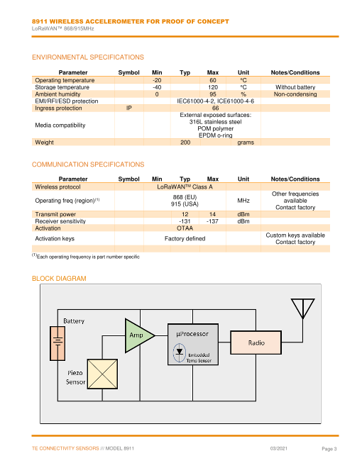
ENVIRONMENTAL SPECIFICATIONS
Parameter Symbol Min Typ Max Unit Notes/Conditions
Operating temperature -20 60 °C
Storage temperature -40 120 °C Without battery
Ambient humidity 0 95 % Non-condensing
EMI/RFI/ESD protection IEC61000-4-2, ICE61000-4-6
Ingress protection IP 66
External exposed surfaces:
316L stainless steel
Media compatibility
POM polymer
EPDM o-ring
Weight 200 grams
COMMUNICATION SPECIFICATIONS
Parameter Symbol Min Typ Max Unit Notes/Conditions
Wireless protocol LoRaWANTM Class A
Other frequencies
868 (EU)
Operating freq (region)(1) MHz available
915 (USA)
Contact factory
Transmit power 12 14 dBm
Receiver sensitivity -131 -137 dBm
Activation OTAA
Custom keys available
Activation keys Factory defined
Contact factory
(1)Each operating frequency is part number specific
BLOCK DIAGRAM
TE CONNECTIVITY SENSORS /// MODEL 8911 03/2021 Page 3
Page4
8911 WIRELESS ACCELEROMETER FOR PROOF OF CONCEPT
LoRaWAN™ 868/915MHz
TYPICAL ACCELEROMETER FREQUENCY RESPONSE CURVE
TYPICAL TEMPERATURE RESPONSE CURVE
TE CONNECTIVITY SENSORS /// MODEL 8911 03/2021 Page 4
Page5
8911 WIRELESS ACCELEROMETER FOR PROOF OF CONCEPT
LoRaWAN™ 868/915MHz
DIMENSIONS
TE CONNECTIVITY SENSORS /// MODEL 8911 03/2021 Page 5
Page6
8911 WIRELESS ACCELEROMETER FOR PROOF OF CONCEPT
LoRaWAN™ 868/915MHz
MOUNTING CONSIDERATIONS AND ACCESSORIES
A solid mounting method is required to get optimum performance from the accelerometer. Any loose parts or
unsecured mounting features will introduce noise and corrupt the signals of interest. Shown below are six
different mounting options available for the 8911 accelerometer for proof of concept.
¼-28 UNF-2A THD
1/4-28:1/4-28 Male Stud
1/4-28 UNF Female THD P/N AC-D03636
(Integrated part of the sensor)
¼-28 UNF-2A THD
¼-28 UNF-2A THD
M6 x 1.0-6g THD
Adhesive Mounting Stud
1/4-28:M6 Male Stud
P/N AC-D04210
P/N AC-D03665
¼-28 UNF-2A THD
¼-28 UNF-2A THD
M5 x 0.8-6g THD
Keeper (removeable) 1/4-28:M5 Male Stud
Magnetic Mounting Stud P/N AC-D03664
P/N AC-A04209
For the adhesive mounting stud, secure with a rigid adhesive such as epoxy or cyanoacrylate. Do not use
pressure sensitive adhesives or foam tapes. For the magnetic mounting stud, remove the keeper prior to
attachment. The magnetic mounting will have a 30 lb pull strength when attached to a ferrous surface.
TE CONNECTIVITY SENSORS /// MODEL 8911 03/2021 Page 6
Page7
8911 WIRELESS ACCELEROMETER FOR PROOF OF CONCEPT
LoRaWAN™ 868/915MHz
LoRaWAN™ Uplink Payload
0 1 2 3 4 5 6 7 8 9 10 11 12 13
Battery n Temperature Total Energy Integration Peak 1 Peak 1 Peak 1 Peak 2
Peaks (LSB First) (LSB First) Size Frequency Magnitude Ratio …
Detected (LSB First) (LSB first) (LSB first)
- Frequency, Magnitude, Ratio pattern will repeat n times, once for each peak.
- Total Energy is the total energy (integrated over the whole FFT)
- Integration Size is the size of the integration around the peak. For each peak detected, the embedded algorithm will integrate over a range
around the peak to measure the relative energy around this peak, and will also have the effect to disable detection of new peaks around
this detected peak
- Frequency is the center frequency of the peak detected
- Magnitude is the magnitude value of the peak detected
- Ratio is the locally integrated (over ‘Integration Size’ Hz) around this peak compared to the total energy
Data conversion:
Parameter Range Resolution Offset Hex Data Range Error code
Battery (%) 0 - 100 1% / bit 0% 0x00 to 0x64 0xFF
Temperature (°C) -20 to 60°C 0.1°C / bit -100°C 0x0050 to 0x00A0 0xFFFF
Total Energy (g) 0 - 40 0.001g / bit 0g 0x0000 to 0x9C40 N/A
Integration Size (Hz) 0 - 18000 1Hz / bit 0Hz 0x0000 to 0x4650 N/A
Frequency (Hz) 0 - 18000 1Hz / bit 0Hz 0x0000 to 0x4650 N/A
Magnitude (g) 0 - 40 0.001g / bit 0g 0x0000 to 0x9C40 N/A
Ratio (%) 0 - 100 1% / bit 0% 0x00 to 0x64 N/A
- Custom payload configurations available upon request.
The number of peaks detected by the algorithm is currently fixed at 8. This leads to a minimum LoRaWAN™
payload size of 48bytes, preventing the SF12 to be used in the US 915 configuration. Consequently, even if the
network requests the device to use SF12, the device will use SF11 as the payload would not fit in the SF12 frame.
LoRaWAN™ Configuration Downlink Payload
The device sampling period can be adjusted by sending a downlink LoRaWAN™ frame in the following format:
0 1 2 3 4
0x02 Sampling period in minutes (MSB first)
Minimum sampling period is 1-minute, maximum period is 1440 seconds (24 hours)
Example of a measurement interval set to 20min: 0200000014
TE CONNECTIVITY SENSORS /// MODEL 8911 03/2021 Page 7
Page8
8911 WIRELESS ACCELEROMETER FOR PROOF OF CONCEPT
LoRaWAN™ 868/915MHz
WORKFLOW
When the sensor powers up it performs a self-diagnostic then tries to join the LoRaWAN™ network using OTAA.
The sensor tries to join the network every 10 second and increases the join timer at every failed attempt by 20%,
up to 1 hour maximum. After a successful join the sensor enters sampling mode.
Once a LoRaWAN™ network has been joined, the sensor will loop through this workflow with a user defined period.
If the LoRaWAN™ transmission fails too many times the sensor will consider it has left the LoRaWAN™ network
and will go back to joining a network.
- Pressing the push button on the sensor at any point during the sensor’s life cycle will automatically trigger a new capture and data analysis.
BATTERY LIFE
The Sensor battery life will greatly depend on LoRa® spread factor (SF), therefore on sensor proximity from a
gateway and network quality.
Theorical lifetime
10
8
6
4
2
0
0 2 4 6 8 10 12 14 16 18 20 22 24
Transmission period (hours)
SF11 SF9 SF7
TE CONNECTIVITY SENSORS /// MODEL 8911 03/2021 Page 8
Lifetime (year)
Page9
8911 WIRELESS ACCELEROMETER FOR PROOF OF CONCEPT
LoRaWAN™ 868/915MHz
USING AND DISPLAYING DATA FROM THE SENSOR
The sensor vibration data in its FFT format can be used to construct visual displays and tables that provide
significant information regarding the operation and health of the machinery to which it’s attached. Examples are
shown below:
Raw Data:
Basic Data Table:
Peak Frequency (Hz) Amplitude of Peak % of Total Spectral
Energy
2056 168 23
2882 46 10
694 25 5
8 23 3
4122 20 5
5994 15 2
3805 12 4
1713 10 2
Total Energy 2.605g
FFT Visual Display:
TE CONNECTIVITY SENSORS /// MODEL 8911 03/2021 Page 9
Page10
8911 WIRELESS ACCELEROMETER FOR PROOF OF CONCEPT
LoRaWAN™ 868/915MHz
CONTROLS AND INDICATORS
The sensor has a single push button and 2 LEDs that indicate its status, one blue and one red.
Pressing the push button on the sensor at any point during the sensor’s life cycle will automatically trigger
a new capture and data analysis. This is useful when setting up the sensor in an application. No waiting
for a data capture from the normal cycle.
Blue LED:
- will light-up for two seconds when sensor requests to join LoRaWAN™ network, and receives join
acceptation
- will light-up shortly when sensor samples data, transmits LoRaWAN™ payload, receives
acknowledgement
Red LED:
- will light-up for two seconds if the LoRaWAN™ network join request is not accepted
- will light-up short shortly if a transmitted LoRaWAN™ payload is not acknowledged
Illumination of the colored LEDs can be seen through the translucent cover when it’s attached.
To gain access to the push-button and indicator LEDs, simply unscrew the top portion of the sensor housing
and locate these components on the PC board. See image below.
TE CONNECTIVITY SENSORS /// MODEL 8911 03/2021 Page 10
Page11
8911 WIRELESS ACCELEROMETER FOR PROOF OF CONCEPT
LoRaWAN™ 868/915MHz
ORDERING INFORMATION
8911-x
Part Number Part Description Tx/Rx Frequency
20011588-00 8911-A Wireless Accel for POC 915 MHz (USA)
20008458-00 8911-E Wireless Accel for POC 868 MHz (EMEA)
Mounting Accessories
Part Number Description
AC-D04210 Adhesive Mounting Stud
AC-A04209 Magnetic Mounting Stud
AC-D03636 ¼ x 28 by ¼ x 28 Double-ended Male Stud
AC-D03665 ¼ x 28 by M6 Double-ended Male Stud
AD-D03664 ¼ x 28 by M5 Double-ended Male Stud
Note – Unit is shipped without a battery. Batteries are available from any of our distribution partners or at most
retail locations that sell batteries.
*This device has not been authorized as required by the rules of the Federal Communications Commission.
CLICK HERE ›
CONNECT WITH A SPECIALIST
NORTH AMERICA EUROPE ASIA
Tel +1 800 522 6752 Tel +31 73 624 6999 Tel +86 0400 820 6015
te.com/sensors
TE Connectivity, TE, TE Connectivity (logo) and Every Connection Counts are trademarks. All other logos, products and/or company names referred to herein might be
trademarks of their respective owners
The information given herein, including drawings, illustrations and schematics which are intended for illustration purposes only, is believed to be reliable. However, TE
Connectivity makes no warranties as to its accuracy or completeness and disclaims any liability in connection with its use. TE Connectivity‘s obligations shall only be as
set forth in TE Connectivity‘s Standard Terms and Conditions of Sale for this product and in no case will TE Connectivity be liable for any incidental, indirect or
consequential damages arising out of the sale, resale, use or misuse of the product. Users of TE Connectivity products should make their own evaluation to determine
the suitability of each such product for the specific application.
© 2021 TE Connectivity Corporation. All Rights Reserved.
03/2021
TE CONNECTIVITY SENSORS /// MODEL 8911 03/2021 Page 11