


ThermaWick Thermal Jumper Surface Mount Chip
このカタログについて
| ドキュメント名 | Vishay Dale Thin Film THJP |
|---|---|
| ドキュメント種別 | 製品カタログ |
| ファイルサイズ | 157.6Kb |
| 取り扱い企業 | マウザー・エレクトロニクス (この企業の取り扱いカタログ一覧) |
この企業の関連カタログ


このカタログの内容
Page1
THJP
www.vishay.com Vishay Dale Thin Film
ThermaWickTM Thermal Jumper Surface Mount Chip
FEATURES
• Electrically isolated thermal conductor
• High thermal conductivity AlN substrate Available
(170 W/mK)
Available
• Electrically isolated terminations (> 999 MΩ)
• Low capacitance
• Available with SnPb or lead (Pb)-free wra p
terminations Available
• Material categorization: for definitions of complianc e
please see www.vishay.com/doc?99912
LINKS TO ADDITIONAL RESOURCES
3D 3 APPLICATIONS
D
3D Models Infographics • Power supplies and converters
THJP surface mount chips are designed to provide an • RF amplifiers
electrically isolated thermal conductive pathway to a groun d • Synthesizers
plane or heat sink while maintaining the electrical isolation of
the device. The devices are constructed with aluminum • Switch mode power supplies
nitride substrates in both SnPb and Pb-free wraparound • Pin and laser diodes
termination styles. The low capacitance of the device make s
them an excellent choice for high frequency and thermal • Filters
ladder applications. Custom sizes available.
FUNCTIONAL APPLICATIONS /
CONSTRUCTION CONNECTION OPTIONS
Solder coating • Component to heat sink
• Component to case
• Component to ground plane
Nickel termination
• Pad to pad
• Pad to via
Aluminum nitride
substrate • Pad to trace
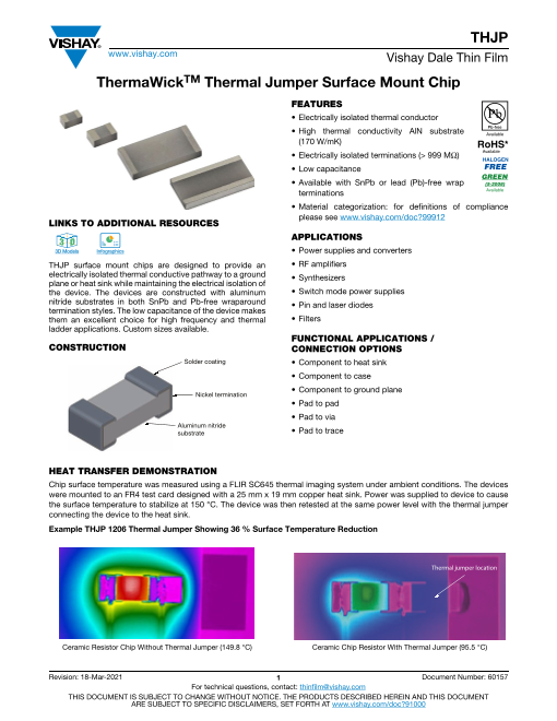
HEAT TRANSFER DEMONSTRATION
Chip surface temperature was measured using a FLIR SC645 thermal imaging system under ambient conditions. The devices
were mounted to an FR4 test card designed with a 25 mm x 19 mm copper heat sink. Power was supplied to device to caus e
the surface temperature to stabilize at 150 °C. The device was then retested at the same power level with the thermal jumpe r
connecting the device to the heat sink.
Example THJP 1206 Thermal Jumper Showing 36 % Surface Temperature Reduction
Thermal jumper location
Ceramic Resistor Chip Without Thermal Jumper (149.8 °C) Ceramic Chip Resistor With Thermal Jumper (95.5 °C)
Revision: 18-Mar-2021 1 Document Number: 60157
For technical questions, contact: thinfilm@vishay.com
THIS DOCUMENT IS SUBJECT TO CHANGE WITHOUT NOTICE. THE PRODUCTS DESCRIBED HEREIN AND THIS DOCUMENT
ARE SUBJECT TO SPECIFIC DISCLAIMERS, SET FORTH AT www.vishay.com/doc?91000
Page2
THJP
www.vishay.com Vishay Dale Thin Film
DIMENSIONS in inches
W
L
T
D
D
CASE SIZE L W T D
0603 0.061 ± 0.005 0.033 ± 0.005 0.030 ± 0.005 0.015 ± 0.005
0612 0.063 ± 0.005 0.126 ± 0.005 0.030 ± 0.005 0.015 ± 0.005
0805 0.079 ± 0.005 0.047 ± 0.005 0.030 ± 0.005 0.020 ± 0.005
1206 0.126 ± 0.005 0.063 ± 0.005 0.030 ± 0.005 0.020 ± 0.005
1225 0.126 ± 0.005 0.252 ± 0.005 0.030 ± 0.005 0.020 ± 0.005
2512 0.252 ± 0.005 0.126 ± 0.005 0.030 ± 0.005 0.020 ± 0.005
TYPICAL CHARACTERISTICS
CASE SIZE 0603 0612 0805 1206 1225 2512
Thermal resistance (°C/W), TR 14 4 13 15 4 15
Thermal conductance (mW/°C), TC 70 259 77 65 259 65
Capacitance (pF) 0.07 0.26 0.15 0.07 0.26 0.07
Dielectric withstanding voltage kVAC, RMS (60 Hz) > 1.5 > 1.5 > 1.5 > 1.5 > 1.5 > 1.5
Note
• TR = ------------L------------
k (T • W)
where k is the thermal conductivity of AIN, 170 W/mK
T = --1C ----
TR
STANDARD ELECTRICAL SPECIFICATIONS
TEST SPECIFICATIONS
Operating temperature range -65 °C to +150 °C
Storage temperature range -65 °C to +150 °C
STANDARD MATERIAL SPECIFICATIONS
Substrate material Aluminum nitride (170 W/mK)
Termination (tin / lead) Electroplate tin / lead over electroplate nickel
Termination (lead (Pb)-free) Electroplate tin (e3) over electroplate nickel
ENVIRONMENTAL TESTS (Vishay Performance vs. MIL-PRF-55342 / AEC-Q200 Requirements)
ENVIRONMENTAL TEST CONDITIONS LIMITS TYPICAL VISHAY
PERFORMANCE
Solderability Visual J-STD-002, method B and B1 95 % Acceptable
Solder mounting integrity Visual MIL-PRF-55342, method par. 4.8.13.1 Pass / fail Pass
Board flex Visual AEC-Q200, method 005 Pass / fail Pass
Revision: 18-Mar-2021 2 Document Number: 60157
For technical questions, contact: thinfilm@vishay.com
THIS DOCUMENT IS SUBJECT TO CHANGE WITHOUT NOTICE. THE PRODUCTS DESCRIBED HEREIN AND THIS DOCUMENT
ARE SUBJECT TO SPECIFIC DISCLAIMERS, SET FORTH AT www.vishay.com/doc?91000
Page3
THJP
www.vishay.com Vishay Dale Thin Film
GLOBAL PART NUMBER INFORMATION
New Global Part Numbering: THJP1206AST1
T H J P 1 2 0 6 A S T 1
GLOBAL MODEL CASE SIZE THICKNESS TERMINATION PACKAGING
THJP 0603 A = 0.030" B = wraparound Sn/Pb solder BS = BULK 100 min., 1 mult.
0805 with nickel termination
0612 S = wraparound Sn (e3) solder TAPE AND REEL
1206 with nickel termination T0 = 100 min., 100 mult.
1225 RoHS compliant T1 = 1000 min., 1000 mult.
2512 T3 = 300 min., 300 mult.
T5 = 500 min., 500 mult.
TF = full reel
TS = 100 min., 1 mult.
TI = 100 min., 1 mult.
(item single lot date code)
TP = 100 min., 1 mult.
(package unit single lot date code)
Revision: 18-Mar-2021 3 Document Number: 60157
For technical questions, contact: thinfilm@vishay.com
THIS DOCUMENT IS SUBJECT TO CHANGE WITHOUT NOTICE. THE PRODUCTS DESCRIBED HEREIN AND THIS DOCUMENT
ARE SUBJECT TO SPECIFIC DISCLAIMERS, SET FORTH AT www.vishay.com/doc?91000
Page4
Legal Disclaimer Notice
www.vishay.com Vishay
Disclaimer
ALL PRODUCT, PRODUCT SPECIFICATIONS AND DATA ARE SUBJECT TO CHANGE WITHOUT NOTICE TO IMPROV E
RELIABILITY, FUNCTION OR DESIGN OR OTHERWISE.
Vishay Intertechnology, Inc., its affiliates, agents, and employees, and all persons acting on its or their behalf (collectively ,
“Vishay”), disclaim any and all liability for any errors, inaccuracies or incompleteness contained in any datasheet or in any other
disclosure relating to any product.
Vishay makes no warranty, representation or guarantee regarding the suitability of the products for any particular purpose o r
the continuing production of any product. To the maximum extent permitted by applicable law, Vishay disclaims (i) any and all
liability arising out of the application or use of any product, (ii) any and all liability, including without limitation special,
consequential or incidental damages, and (iii) any and all implied warranties, including warranties of fitness for particular
purpose, non-infringement and merchantability.
Statements regarding the suitability of products for certain types of applications are based on Vishay's knowledge of typical
requirements that are often placed on Vishay products in generic applications. Such statements are not binding statement s
about the suitability of products for a particular application. It is the customer's responsibility to validate that a particular produc t
with the properties described in the product specification is suitable for use in a particular application. Parameters provided in
datasheets and / or specifications may vary in different applications and performance may vary over time. All operatin g
parameters, including typical parameters, must be validated for each customer application by the customer's technical experts.
Product specifications do not expand or otherwise modify Vishay's terms and conditions of purchase, including but not limited
to the warranty expressed therein.
Hyperlinks included in this datasheet may direct users to third-party websites. These links are provided as a convenience and
for informational purposes only. Inclusion of these hyperlinks does not constitute an endorsement or an approval by Vishay of
any of the products, services or opinions of the corporation, organization or individual associated with the third-party website .
Vishay disclaims any and all liability and bears no responsibility for the accuracy, legality or content of the third-party website
or for that of subsequent links.
Except as expressly indicated in writing, Vishay products are not designed for use in medical, life-saving, or life-sustainin g
applications or for any other application in which the failure of the Vishay product could result in personal injury or death.
Customers using or selling Vishay products not expressly indicated for use in such applications do so at their own risk. Please
contact authorized Vishay personnel to obtain written terms and conditions regarding products designed for such applications.
No license, express or implied, by estoppel or otherwise, to any intellectual property rights is granted by this document or by
any conduct of Vishay. Product names and markings noted herein may be trademarks of their respective owners.
© 2022 VISHAY INTERTECHNOLOGY, INC. ALL RIGHTS RESERVED
Revision: 01-Jan-2022 1 Document Number: 91000