


AWG NETBOX DN2.65x 16ビット、 40MS/s, 125MS/s、4,8,16チャネル
AWG NETBOX DN2.65x 16ビット、 40MS/s, 125MS/s、4,8,16チャネル
このカタログについて
| ドキュメント名 | AWG NETBOX DN2.65x 16ビット、 40MS/s, 125MS/s、4,8,16チャネル |
|---|---|
| ドキュメント種別 | 製品カタログ |
| ファイルサイズ | 990Kb |
| 登録カテゴリ | |
| 取り扱い企業 | 株式会社エレクトロニカ IMT事業部 (この企業の取り扱いカタログ一覧) |
この企業の関連カタログ


このカタログの内容
Page1
generatorNETBOX
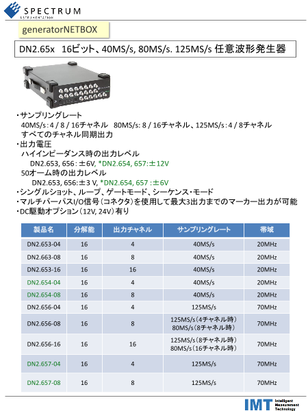
DN2.65x 16ビット、40MS/s, 80MS/s. 125MS/s 任意波形発生器
・サンプリングレート
40MS/s:4 / 8 / 16チャネル 80MS/s: 8 / 16チャネル、125MS/s:4 / 8チャネル
すべてのチャネル同期出力
・出力電圧
ハイインピーダンス時の出力レベル
DN2.653, 656:±6V, *DN2.654, 657:±12V
50オーム時の出力レベル
DN2.653, 656:±3 V, *DN2.654, 657 :±6V
・シングルショット、ループ、ゲートモード、シーケンス・モード
・マルチパーパスI/O信号(コネクタ)を使用して最大3出力までのマーカー出力が可能
・DC駆動オプション(12V, 24V)有り
製品名 分解能 出力チャネル サンプリングレート 帯域
DN2.653-04 16 4 40MS/s 20MHz
DN2.663-08 16 8 40MS/s 20MHz
DN2.653-16 16 16 40MS/s 20MHz
DN2.654-04 16 4 40MS/s 20MHz
DN2.654-08 16 8 40MS/s 20MHz
DN2.656-04 16 4 125MS/s 70MHz
125MS/s(4チャネル時)
DN2.656-08 16 8 70MHz
80MS/s(8チャネル時)
125MS/s(8チャネル時)
DN2.656-16 16 16 70MHz
80MS/s(16チャネル時)
DN2.657-04 16 4 125MS/s 70MHz
DN2.657-08 16 8 125MS/s 70MHz
Page2
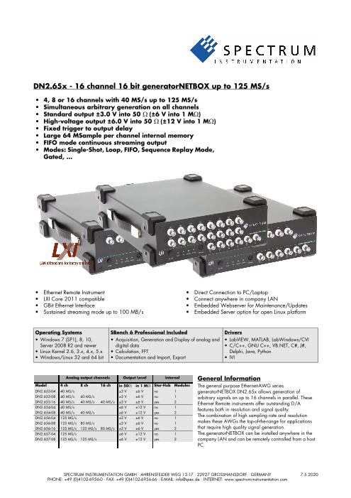
DN2.65x - 16 channel 16 bit generatorNETBOX up to 125 MS/s
• 4, 8 or 16 channels with 40 MS/s up to 125 MS/s
• Simultaneous arbitrary generation on all channels
• Standard output ±3.0 V into 50 Ω (±6 V into 1 MΩ)
• High-voltage output ±6.0 V into 50 Ω (±12 V into 1 MΩ)
• Fixed trigger to output delay
• Large 64 MSample per channel internal memory
• FIFO mode continuous streaming output
• Modes: Single-Shot, Loop, FIFO, Sequence Replay Mode,
Gated, ...
• Ethernet Remote Instrument • Direct Connection to PC/Laptop
• LXI Core 2011 compatible • Connect anywhere in company LAN
• GBit Ethernet Interface • Embedded Webserver for Maintenance/Updates
• Sustained streaming mode up to 100 MB/s • Embedded Server option for open Linux platform
Operating Systems SBench 6 Professional Included Drivers
• Windows 7 (SP1), 8, 10, • Acquisition, Generation and Display of analog and • LabVIEW, MATLAB, LabWindows/CVI
Server 2008 R2 and newer digital data • C/C++, GNU C++, VB.NET, C#, J#,
• Linux Kernel 2.6, 3.x, 4.x, 5.x • Calculation, FFT Delphi, Java, Python
• Windows/Linux 32 and 64 bit • Documentation and Import, Export • IVI
Analog output channels Output Level Internal General Information
Model 4 ch 8 ch 16 ch in 50Ω in 1 MΩ Star-Hub Modules The general purpose Ethernet-AWG series
DN2.653-04 40 MS/s ±3 V ±6 V no 1 generatorNETBOX DN2.65x allows generation of
DN2.653-08 40 MS/s 40 MS/s ±3 V ±6 V no 1 arbitrary signals on up to 16 channels in parallel. These
DN2.653-16 40 MS/s 40 MS/s 40 MS/s ±3 V ±6 V yes 2 Ethernet Remote instruments offer outstanding D/A
DN2.654-04 40 MS/s ±6 V ±12 V no 1 features both in resolution and signal quality.
DN2.654-08 40 MS/s 40 MS/s ±6 V ±12 V yes 2
DN2.656-04 125 MS/s ±3 V ±6 V no 1 The combination of high sampling rate and resolution
DN2.656-08 125 MS/s 80 MS/s ±3 V ±6 V no 1 makes these AWGs the top-of-the-range for applications
DN2.656-16 125 MS/s 125 MS/s 80 MS/s ±3 V ±6 V yes 2 that require high quality signal generation.
DN2.657-04 125 MS/s ±6 V ±12 V no 1 The generatorNETBOX can be installed anywhere in the
DN2.657-08 125 MS/s 125 MS/s ±6 V ±12 V yes 2 company LAN and can be remotely controlled from a host
PC.SPECTRUM INSTRUMENTATION GMBH · AHRENSFELDER WEG 13-17 · 22927 GROSSHANSDORF · GERMANY 7.5.2020
PHONE: +49 (0)4102-6956-0 · FAX: +49 (0)4102-6956-66 · E-MAIL: info@spec.de · INTERNET: www.spectrum-instrumentation.com
Page3
Software Support driver supports IVI Scope, IVI Digitizer and IVI FGen class with IVI-
C and IVI-COM interfaces.
Windows Support
The digitizerNETBOX/generatorNETBOX can be accessed from Third-party Software Products
Windows 7, Windows 8,Windows 10 (each 32 bit and 64 bit). Most popular third-party software products, such as LabVIEW,
Programming examples for Visual C++, C++ Builder, LabWin- MATLAB or LabWindows/CVI are supported. All drivers come
dows/CVI, Delphi, Visual Basic, VB.NET, C#, J#, Python, Java and with examples and detailed documentation.
IVI are included.
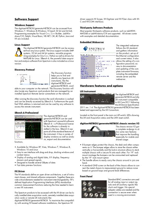
Embedded Webserver
Linux Support The integrated webserver
The digitizerNETBOX/generatorNETBOX can be access- follows the LXI standard
ed from any Linux system. The Linux support includes SMP and gathers information
systems, 32 bit and 64 bit systems, versatile program- on the product, set up of
ming examples for Gnu C++, Python as well as drivers for the Ethernet configuration
MATLAB for Linux. SBench 6, the powerful data acquisi- and current status. It also
tion and analysis software from Spectrum is also included as a Linux allows the setting of a con-
version. figuration password, ac-
cess to documentation
Discovery Protocol and updating of the com-
plete instrument firmware,
The Discovery function including the embedded
helps you to find and remote server and the
identify any Spectrum LXI webserver.
instruments, like the
digitizerNETBOX and
generatorNETBOX, avail- Hardware features and options
able to your computer on the network. The Discovery function will
also locate any Spectrum card products that are managed by an LXI Instrument
installed Spectrum Remote Server somewhere on the network. The digitizerNETBOX and
generatorNETBOX are fully
After running the discovery function the card information is cached LXI instrument compatible
and can be directly accessed by SBench 6. Furthermore the quali- to LXI Core 2011 following
fied VISA address is returned and can be used by any software to the LXI Device Specification
access the remote instrument. 2011 rev. 1.4. The digitizerNETBOX/generatorNETBOX has been
tested and approved by the LXI Consortium.
SBench 6 Professional
The digitizerNETBOX and Located on the front panel is the main on/off switch, LEDs showing
generatorNETBOX can be used the LXI and Acquisition status and the LAN reset switch.
with Spectrum’s powerful software
SBench 6 – a Professional license digitizerNETBOX/generatorNETBOX chassis version V2
for the software is already in- The chassis version V2 got
stalled in the box. SBench 6 sup- a complete re-design to al-
ports all of the standard features of low some new features
the instrument. It has a variety of that improve the handling
display windows as well as analy- especially for mobile and
sis, export and documentation shared usage:
functions.
• 8 bumper edges protect the chassis, the desk and other compo-
• Available for Windows XP, Vista, Windows 7, Windows 8, nents on it. The bumper edges allow to store the chassis either
Windows 10 and Linux vertically or horizontally and the lock-in structure allows to stack
• Easy to use interface with drag and drop, docking windows and multiple chassis with a secure fit onto each other. For 19“ rack
context menus mount montage the bumpers can be unmounted and replaced
• Display of analog and digital data, X-Y display, frequency by the 19“ rack mount option
domain and spread signals • The handle allows to easily carry the chassis around in juts one
• Designed to handle several GBytes of data hand.
• Fast data preview functions • A standard GND screw on the back of the chassis allows to con-
nect the metal chassis to measurement ground to reduce noise
IVI Driver based on ground loops and ground level differences.
The IVI standards define an open driver architecture, a set of instru-
ment classes, and shared software components. Together these pro- Front Panel
vide critical elements needed for instrument interchangeability. IVI's Standard BNC connectors are used
defined Application Programming Interfaces (APIs) standardize for all analog input or output sig-
common measurement functions reducing the time needed to learn nals and all auxiliary signals like
a new IVI instrument. clock and trigger. No special
adapter cables are needed and the
The Spectrum products to be accessed with the IVI driver can be lo- connection is secure even when
cally installed data acquisition cards, remotely installed data acqui- used in a moving environment.
sition cards or remote LXI instruments like
digitizerNETBOX/generatorNETBOX. To maximize the compatibil-
ity with existing IVI based software installations, the Spectrum IVI
Page4
Custom front panels are available on request even for small series, or until a stop command is executed. The trigger source can be ei-
be it SMA, LEMO connectors or custom specific connectors. ther one of the external trigger inputs or the software trigger. After
the first trigger additional trigger events will be ignored.
Ethernet Connectivity
The GBit Ethernet connection can be Single Restart replay
used with standard COTS Ethernet When this mode is activated the data of the on-board memory will
cabling. The integration into a stan- be replayed once after each trigger event. The trigger source can
dard LAN allows to connect the be either the external TTL trigger or software trigger.
digitizerNETBOX/generatorNET-
BOX either directly to a desktop PC FIFO mode
or Laptop or it is possible to place The FIFO mode is designed for continuous data transfer between
the instrument somewhere in the PC memory or hard disk and the generation board. The control of
company LAN and access it from any desktop over the LAN. the data stream is done automatically by the driver on an interrupt
request basis. The complete installed on-board memory is used for
DC Power Supply Option buffering data, making the continuous streaming extremely reliable.
The digitizerNETBOX/generatorNET-
BOX can be equipped with an internal Multiple Replay
DC power supply which replaces the The Multiple Replay mode al-
standard AC power supply. Two dif- lows the fast output genera-
ferent power supply options are avail- tion on several trigger events
able that range from 9V to 36V. without restarting the hard-
Contact the sales team if other DC lev- ware. With this option very
els are required. fast repetition rates can be
achieved. The on-board memory is divided into several segments of
Using the DC power supply the digitiz- the same size. Each segment can contain different data which will
erNETBOX/generatorNETBOX can be used for mobile applications then be played with the occurrence of each trigger event.
together with a Laptop in automotive or airborne applications.
Gated Replay
Boot on Power on Option
The Gated Sampling mode al-
The digitizerNETBOX/generatorNETBOX can be factory config- lows data replay controlled
ured to automatically start and boot upon availability of the input by an external gate signal.
power rail. That way the instrument will automatically become Data is only replayed if the
available again upon loss of input power. gate signal has attained a
programmed level.
Option Embedded Server
The option turns the digitizer- Sequence Mode
NETBOX/generatorNETBOX The sequence
in a powerful PC that allows to mode allows to
run own programs on a small split the card
and remote data acquisition memory into sev-
system. The digitizerNET- eral data segments of different length. These data segments are
BOX/generatorNETBOX is en- chained up in a user chosen order using an additional sequence
hanced by more memory, a powerful CPU, a freely accessable memory. In this sequence memory the number of loops for each seg-
internal SSD and a remote software development access method. ment can be programmed and trigger conditions can be defined to
proceed from segment to segment. Using the sequence mode it is
The digitizerNETBOX/generatorNETBOX can either run connected also possible to switch between replay waveforms by a simple soft-
to LAN or it can run totally independent, storing data to the internal ware command or to redefine waveform data for segments simulta-
SSD. The original digitizerNETBOX/generatorNETBOX remote in- neously while other segments are being replayed. All trigger-
strument functionality is still 100 % available. Running the embed- related and software-command-related functions are only working
ded server option it is possible to pre-calculate results based on the on single cards, not on star-hub-synchrnonized cards.
acquired data, store acquisitions locally and to transfer just the re-
quired data or results parts in a client-server based software struc-
ture. A different example for the External trigger input
digitizerNETBOX/generatorNETBOX embedded server is surveil- All boards can be triggered using up to two external analog or dig-
lance/logger application which can run totally independent for ital signals. One external trigger input has two analog comparators
days and send notification emails only over LAN or offloads stored that can define an edge or window trigger, a hysteresis trigger or
data as soon as it’s connected again. a rearm trigger. The other input has one comparator that can be
used for standard edge and level triggers.
Access to the embedded server is done through a standard text
based Linux shell based on the ssh secure shell. External clock input and output
Using a dedicated connector a sampling clock can be fed in from
Singleshot output an external system. Additionally it’s also possible to output the in-
When singleshot output is activated the data of the on-board mem- ternally used sampling clock on a separate connector to synchro-
ory is played exactly one time. The trigger source can be either one nize external equipment to this clock.
of the external trigger inputs or the software trigger. After the first
trigger additional trigger events will be ignored.
Repeated output
When the repeated output mode is used the data of the on-board
memory is played continuously for a programmed number of times
Page5
Reference clock
The option to use a precise
external reference clock
(normally 10 MHz) is nec-
essary to synchronize the
instrument for high-quality
measurements with external equipment (like a signal source). It’s
also possible to enhance the quality of the sampling clock in this
way. The driver automatically generates the requested sampling
clock from the fed in reference clock.
Page6
DN2 / DN6 Technical Data
Analog Outputs
Resolution 16 bit
D/A Interpolation no interpolation
Output amplitude software programmable 653x and 656x: ±1 mV up to ±3 V in 1 mV steps into 50 Ω termination
(resulting in ±2 mV up to ±6 V in 2mV steps into high impedance loads)
654x and 657x: ±1 mV up to ±6 V in 1 mV steps into 50 Ω termination
(resulting in ±2 mV up to ±12 V in 2mV steps into high impedance loads)
Note: Gain values below ±300 mV into 50 Ω are reduced by digital scaling of the samples
Output Amplifier Path Selection automatically by driver Low Power path: Selected Gain of ±1 mV to ±960 mV (into 50 Ω)
High Power path: 653x and 656x: Selected Gain of ±940 mV to ±3 V (into 50 Ω)
654x and 657x: Selected Gain of ±940 mV to ±6 V (into 50 Ω)
Output Amplifier Setting Hysteresis automatically by driver 940 mV to 960 mV (if output is using low power path it will switch to high power path at 960 mV. If
output is using high power path it will switch to low power path at 940 mV)
Output amplifier path switching time 1.2 ms (output disabled while switching)
Output offset software programmable Low Power path: ±960 mV in 1 mV steps into 50 Ω (±1920 mV in 2 mV steps into 1 MΩ)
High Power path: 653x and 656x: ±3 V in 1 mV steps into 50 Ω (±6V in 2 mV steps into 1 MΩ)
654x and 657x: ±6 V in 1 mV steps into 50 Ω (±12V in 2 mV steps into 1 MΩ)
Filters software programmable One of 4 different filters (refer to „Bandwidth and Filters“ section)
DAC Differential non linearity (DNL) DAC only ±2.0 LSB typical
DAC Integral non linearity (INL) DAC only ±4.0 LSB typical
Output resistance 50 Ω
Minimum output load 653x and 656x: 0 Ω (short circuit safe by design)
654x and 657x: 50 Ω (short circuit safe by hardware supervisor, outputs will turn off)
Max output swing in 50 Ω 653x and 656x: ±3.0 V (offset + amplitude)
654x and 657x: ±6.0 V (offset + amplitude)
Max output swing in 1 MΩ 653x and 656x: ±6.0 V (offset + amplitude)
654x and 657x: ±12.0 V (offset + amplitude)
Slewrate (using Filter 0) Low power path (0 to 900 mV): 250 mV/ns
653x and 656x: High power path (0 to 3000 mV): 850 mV/ns
654x and 657x: High power path (0 to 6000 mV): TBD
Crosstalk @ 1 MHz signal ±3 V 1 to 4 ch standard AWG 95 dB (M2p.6530, M2p.6531, M2p.6536, M2p.6560, M2p.6561, M2p.6566)
Crosstalk @ 1 MHz signal ±3 V 8 channel AWG 84 dB (M2p.6533, M2p.6568)
Crosstalk @ 1 MHz signal ±6 V 1 to 4 ch high-voltage AWG 99 dB (M2p.6540, M2p.6541, M2p.6546, M2p.6540, M2p.6541, M2p.6546)
Output accuracy ±1 mV ±0.5 % of programmed output amplitude ±0.1 % of programmed output offset
Trigger
Available trigger modes software programmable External, Software, Pulse, Or/And, Delay
Trigger edge software programmable Rising edge, falling edge or both edges
Trigger pulse width software programmable 0 to [4G - 1] samples in steps of 1 sample
Trigger delay software programmable 0 to [4G - 1] samples in steps of 1 samples
Trigger holdoff (for Multi, Gate) software programmable 0 to [4G - 1] samples in steps of 1 samples
Multi, Gate: re-arming time < 24 samples (+ programmed holdoff)
Trigger to Output Delay 63 sample clocks + 7 ns
Memory depth software programmable 16 up to [installed memory / number of active channels] samples in steps of 8
Multiple Replay segment size software programmable 8 up to [installed memory / number of active channels] samples in steps of 8
External trigger accuracy 1 sample
External trigger Ext X1, X2, X3
External trigger type Single level comparator 3.3V LVTTL logic inputs
External trigger impedance software programmable 50 Ω / 5 kΩ For electrical specifications refer to
External trigger input level ±5 V (5 kΩ), ±2.5 V (50 Ω), „Multi Purpose I/O lines“ section.
External trigger over voltage protection ±20 V (5 kΩ), 5 Vrms (50 Ω)
External trigger sensitivity 200 mVpp
(minimum required signal swing)
External trigger level software programmable ±5 V in steps of 1 mV
External trigger bandwidth 50 Ω DC to 400 MHz n.a.
5 kΩ DC to 300 MHz DC to 125 MHz
Minimum external trigger pulse width ≥ 2 samples ≥ 2 samples
Page7
Multi Purpose I/O lines
Number of multi purpose output lines one, named X0
Number of multi purpose input/output lines three, named X1, X2, X3
Multi Purpose line X0 X1, X2, X3
Input: available signal types software programmable n.a. Asynchronous Digital-In, Logic trigger
Input: signal levels n.a. 3.3 V LVTTL
Input: impedance n.a. 10 kΩ to 3.3 V
Input: maximum voltage level n.a. -0.5 V to +4.0 V
Input: maximum bandwidth n.a. 125 MHz
Output: available signal types software programmable Run-, Arm-, Trigger-Output, Run-, Arm-, Trigger-Output,
Marker-Output, Synchronous Digital-Out, Marker-Output, Synchronous Digital-Out,
Asynchronous Digital-Out Asynchronous Digital-Out,
ADC Clock Output,
Output: impedance 50 Ω
Output: drive strength Capable of driving 50 Ω loads, maximum drive strength ±48 mA
Output: type / signal levels 3.3V LVTTL, TTL compatible for high impedance loads
Output: update rate (synchronous modes) sampling clock
Sequence Replay Mode
Number of sequence steps software programmable 1 up to 4096 (sequence steps can be overloaded at runtime)
Number of memory segments software programmable 2 up to 64k (segment data can be overloaded at runtime)
Minimum segment size software programmable 32 samples in steps of 8 samples.
Maximum segment size software programmable 512 MS / active channels / number of sequence segments (round up to the next power of two)
Loop Count software programmable 1 to (1M - 1) loops
Sequence Step Commands software programmable Loop for #Loops, Next, Loop until Trigger, End Sequence
Special Commands software programmable Data Overload at runtime, sequence steps overload at runtime,
readout current replayed sequence step
Limitations for synchronized products Software commands changing the sequence as well as „Loop until trigger“ are not synchronized
between cards. This also applies to multiple AWG modules in a generatorNETBOX.
Clock
Clock Modes software programmable internal PLL, external clock, external reference clock, sync
Internal clock range (PLL mode) software programmable see „Clock Limitations“ table below
Internal clock accuracy after warm-up ≤ ±1.0 ppm (at time of calibration in production)
Internal clock aging ≤ ±0.5 ppm / year
PLL clock setup granularity (int. or ext. reference) 1 Hz
External reference clock range software programmable 128 kHz up to 125 MHz
Direct external clock to internal clock delay 4.3 ns
Direct external clock range see „Clock Limitations and Bandwidth“ table below
External clock type Single level comparator
External clock input level ±5 V (5 kΩ), ±2.5 V (50 Ω),
External clock input impedance software programmable 50 Ω / 5 kΩ
External clock over voltage protection ±20 V (5 kΩ), 5 Vrms (50 Ω)
External clock sensitivity 200 mVpp
(minimum required signal swing)
External clock level software programmable ±5 V in steps of 1mV
External clock edge rising edge used
External reference clock input duty cycle 45% - 55%
Clock output electrical specification Available via Multi Purpose output X0. Refer to „Multi Purpose I/O lines“ section.
Synchronization clock multiplier „N“ for software programmable N being a multiplier (1, 2, 3, 4, 5, ... Max) of the card with the currently slowest sampling clock.
different clocks on synchronized cards The card maximum (see „Clock Limitations and Bandwidth“ table below) must not be exceeded.
Channel to channel skew on one card < 200 ps (typical)
Skew between star-hub synchronized cards TBD
Clock Limitations
M2p.653x M2p.656x
DNx.653-xx DNx.656-xx
M2p.654x M2p.657x
DNx.654-xx DNx.657-xx
max internal clock (non-synchronized cards) 40 MS/s 125 MS/s
min internal clock (non-synchronized cards) 1 kS/s 1 kS/s
max internal clock (cards synchronized via star-hub) 40 MS/s 125 MS/s
min internal clock (cards synchronized via star-hub) 128 kS/s 128 kS/s
max direct external clock 40 MS/s 125 MS/s
min direct external clock DC DC
min direct external clock LOW time 4 ns 4 ns
min direct external clock HIGH time 4 ns 4 ns
Page8
Bandwidth and Filters
Filter - 3dB bandwidth Filter characteristic
Analog bandwidth does not include Sinc response of DAC Filter 0 70 MHz third-order Butterworth
Filter 1 20 MHz fifth-order Butterworth
Filter 2 5 MHz fourth-order Bessel
Filter 3 1 MHz fourth-order Bessel
Dynamic Parameters
M2p.653x/DNx.653-xx
Test - Samplerate 40 MS/s 40 MS/s
Output Frequency 800 kHz 4 MHz
Output Level in 50 Ω ±900mV ±3000mV ±900mV ±3000mV
Used Filter 1 MHz 5 MHz
NSD (typ) -142 dBm/Hz -132 dBm/Hz -142 dBm/Hz -132 dBm/Hz
SNR (typ) 90.7 dB 91.1 dB 83.7 dB 84.1 dB
THD (typ) -74.0 dB -74.0 dB -70.5 dB -70.5 dB
SINAD (typ) 73.9 dB 73.9 dB 69.8 dB 69.8 dB
SFDR (typ), excl harm. 97.0 dB 95.0 dB 88.0 dB 88.0 dB
ENOB (SINAD) 12.0 12.0 11.3 11.3
ENOB (SNR) 14.7 14.8 13.5 13.6
M2p.654x/DNx.654-xx
Test - Samplerate 40 MS/s 40 MS/s
Output Frequency 800 kHz 4 MHz
Output Level in 50 Ω ±900mV ±6000mV ±900mV ±6000mV
Used Filter 1 MHz 5 MHz
NSD (typ) -138 dBm/Hz -129 dBm/Hz -142 dBm/Hz -126 dBm/Hz
SNR (typ) 86.7 dB 88.1 dB 83.7 dB 84.2 dB
THD (typ) -74.0 dB -74.0 dB -74.0 dB -74.0 dB
SINAD (typ) 73.8 dB 73.8 dB 73.6 dB 73.6 dB
SFDR (typ), excl harm.
ENOB (SINAD) 12.0 12.0 11.9 11.9
ENOB (SNR) 14.1 14.3 13.6 13.7
M2p.656x/DNx.656-xx
Test - Samplerate 125 MS/s 125 MS/s 125 MS/s
Output Frequency 800 kHz 4 MHz 16 MHz
Used Filter 1 MHz 5 MHz 20 MHz
Output Level in 50 Ω ±900mV ±3000mV ±900mV ±3000mV ±900mV ±3000mV
NSD (typ) -142 dBm/Hz -132 dBm/Hz -142 dBm/Hz -132 dBm/Hz -142 dBm/Hz -132 dBm/Hz
SNR (typ) 90.7 dB 91.1 dB 83.7 dB 84.1 dB 77.7 dB 78.1 dB
THD (typ) -74.0 dB -74.0 dB -70.5 dB -70.5 dB -66.0 dB -61.9 dB
SINAD (typ) 73.9 dB 73.9 dB 69.8 dB 69.8 dB 65.7 dB 60.9 dB
SFDR (typ), excl harm. 97.0 dB 95.0 dB 88.0 dB 88.0 dB 90.0 dB 89.0 dB
ENOB (SINAD) 12.0 12.0 11.3 11.3 10.6 9.8
ENOB (SNR) 14.7 14.8 13.5 13.6 12.5 12.6
M2p.657x/DNx.657-xx
Test - Samplerate 125 MS/s 125 MS/s 125 MS/s
Output Frequency 800 kHz 4 MHz 16 MHz
Used Filter 1 MHz 5 MHz 20 MHz
Output Level in 50 Ω ±900mV ±6000mV ±900mV ±6000mV ±900mV ±6000mV
NSD (typ) -138 dBm/Hz -129 dBm/Hz -142 dBm/Hz -126 dBm/Hz -142 dBm/Hz -127 dBm/Hz
SNR (typ) 86.7 dB 88.1 dB 83.7 dB 84.2 dB 77.7 dB 79.1 dB
THD (typ) -74.0 dB -74.0 dB -74.0 dB -74.0 dB -70.5 dB -63.1 dB
SINAD (typ) 73.8 dB 73.8 dB 73.6 dB 73.6 dB 69.7 dB 63.0 dB
SFDR (typ), excl harm.
ENOB (SINAD) 12.0 12.0 11.9 11.9 11.3 10.2
ENOB (SNR) 14.1 14.3 13.6 13.7 12.6 12.8
THD and SFDR are measured at the given output level and 50 Ohm termination with a high resolution M3i.4860/M4i.4450-x8 data acquisition card and are calculated from the spec-
trum. Noise Spectral Density is measured with built-in calculation from an HP E4401B Spectrum Analyzer. All available D/A channels are activated for the tests. SNR and SFDR figures
may differ depending on the quality of the used PC. NSD = Noise Spectral Density, THD = Total Harmonic Distortion, SFDR = Spurious Free Dynamic Range.
Page9
DN2 specific Technical Data
Environmental and Physical Details DN2.xxx
Dimension of Chassis without connectors or bumpers L x W x H 366 mm x 267 mm x 87 mm
Dimension of Chassis with 19“ rack mount option L x W x H 366 mm x 482.6 mm x 87 mm (2U height)
Weight (1 internal acquisition/generation module) 6.3 kg, with rack mount kit: 6.8 kg
Weight (2 internal acquisition/generation modules) 6.7 kg, with rack mount kit 7.2 kg
Warm up time 20 minutes
Operating temperature 0°C to 40°C
Storage temperature -10°C to 70°C
Humidity 10% to 90%
Dimension of packing (single DN2) L x W x H 470 mm x 390 mm x 180 mm
Volume weight of Packing (single DN2) 7.0 kgs
Power Consumption
230 VAC 12 VDC 24 VDC
DN2.653-04, DN2.656-04 TBD TBD TBD TBD TBD TBD
DN2.653-08, DN2.656-08 TBD TBD TBD TBD TBD TBD
DN2.653-16, DN2.656-16 TBD TBD TBD TBD TBD TBD
DN2.654-04, DN2.657-04 TBD TBD TBD TBD TBD TBD
DN2.654-08, DN2.657-08 TBD TBD TBD TBD TBD TBD
MTBF
MTBF TBD
Page10
Block diagram of generatorNETBOX DN2
• The number of maximum channels and internal AWG modules and existance of a synchronization Star-Hub is model dependent.
Block diagram of generatorNETBOX module DN2.65x
Page11
Order Information
The generatorNETBOX is equipped with a large internal memory and supports standard replay, FIFO replay (streaming), Multiple Replay,
Gated Replay, Continuous Replay (Loop), Single-Restart as well as Sequence. Operating system drivers for Windows/Linux 32 bit and 64
bit, drivers and examples for C/C++, IVI (Function Generator class), LabVIEW (Windows), MATLAB (Windows and Linux), .NET, Delphi,
Java, Python and a Professional license of the oscilloscope software SBench 6 are included.
The system is delivered with a connection cable meeting your countries power connection. Additional power connections with other standards
are available as option.
generatorNETBOX DN2 - Ethernet/LXI Interface
Order no. Resolution Output Channels Memory Output@50Ω Output@1MΩ
DN2.653-04 16 Bit 4 channels 40 MS/s 1 x 512 MSamples ±3V ±6V
DN2.653-08 16 Bit 8 channels 40 MS/s 1 x 512 MSamples ±3V ±6V
DN2.653-16 16 Bit 16 channels 40 MS/s 2 x 512 MSamples ±3V ±6V
DN2.654-04 16 Bit 4 channels 40 MS/s 1 x 512 MSamples ±6V ±12V
DN2.654-08 16 Bit 8 channels 40 MS/s 2 x 512 MSamples ±6V ±12V
DN2.656-04 16 Bit 4 channels 125 MS/s 1 x 512 MSamples ±3V ±6V
DN2.656-08 16 Bit 4 channels 125 MS/s 1 x 512 MSamples ±3V ±6V
8 channels 80 MS/s
DN2.656-16 16 Bit 8 channels 125 MS/s 2 x 512 MSamples ±3V ±6V
16 channels 80 MS/s
DN2.657-04 16 Bit 4 channels 125 MS/s 1 x 512 MSamples ±6V ±12V
DN2.657-08 16 Bit 8 channels 125 MS/s 2 x 512 MSamples ±6V ±12V
Options
Order no. Option
DN2.xxx-Rack 19“ rack mounting set for self mounting
DN2.xxx-Emb Extension to Embedded Server: CPU, more memory, SSD. Access via remote Linux secure shell (ssh)
DN2.xxx-DC12 12 VDC internal power supply. Replaces AC power supply. Accepts 9 V to 18 V DC input. Screw terminals.
DN2.xxx-DC24 24 VDC internal power supply. Replaces AC power supply. Accepts 18 V to 36 V DC input. Screw terminals
DN2.xxx-BTPWR Boot on Power On: the digitizerNETBOX/generatorNETBOX automatically boots if power is switched on.
Calibration
Order no. Option
DN2.xxx-Recal Recalibration of complete digitizerNETBOX/generatorNETBOX DN2 including calibration protocol
BNC Cables
The standard adapter cables are based on RG174 cables and have a nominal attenuation of 0.3 dB/m at 100 MHz.
for Connections Connection Length to SMA male to SMA female to BNC male to SMB female
All BNC male 80 cm Cab-9m-3mA-80 Cab-9m-3fA-80 Cab-9m-9m-80 Cab-9m-3f-80
All BNC male 200 cm Cab-9m-3mA-200 Cab-9m-3fA-200 Cab-9m-9m-200 Cab-9m-3f-200
Technical changes and printing errors possible
SBench, digitizerNETBOX and generatorNETBOX are registered trademarks of Spectrum Instrumentation GmbH. Microsoft, Visual C++, Windows, Windows 98, Windows NT, Window 2000, Windows XP, Windows Vista,
Windows 7, Windows 8 and Windows 10 are trademarks/registered trademarks of Microsoft Corporation. LabVIEW, DASYLab, Diadem and LabWindows/CVI are trademarks/registered trademarks of National Instruments
Corporation. MATLAB is a trademark/registered trademark of The Mathworks, Inc. Delphi and C++Builder are trademarks/registered trademarks of Embarcadero Technologies, Inc. Keysight VEE, VEE Pro and VEE OneLab
are trademarks/registered trademarks of Keysight Technologies, Inc. FlexPro is a registered trademark of Weisang GmbH & Co. KG. PCIe, PCI Express and PCI-X and PCI-SIG are trademarks of PCI-SIG. LXI is a registered
trademark of the LXI Consortium. PICMG and CompactPCI are trademarks of the PCI Industrial Computation Manufacturers Group. Oracle and Java are registered trademarks of Oracle and/or its affiliates. Intel and Intel Core
i3, Core i5, Core i7, Core i9 and Xeon are trademarks and/or registered trademarks of Intel Corporation. AMD, Opteron, Sempron, Phenom, FX, Ryzen and EPYC are trademarks and/or registered trademarks of Advanced
Micro Devices. NVIDIA, CUDA, GeForce, Quadro and Tesla are trademarks/registered trademarks of NVIDIA Corporation.