


デジタイザNETBOX DN2.59x 16ビット、5MS/s, 20MS/s, 40MS/s, 80MS/s, 125MS/s、4~16チャネル
製品カタログ
デジタイザNETBOX DN2.59x 16ビット、5MS/s, 20MS/s, 40MS/s, 80MS/s, 125MS/s、4~16チャネル
デジタイザNETBOX DN2.59x 16ビット、5MS/s, 20MS/s, 40MS/s, 80MS/s, 125MS/s、4~16チャネル
このカタログについて
| ドキュメント名 | デジタイザNETBOX DN2.59x 16ビット、5MS/s, 20MS/s, 40MS/s, 80MS/s, 125MS/s、4~16チャネル |
|---|---|
| ドキュメント種別 | 製品カタログ |
| ファイルサイズ | 1.1Mb |
| 登録カテゴリ | |
| 取り扱い企業 | 株式会社エレクトロニカ IMT事業部 (この企業の取り扱いカタログ一覧) |
この企業の関連カタログ


このカタログの内容
Page1
degitizerNETBOX
DN2.59xx
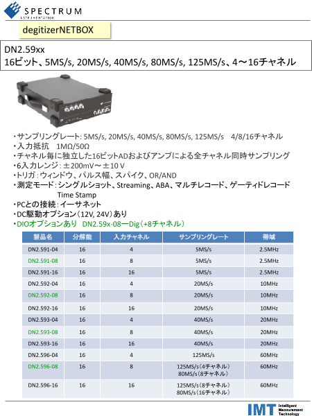
16ビット、5MS/s, 20MS/s, 40MS/s, 80MS/s, 125MS/s、4~16チャネル
・サンプリングレート: 5MS/s, 20MS/s, 40MS/s, 80MS/s, 125MS/s 4/8/16チャネル
・入力抵抗 1MΩ/50Ω
・チャネル毎に独立した16ビットADおよびアンプによる全チャネル同時サンプリング
・6入力レンジ:±200mV~±10 V
・トリガ:ウィンドウ、パルス幅、スパイク、OR/AND
・測定モード:シングルショット、Streaming、ABA、マルチレコード、ゲーティドレコード
Time Stamp
・PCとの接続:イーサネット
・DC駆動オプション(12V, 24V)あり
・DIOオプションあり DN2.59x-08ーDig(+8チャネル)
製品名 分解能 入力チャネル サンプリングレート 帯域
DN2.591-04 16 4 5MS/s 2.5MHz
DN2.591-08 16 8 5MS/s 2.5MHz
DN2.591-16 16 16 5MS/s 2.5MHz
DN2.592-04 16 4 20MS/s 10MHz
DN2.592-08 16 8 20MS/s 10MHz
DN2.592-16 16 16 20MS/s 10MHz
DN2.593-04 16 4 40MS/s 20MHz
DN2.593-08 16 8 40MS/s 20MHz
DN2.593-16 16 16 40MS/s 20MHz
DN2.596-04 16 4 125MS/s 60MHz
DN2.596-08 16 8 125MS/s(4チャネル) 60MHz
80MS/s(8チャネル)
DN2.596-16 16 16 125MS/s(8チャネル) 60MHz
80MS/s(16チャネル)
Page2
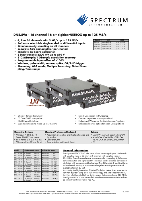
DN2.59x - 16 channel 16 bit digitizerNETBOX up to 125 MS/s
• 4, 8 or 16 channels with 5 MS/s up to 125 MS/s Speed SNR ENOB
• Software selectable single-ended or differential inputs 5 MS/s up to 86.0 dB up to 14.0 LSB20 MS/s up to 81.0 dB up to 13.2 LSB
• Simultaneously sampling on all channels 40 MS/s up to 75.3 dB up to 12.2 LSB
• Separate ADC and amplifier per channel 125 MS/s up to 73.3 dB up to 11.8 LSB
• complete on-board calibration
• 6 input ranges: ±200 mV up to ±10 V
• 512 MSample/1 GSample acquisition memory
• Programmable input offset of ±100%
• Window, pulse width, re-arm, spike, OR/AND trigger
• Streaming, ABA mode, Multiple Recording, Gated Sam-
pling, Timestamps
• Ethernet Remote Instrument • Direct Connection to PC/Laptop
• LXI Core 2011 compatible • Connect anywhere in company LAN
• GBit Ethernet Interface • Embedded Webserver for Maintenance/Updates
• Sustained streaming mode up to 70 MB/s • Embedded Server option for open Linux platform
Operating Systems SBench 6 Professional Included Drivers
• Windows 7 (SP1), 8, 10, • Acquisition, Generation and Display of analog and • LabVIEW, MATLAB, LabWindows/CVI
Server 2008 R2 and newer digital data • Visual C++, C++ Builder, GNU C++,
• Linux Kernel 2.6, 3.x, 4.x, 5.x • Calculation, FFT VB.NET, C#, J#, Delphi, Java, Python
• Windows/Linux 32 and 64 bit • Documentation and Import, Export • IVI
Model Single-Ended Inputs Differential Inputs General Information
DN2.591-04 4 channels 5 MS/s 4 channels 5 MS/s The digitizerNETBOX DN2.49x series allows recording of up to 16 channels
DN2.591-08 8 channels 5 MS/s 4 channels 5 MS/s with sampling rates of 80 MS/s or 8 channels with sampling rates of
DN2.591-16 16 channels 5 MS/s 8 channels 5 MS/s 125 MS/s. These Ethernet Remote instruments offer outstanding A/D features
DN2.592-04 4 channels 20 MS/s 4 channels 20 MS/s both in resolution and signal quality. The inputs can be switched between Sin-
DN2.592-08 8 channels 20 MS/s 4 channels 20 MS/s
DN2.592-16 16 channels 20 MS/s 8 channels 20 MS/s gle-Ended with a programmable offset and True Differential. If used in differen-
DN2.593-04 4 channels 40 MS/s 4 channels 40 MS/s tial mode each two inputs are connected together reducing the number of
DN2.593-08 8 channels 40 MS/s 4 channels 40 MS/s available channels by half.
DN2.593-16 16 channels 40 MS/s 8 channels 40 MS/s Importantly, the high-resolution 16-bit ADCs deliver sixteen times more resolu-
DN2.596-04 4 channels 125 MS/s 4 channels 125 MS/s tion than digitizers using older 12-bit technology and 256 times more resolu-
DN2.596-08 8 channels 80 MS/s 4 channels 125 MS/s tion than what is available from digital scopes that commonly use 8-bit ADCs.
4 channels 125 MS/s The digitizerNETBOX can be installed anywhere in the company LAN and can
DN2.596-16 16 channels 80 MS/s 8 channels 125 MS/s
8 channels 125 MS/s be remotely controlled from a host PC.SPECTRUM INSTRUMENTATION GMBH · AHRENSFELDER WEG 13-17 · 22927 GROSSHANSDORF · GERMANY 7.5.2020
PHONE: +49 (0)4102-6956-0 · FAX: +49 (0)4102-6956-66 · E-MAIL: info@spec.de · INTERNET: www.spectrum-instrumentation.com
Page3
Software Support driver supports IVI Scope, IVI Digitizer and IVI FGen class with IVI-
C and IVI-COM interfaces.
Windows Support
The digitizerNETBOX/generatorNETBOX can be accessed from Third-party Software Products
Windows 7, Windows 8,Windows 10 (each 32 bit and 64 bit). Most popular third-party software products, such as LabVIEW,
Programming examples for Visual C++, C++ Builder, LabWin- MATLAB or LabWindows/CVI are supported. All drivers come
dows/CVI, Delphi, Visual Basic, VB.NET, C#, J#, Python, Java and with examples and detailed documentation.
IVI are included.
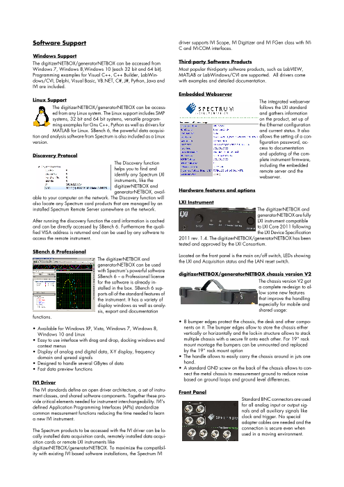
Embedded Webserver
Linux Support The integrated webserver
The digitizerNETBOX/generatorNETBOX can be access- follows the LXI standard
ed from any Linux system. The Linux support includes SMP and gathers information
systems, 32 bit and 64 bit systems, versatile program- on the product, set up of
ming examples for Gnu C++, Python as well as drivers for the Ethernet configuration
MATLAB for Linux. SBench 6, the powerful data acquisi- and current status. It also
tion and analysis software from Spectrum is also included as a Linux allows the setting of a con-
version. figuration password, ac-
cess to documentation
Discovery Protocol and updating of the com-
plete instrument firmware,
The Discovery function including the embedded
helps you to find and remote server and the
identify any Spectrum LXI webserver.
instruments, like the
digitizerNETBOX and
generatorNETBOX, avail- Hardware features and options
able to your computer on the network. The Discovery function will
also locate any Spectrum card products that are managed by an LXI Instrument
installed Spectrum Remote Server somewhere on the network. The digitizerNETBOX and
generatorNETBOX are fully
After running the discovery function the card information is cached LXI instrument compatible
and can be directly accessed by SBench 6. Furthermore the quali- to LXI Core 2011 following
fied VISA address is returned and can be used by any software to the LXI Device Specification
access the remote instrument. 2011 rev. 1.4. The digitizerNETBOX/generatorNETBOX has been
tested and approved by the LXI Consortium.
SBench 6 Professional
Located on the front panel is the main on/off switch, LEDs showing
The digitizerNETBOX and the LXI and Acquisition status and the LAN reset switch.
generatorNETBOX can be used
with Spectrum’s powerful software
SBench 6 – a Professional license digitizerNETBOX/generatorNETBOX chassis version V2
for the software is already in- The chassis version V2 got
stalled in the box. SBench 6 sup- a complete re-design to al-
ports all of the standard features of low some new features
the instrument. It has a variety of that improve the handling
display windows as well as analy- especially for mobile and
sis, export and documentation shared usage:
functions.
• 8 bumper edges protect the chassis, the desk and other compo-
• Available for Windows XP, Vista, Windows 7, Windows 8, nents on it. The bumper edges allow to store the chassis either
Windows 10 and Linux vertically or horizontally and the lock-in structure allows to stack
• Easy to use interface with drag and drop, docking windows and multiple chassis with a secure fit onto each other. For 19“ rack
context menus mount montage the bumpers can be unmounted and replaced
• Display of analog and digital data, X-Y display, frequency by the 19“ rack mount option
domain and spread signals • The handle allows to easily carry the chassis around in juts one
• Designed to handle several GBytes of data hand.
• Fast data preview functions • A standard GND screw on the back of the chassis allows to con-
nect the metal chassis to measurement ground to reduce noise
based on ground loops and ground level differences.
IVI Driver
The IVI standards define an open driver architecture, a set of instru- Front Panel
ment classes, and shared software components. Together these pro-
vide critical elements needed for instrument interchangeability. IVI's Standard BNC connectors are used
defined Application Programming Interfaces (APIs) standardize for all analog input or output sig-
common measurement functions reducing the time needed to learn nals and all auxiliary signals like
a new IVI instrument. clock and trigger. No special
adapter cables are needed and the
The Spectrum products to be accessed with the IVI driver can be lo- connection is secure even when
cally installed data acquisition cards, remotely installed data acqui- used in a moving environment.
sition cards or remote LXI instruments like
digitizerNETBOX/generatorNETBOX. To maximize the compatibil-
ity with existing IVI based software installations, the Spectrum IVI
Page4
Custom front panels are available on request even for small series, Automatic on-board calibration
be it SMA, LEMO connectors or custom specific connectors. All of the channels are calibrated in factory before the board is
shipped. To compensate for different variations like PC power sup-
Ethernet Connectivity ply, temperature and aging, the software driver provides routines
The GBit Ethernet connection can be for an automatic onboard offset and gain calibration of all input
used with standard COTS Ethernet ranges. All the cards contain a high precision on-board calibration
cabling. The integration into a stan- reference.
dard LAN allows to connect the
digitizerNETBOX/generatorNET- Ring buffer mode
BOX either directly to a desktop PC The ring buffer mode is the
or Laptop or it is possible to place standard mode of all oscillo-
the instrument somewhere in the scope instruments. Digitized
company LAN and access it from any desktop over the LAN. data is continuously written
into a ring memory until a
DC Power Supply Option trigger event is detected. After the trigger, post-trigger samples are
The digitizerNETBOX/generatorNET- recorded and pre-trigger samples can also be stored. The number
BOX can be equipped with an internal of pre-trigger samples available simply equals the total ring mem-
DC power supply which replaces the ory size minus the number of post trigger samples.
standard AC power supply. Two dif-
ferent power supply options are avail- FIFO mode
able that range from 9V to 36V. The FIFO mode is designed for continuous data transfer between re-
Contact the sales team if other DC lev- mote instrument and PC memory or hard disk. The control of the
els are required. data stream is done automatically by the driver on interrupt request.
The complete installed on-board memory is used for buffer data,
Using the DC power supply the digitiz- making the continuous streaming extremely reliable.
erNETBOX/generatorNETBOX can be used for mobile applications
together with a Laptop in automotive or airborne applications. Channel trigger
The data acquisition instruments offer a wide variety of trigger
Boot on Power on Option modes. Besides the standard signal checking for level and edge as
The digitizerNETBOX/generatorNETBOX can be factory config- known from oscilloscopes it’s also possible to define a window trig-
ured to automatically start and boot upon availability of the input ger. All trigger modes can be combined with the pulsewidth trigger.
power rail. That way the instrument will automatically become This makes it possible to trigger on signal errors like too long or too
available again upon loss of input power. short pulses. In addition to this a re-arming mode (for accurate trig-
ger recognition on noisy signals) the AND/OR conjunction of dif-
Input Amplifier ferent trigger events is possible. As a unique feature it is possible to
The analog inputs can be adapt- use deactivated channels as trigger sources.
ed to real world signals using a
wide variety of settings that are External trigger I/O
individual for each channel. By All instruments can be triggered using an external TTL signal. It’s
using software commands the in- possible to use positive or negative edge also in combination with
put termination can be changed a programmable pulse width. An internally recognised trigger
between 50 Ohm and 1 MOhm, one can select a matching input event can - when activated by software - be routed to the trigger
range and the signal offset can be compensated for. connector to start external instruments.
Differential inputs Pulse width
With a simple software command the inputs can individually be Defines the minimum or maximum width that a trigger pulse must
switched from single-ended (in relation to ground) to differential by have to generate a trigger event. Pulse width can be combined with
combining each two single-ended inputs to one differential input. channel trigger, pattern trigger and external trigger.
When the inputs are used in differential mode the A/D converter
measures the difference between two lines with relation to system Multiple Recording
ground.
The Multiple Recording
mode allows the recording of
Additional Digital Inputs several trigger events with an
The eight channel extremely short re-arming
version of the digitiz- time. The hardware doesn’t
erNETBOX can have need to be restarted in be-
an option with addi- tween. The on-board memory is divided in several segments of the
tional eight digital in- same size. Each of them is filled with data if a trigger event occurs.
put channels for Pre- and posttrigger of the segments can be programmed. The num-
mixed-mode opera- ber of acquired segments is only limited by the used memory and
tion. The eight addi- is unlimited when using FIFO mode.
tional digital
channels are accessi- Gated Sampling
ble through BNC connectors on the front panel. Together with the
standard three multi-purpose digital I/O lines the digitizerNETBOX The Gated Sampling mode
can have a total of 11 digital inputs channels together with eight allows data recording con-
analog input channels. When activated the digital data is stored in- trolled by an external gate
side the analog channel by reducing the analog resolution. signal. Data is only record-
ed if the gate signal has a
programmed level. In addi-
Page5
tion a pre-area before start of the gate signal as well as a post area
after end of the gate signal can be acquired. The number of gate
segments is only limited by the used memory and is unlimited when
using FIFO mode.
Timestamp
The timestamp function
writes the time positions of
the trigger events in an extra
memory. The timestamps are
relative to the start of record-
ing, a defined zero time, ex-
ternally synchronized to a radio clock, an IRIG-B a GPS receiver.
Using the external synchronization gives a precise time relation for
acquisitions of systems on different locations.
ABA mode
The ABA mode com-
bines slow continuous
data recording with fast
acquisition on trigger
events. The ABA mode
works like a slow data
logger combined with a
fast digitizer. The exact
position of the trigger events is stored as timestamps in an extra
memory.
Option Embedded Server
The option turns the digitizer-
NETBOX/generatorNETBOX
in a powerful PC that allows to
run own programs on a small
and remote data acquisition
system. The digitizerNET-
BOX/generatorNETBOX is en-
hanced by more memory, a powerful CPU, a freely accessable
internal SSD and a remote software development access method.
The digitizerNETBOX/generatorNETBOX can either run connected
to LAN or it can run totally independent, storing data to the internal
SSD. The original digitizerNETBOX/generatorNETBOX remote in-
strument functionality is still 100 % available. Running the embed-
ded server option it is possible to pre-calculate results based on the
acquired data, store acquisitions locally and to transfer just the re-
quired data or results parts in a client-server based software struc-
ture. A different example for the
digitizerNETBOX/generatorNETBOX embedded server is surveil-
lance/logger application which can run totally independent for
days and send notification emails only over LAN or offloads stored
data as soon as it’s connected again.
Access to the embedded server is done through a standard text
based Linux shell based on the ssh secure shell.
External clock I/O
Using a dedicated connector a sampling clock can be fed in from
an external system. It’s also possible to output the internally used
sampling clock to synchronise external equipment to this clock.
Reference clock
The option to use a precise
external reference clock
(normally 10 MHz) is nec-
essary to synchronize the
instrument for high-quality
measurements with external equipment (like a signal source). It’s
also possible to enhance the quality of the sampling clock in this
way. The driver automatically generates the requested sampling
clock from the fed in reference clock.
Page6
DN2 / DN6 Technical Data
Analog Inputs
Resolution 16 bit (can be reduced to acquire simultaneous digital inputs)
Input Range software programmable ±200 mV, ±500 mV, ±1 V, ±2 V, ±5 V, ±10 V
Input Type software programmable Single-ended or True Differential
Input Offset (single-ended) software programmable programmable to ±100% of input range in steps of 1%
ADC Differential non linearity (DNL) ADC only 591x: ±0.2/±0.8 LSB (typ./max.)
592x: ±0.2/±0.8 LSB (typ./max.)
593x: ±0.5/±0.9 LSB (typ./max.)
594x: ±0.5/±0.9 LSB (typ./max.)
596x: ±0.5/±0.9 LSB (typ./max.)
ADC Integral non linearity (INL) ADC only 591x: ±1.0/±2.3 LSB (typ./max.)
592x: ±1.0/±2.3 LSB (typ./max.)
593x: ±2.0/±7.5 LSB (typ./max.)
594x: ±2.0/±7.5 LSB (typ./max.)
596x: ±2.0/±7.5 LSB (typ./max.)
Offset error (full speed), DC signal after warm-up and calibration ≤ 0.1% of range
Gain error (full speed), DC signal after warm-up and calibration ≤ 0.1% of reading
AC accuracy 1 kHz signal ≤ 0.3% of reading
AC accuracy 50 kHz signal ≤ 0.5% of reading
Crosstalk: Signal 1 MHz, 50 Ω range ≤ ±1V ≤ 95 dB on adjacent channels
range ≥ ±2V ≤ 90 dB on adjacent channels
Crosstalk: Signal 10 MHz, 50 Ω range ≤ ±1V ≤ 87 dB on adjacent channels
range ≥ ±2V ≤ 85 dB on adjacent channels
Analog Input impedance software programmable 50 Ω /1 MΩ || 30 pF
Analog input coupling fixed DC
Over voltage protection range ≤ ±1V ±5 V (1 MΩ), 3.5 Vrms (50 Ω)
Over voltage protection range ≥ ±2V ±50 V (1 MΩ), 5 Vrms (50 Ω)
Anti-Aliasing Filter (digital filtering active) 591x (5 MS/s) Digital Anti-Aliasing filter at 40% of sampling rate. Examples:
5 MS/s sampling rate -> anit-aliasing filter at 2 MHz
1 MS/s sampling rate -> anti-aliasing filter at 400 kHz
Anti-Aliasing Filter (standard) 591x (5 MS/s) fixed 2.5 MHz 3rd order butterworth alike
592x (20 MS/s) fixed 10 MHz 3rd order butterworth alike
593x (40 MS/s) fixed 20 MHz 3rd order butterworth alike
594x (80 MS/s) fixed 40 MHz 3rd order butterworth alike
596x (125 MS/s) fixed 60 MHz 3rd order butterworth alike
CMRR (Common Mode Rejection Ratio) range ≤ ±1V 100 kHz: 75 dB, 1 MHz: 60 dB, 10 MHz: 40 dB
CMRR (Common Mode Rejection Ratio) range ≥ ±2V 100 kHz: 55 dB, 1 MHz: 52 dB, 10 MHz: 50 dB
Channel selection (single-ended inputs) software programmable 1, 2, 4 or 8 channels (maximum is model dependent)
Channel selection (true differential inputs) software programmable 1, 2 or 4 channels (maximum is model dependent)
Trigger
Available trigger modes software programmable Channel Trigger, External, Software, Window, Pulse, Re-Arm, Spike, Or/And, Delay
Trigger level resolution software programmable 14 bit
Trigger edge software programmable Rising edge, falling edge or both edges
Trigger pulse width software programmable 0 to [4G - 1] samples in steps of 1 sample
Trigger delay software programmable 0 to [4G - 1] samples in steps of 1 samples
Trigger holdoff (for Multi, ABA, Gate) software programmable 0 to [4G - 1] samples in steps of 1 samples
Multi, ABA, Gate: re-arming time < 40 samples (+ programmed pretrigger + programmed holdoff)
Pretrigger at Multi, ABA, Gate, FIFO software programmable 8 up to [32 kSamples / number of active channels] in steps of 8
Posttrigger software programmable 8 up to [8G - 4] samples in steps of 8 (defining pretrigger in standard scope mode)
Memory depth software programmable 16 up to [installed memory / number of active channels] samples in steps of 8
Multiple Recording/ABA segment size software programmable 8 up to [installed memory / number of active channels] samples in steps of 8
Internal/External trigger accuracy 1 sample
Timestamp modes software programmable Standard, Startreset, external reference clock on X1 (e.g. PPS from GPS, IRIG-B)
Data format Std., Startreset: 64 bit counter, increments with sample clock (reset manually or on start)
RefClock: 24 bit upper counter (increment with RefClock)
40 bit lower counter (increments with sample clock, reset with RefClock)
Extra data software programmable none, acquisition of X1/X2/X3 inputs at trigger time, trigger source (for OR trigger)
Size per stamp 128 bit = 16 bytes
External trigger Ext X1, X2, X3
External trigger type Single level comparator 3.3V LVTTL logic inputs
External trigger impedance software programmable 50 Ω / 5 kΩ For electrical specifications refer to
External trigger input level ±5 V (5 kΩ), ±2.5 V (50 Ω), „Multi Purpose I/O lines“ section.
External trigger over voltage protection ±20 V (5 kΩ), 5 Vrms (50 Ω)
External trigger sensitivity 200 mVpp
(minimum required signal swing)
External trigger level software programmable ±5 V in steps of 1 mV
External trigger bandwidth 50 Ω DC to 400 MHz n.a.
5 kΩ DC to 300 MHz DC to 125 MHz
Minimum external trigger pulse width ≥ 2 samples ≥ 2 samples
Page7
Multi Purpose I/O lines
Number of multi purpose output lines one, named X0
Number of multi purpose input/output lines three, named X1, X2, X3
Multi Purpose line X0 X1, X2, X3
Input: available signal types software programmable n.a. Synchronous Digital-In, Asynchronous Digital-In,
Timestamp Reference Clock, Logic trigger
Input: signal levels n.a. 3.3 V LVTTL
Input: impedance n.a. 10 kΩ to 3.3 V
Input: maximum voltage level n.a. -0.5 V to +4.0 V
Input: maximum bandwidth n.a. 125 MHz
Output: available signal types software programmable Run-, Arm-, Trigger-Output, Run-, Arm-, Trigger-Output,
Asynchronous Digital-Out, Asynchronous Digital-Out
ADC Clock Output
Output: impedance 50 Ω
Output: drive strength Capable of driving 50 Ω loads, maximum drive strength ±48 mA
Output: type / signal levels 3.3V LVTTL, TTL compatible for high impedance loads
Output: update rate (synchronous modes) sampling clock
Option DN2.59x-08-Dig
Number of additional multi-purpose I/O lines 8 (X4 to X11)
Input: signal levels 3.3 V LVTTL
Input: impedance 10 kΩ to 3.3 V
Input: maximum voltage level -0.5 V to +4.0 V
Input: maximum bandwidth 125 MHz
Input: available signal types software programmable Synchronous Digital-In, Asynchronous Digital-In
Output: available signal types software programmable Run-, Arm-, Trigger-Output, Asynchronous Digital-Out
Output: update rate (synchronous modes) sampling clock
Output: type / signal levels 3.3V LVTTL, TTL compatible for high impedance loads
Output: impedance 50 Ω
Output: drive strength Capable of driving 50 Ω loads, maximum drive strength ±48 mA
Clock
Clock Modes software programmable internal PLL, external clock, external reference clock, sync
Internal clock range (PLL mode) software programmable see „Clock Limitations and Bandwidth“ table below
Internal clock accuracy after warm-up ≤ ±1.0 ppm (at time of calibration in production)
Internal clock aging ≤ ±0.5 ppm / year
PLL clock setup granularity (int. or ext. reference) 1 Hz
External reference clock range software programmable 128 kHz up to 125 MHz
Direct external clock to internal clock delay 4.3 ns
Direct external clock range see „Clock Limitations and Bandwidth“ table below
Direct external clock minimum LOW/HIGH time see „Clock Limitations and Bandwidth“ table below
External clock type Single level comparator
External clock input level ±5 V (5 kΩ), ±2.5 V (50 Ω),
External clock input impedance software programmable 50 Ω / 5 kΩ
External clock over voltage protection ±20 V (5 kΩ), 5 Vrms (50 Ω)
External clock sensitivity 200 mVpp
(minimum required signal swing)
External clock level software programmable ±5 V in steps of 1mV
External clock edge rising edge used
External reference clock input duty cycle 45% - 55%
Clock output electrical specification Available via Multi Purpose output X0. Refer to „Multi Purpose I/O lines“ section.
Synchronization clock multiplier „N“ for software programmable N being a multiplier (1, 2, 3, 4, 5, ... Max) of the card with the currently slowest sampling clock.
different clocks on synchronized cards The card maximum (see „Clock Limitations and Bandwidth“ table below) must not be exceeded.
ABA mode clock divider for slow clock software programmable 8 up to (64k - 8) in steps of 8
Channel to channel skew on one card < 200 ps (typical)
Skew between star-hub synchronized cards < 100 ps (typical)
Connectors
Analog Inputs 9 mm BNC female (one for each single-ended input) Cable-Type: Cab-9m-xx-xx
Trigger Input 9 mm BNC female Cable-Type: Cab-9m-xx-xx
Clock/Reference Clock Input 9 mm BNC female Cable-Type: Cab-9m-xx-xx
Clock Output, Multi-Purpose X0 9 mm BNC female Cable-Type: Cab-9m-xx-xx
Multi-Purpose I/O X1, X2, X3 Programmable Direction 9 mm BNC female Cable-Type: Cab-9m-xx-xx
Page8
Option digitizerNETBOX/generatorNETBOX embedded server (DN2.xxx-Emb, DN6.xxx-Emb)
CPU Intel Quad Core 2 GHz
System memory 4 GByte RAM
System data storage Internal 128 GByte SSD
Development access Remote Linux command shell (ssh), no graphical interface (GUI) available
Accessible Hardware Full access to Spectrum instruments, LAN, front panel LEDs, RAM, SSD
Integrated operating system OpenSuse 12.2 with kernel 4.4.7.
Internal PCIe connection DN2.20, DN2.46, DN2.47, DN2.49, DN2.59, DN2.60 PCIe x1, Gen1
DN6.46, DN6.49, DN6.59
DN2.22, DN2.44, DN2.66 PCIe x1, Gen2
DN6.22, DN6.44, DN6.66
Ethernet specific details
LAN Connection Standard RJ45
LAN Speed Auto Sensing: GBit Ethernet, 100BASE-T, 10BASE-T
LAN IP address programmable DHCP (IPv4) with AutoIP fall-back (169.254.x.y), fixed IP (IPv4)
Sustained Streaming speed DN2.20, DN2.46, DN2.47, DN2.49, DN2.60 up to 70 MByte/s
DN6.46, DN6.49
DN2.59, DN2.22, DN2.44, DN2.66 up to 100 MByte/s
DN6.59, DN6.22, DN6.44, DN6.66
Used TCP/UDP Ports Webserver: 80 mDNS Daemon: 5353
VISA Discovery Protocol: 111, 9757 UPNP Daemon: 1900
Spectrum Remote Server: 1026, 5025
Power connection details
Mains AC power supply Input voltage: 100 to 240 VAC, 50 to 60 Hz
AC power supply connector IEC 60320-1-C14 (PC standard coupler)
Power supply cord power cord included for Schuko contact (CEE 7/7)
Serial connection details (DN2.xxx with hardware ≥ V11)
Serial connection (RS232) For diagnostic purposes only. Do not use, unless being instructed by a Spectrum support agent.
Certification, Compliance, Warranty
EMC Immunity Compliant with CE Mark
EMC Emission Compliant with CE Mark
Product warranty 5 years starting with the day of delivery
Software and firmware updates Life-time, free of charge
Clock Limitations and Bandwidth
M2p.591x, M2p.592x, M2p.593x M2p.594x M2p.596x
DN2.591-xx DN2.592-xx DN2.593-xx DN2.596-xx
DN6.591-xx DN6.592-xx DN6.593-xx DN6.596-xx
max internal clock (non-synchronized cards) 5 MS/s 20 MS/s 40 MS/s 80 MS/s 125 MS/s
min internal clock (non-synchronized cards) 1 kS/s 1 kS/s 1 kS/s 1 kS/s 1 kS/s
max internal clock (cards synchronized via star-hub) 5 MS/s 20 MS/s 40 MS/s 80 MS/s 125 MS/s
min internal clock (cards synchronized via star-hub) 128 kS/s 128 kS/s 128 kS/s 128 kS/s 128 kS/s
max direct external clock 5 MS/s 20 MS/s 40 MS/s 80 MS/s 125 MS/s
min direct external clock 1 MS/s 1 MS/s 1 MS/s 1 MS/s 1 MS/s
min direct external clock LOW time 25 ns 25 ns 4 ns 4 ns 4 ns
min direct external clock HIGH time 25 ns 25 ns 4 ns 4 ns 4 ns
-3 dB analog input bandwidth > 2.0 MHz > 10 MHz > 20 MHz > 40 MHz > 60 MHz
-3 dB analog input bandwidth, digital filter de-activated > 2.5 MHz n.a. n.a. n.a. n.a.
RMS Noise Level (Zero Noise), typical figures
M2p.591x, DN2.591-xx, DN6.591-xx
digital filtering active
Input Range ±200 mV ±500 mV ±1 ±2 V ±5 V ±10 V
Voltage resolution 6.1 µV 15.3 µV 30.5 µV 61.0 µV 152.6 µV 305.2 µV
50 Ω <1.5 LSB <10 µV <1.2 LSB <19 µV <1.0 LSB <31 µV <3.0 LSB <183 µV <1.6 LSB <245 µV <1.2 LSB <367 µV
1 MΩ <1.5 LSB <10 µV <1.2 LSB <19 µV <1.0 LSB <31 µV <3.0 LSB <183 µV <1.6 LSB <245 µV <1.2 LSB <367 µV
M2p.592x, DN2.592-xx, DN6.592-xx
Input Range ±200 mV ±500 mV ±1 ±2 V ±5 V ±10 V
Voltage resolution 6.1 µV 15.3 µV 30.5 µV 61.0 µV 152.6 µV 305.2 µV
50 Ω <4.0 LSB <25 µV <2.6 LSB <40 µV <2.1 LSB <65 µV <4.3 LSB <263 µV <2.6 LSB <397 µV <2.1 LSB <641 µV
1 MΩ <4.5 LSB <28 µV <3.0 LSB <46 µV <2.5 LSB <107 µV <4.5 LSB <275 µV <3.0 LSB <458 µV <2.5 LSB <763 µV
M2p.593x, DN2.593-xx, DN6.593-xx
Input Range ±200 mV ±500 mV ±1 ±2 V ±5 V ±10 V
Voltage resolution 6.1 µV 15.3 µV 30.5 µV 61.0 µV 152.6 µV 305.2 µV
50 Ω <6.0 LSB <37 µV <5.0 LSB <77 µV <4.5 LSB <138 µV <6.5 LSB <397 µV <5.0 LSB <763 µV <4.5 LSB <1.4 mV
1 MΩ <6.5 LSB <40 µV <5.0 LSB <77 µV <4.5 LSB <138 µV <6.5 LSB <397 µV <5.0 LSB <763 µV <4.5 LSB <1.4 mV
Page9
M2p.594x
Input Range ±200 mV ±500 mV ±1 ±2 V ±5 V ±10 V
Voltage resolution 6.1 µV 15.3 µV 30.5 µV 61.0 µV 152.6 µV 305.2 µV
50 Ω <7.0 LSB <43 µV <5.5 LSB <85 µV <4.5 LSB <138 µV <7.5 LSB <458 µV <5.5 LSB <840 µV <4.5 LSB <1.4 mV
1 MΩ <7.5 LSB <46 µV <5.8 LSB <89 µV <4.5 LSB <138 µV <7.7 LSB <470 µV <5.8 LSB <886 µV <4.5 LSB <1.4 mV
M2p.596x, DN2.596-xx, DN6.596-xx
Input Range ±200 mV ±500 mV ±1 ±2 V ±5 V ±10 V
Voltage resolution 6.1 µV 15.3 µV 30.5 µV 61.0 µV 152.6 µV 305.2 µV
50 Ω <9.0 LSB <55µV <6.8 LSB <104 µV <5.5 LSB <168 µV <9.0 LSB <550 µV <6.8 LSB <1.1 mV <5.5 LSB <1.7 mV
1 MΩ <9.5 LSB <58µV <7.1 LSB <109 µV <5.5 LSB <168 µV <9.5 LSB <580 µV <7.1 LSB <1.1 mV <5.5 LSB <1.7 mV
Dynamic Parameters, typical figures
M2p.591x, DN2.591-xx, DN6.591-xx
digital filtering active
Test - sampling rate 5 MS/s
Input Range ±200 mV ±500 mV ±1 V ±2 V
Test Signal Frequency 20 kHz 1 MHz 20 kHz 1 MHz 20 kHz 1 MHz 20 kHz 1 MHz
SNR (typ) ≥ 83.5 dB ≥ 82.8 dB ≥ 85.0 dB ≥ 84.9 dB ≥ 86.2 dB ≥ 85.7 dB n.a. n.a.
THD (typ) (≤ 84.4 dB) ≤ -93.5 dB (≤ 86.3 dB) ≤ -93.1 dB (≤ 86.9 dB) ≤ -91.8 dB n.a. n.a.
SFDR (typ), excl. harm. ≥ 103.0 dB ≥ 103.0 dB ≥ 104.0 dB ≥ 107.0 dB ≥ 103.0 dB ≥ 107.0 dB n.a. n.a.
ENOB (based on SNR) ≥ 13.6 LSB ≥ 13.4 LSB ≥ 13.8 LSB ≥ 13.8 LSB ≥ 14.0 LSB ≥ 13.9 LSB n.a. n.a.
ENOB (based on SINAD) ≥ 13.1 LSB ≥ 13.4 LSB ≥ 13.4 LSB ≥ 13.7 LSB ≥ 13.6 LSB ≥ 13.8 LSB n.a. n.a.
M2p.591x, DN2.591-xx, DN6.591-xx
digital filtering active
Test - sampling rate 3 MS/s 1 MS/s 500 kS/s 200 kS/s
Input Range ±200 mV ±1 V ±200 mV ±1 V ±200 mV ±1 V ±200 mV ±1 V
Test Signal Frequency 20 kHz 20 kHz 20 kHz 20 kHz
Input bandwidth due to digital filter 1.2 MHz 400 kHz 200 klHz 80 kHz
SNR (typ) ≥ 85.3 dB ≥ 86.6 dB ≥ 87.2 dB ≥ 89.1 dB ≥ 86.2 dB ≥ 89.7 dB ≥ 86.4 dB ≥ 89.4 dB
THD (typ) (≤ 88.9 dB) (≤ -88.5 dB) (≤ 86.4 dB) (≤ -88.6 dB) (≤ 86.9 dB) (≤ -90.8 dB) (≤ 89.7 dB) (≤ -93.8 dB)
SFDR (typ), excl. harm. ≥ 103.1 dB ≥ 103.6 dB ≥ 102.8 dB ≥ 105.6 dB ≥ 103.1 dB ≥ 103.1 dB ≥ 103.1 dB ≥ 103.5 dB
ENOB (based on SNR) ≥ 13.9 LSB ≥ 14.1 LSB ≥ 14.2 LSB ≥ 14.5 LSB ≥ 14.0 LSB ≥ 14.6 LSB ≥ 14.1 LSB ≥ 14.6 LSB
ENOB (based on SINAD) ≥ 13.5 LSB ≥ 13.7 LSB ≥ 13.6 LSB ≥ 14.0 LSB ≥ 13.6 LSB ≥ 14.2 LSB ≥ 13.8 LSB ≥ 14.3 LSB
(20 kHz measurements are missing the correct bandpass filter and therefore show a larger THD that is coming from the generator)
M2p.592x, DN2.592-xx, DN6.592-xx
Test - sampling rate 20 MS/s
Input Range ±200 mV ±500 mV ±1 V ±2 V
Test Signal Frequency 1 MHz n.a. 1 MHz n.a. 1 MHz n.a. 1 MHz n.a.
SNR (typ) ≥ 77.2 dB n.a. ≥ 79.8 dB n.a. ≥ 81.0 dB n.a. ≥ 75.0 dB n.a.
THD (typ) ≤ 92.5 dB n.a. ≤ -92.8 dB n.a. ≤ -89.5 dB n.a. ≤ -76.5 dB n.a.
SFDR (typ), excl. harm. ≥ 103.0 dB n.a. ≥ 103.0 dB n.a. ≥ 105.0 dB n.a. ≥ 93.0 dB n.a.
ENOB (based on SNR) ≥ 12.5 LSB n.a. ≥ 13.0 LSB n.a. ≥ 13.2 LSB n.a. ≥ 12.2 LSB n.a.
ENOB (based on SINAD) ≥ 12.5 LSB n.a. ≥ 13.0 LSB n.a. ≥ 13.1 LSB n.a. ≥ 11.8 LSB n.a.
M2p.593x, DN2.593-xx, DN6.593-xx
Test - sampling rate 40 MS/s
Input Range ±200 mV ±500 mV ±1 ±2 V
Test Signal Frequency 1 MHz 10 MHz 1 MHz 10 MHz 1 MHz 10 MHz 1 MHz 10 MHz
SNR (typ) ≥ 73.0 dB ≥ 72.6 dB ≥ 74.6 dB ≥ 74.4 dB ≥ 75.3 dB ≥ 75.3 dB ≥ 71.9 dB ≥ 71.8 dB
THD (typ) ≤ -87.8 dB ≤ -67.0 dB ≤ -89.0 dB ≤ -67.0 dB ≤ -86.1 dB ≤ -67.2 dB ≤ -79.0 dB ≤ -67.2 dB
SFDR (typ), excl. harm. ≥ 98.3 dB ≥ 96.5 dB ≥ 98.8 dB ≥ 99.5 dB ≥ 101.0 dB ≥ 100.0 dB ≥ 81.7 dB ≥ 91.3 dB
ENOB (based on SNR) ≥ 11.8 LSB ≥ 11.8 LSB ≥ 12.1 LSB ≥ 12.0 LSB ≥ 12.2 LSB ≥ 12.2 LSB ≥ 11.7 LSB ≥ 11.6 LSB
ENOB (based on SINAD) ≥ 11.8 LSB ≥ 10.7 LSB ≥ 12.1 LSB ≥ 10.7 LSB ≥ 12.2 LSB ≥ 10.8 LSB ≥ 11.6 LSB ≥ 10.7 LSB
M2p.594x
Test - sampling rate 80 MS/s
Input Range ±200 mV ±500 mV ±1 ±2 V
Test Signal Frequency 1 MHz 10 MHz 1 MHz 10 MHz 1 MHz 10 MHz 1 MHz 10 MHz
SNR (typ) ≥ 70.6 dB ≥ 70.5 dB ≥ 72.9 dB ≥ 72.8 dB ≥ 74.2 dB ≥ 74.2 dB ≥ 69.8 dB ≥ 69.8 dB
THD (typ) ≤ -87.3 dB ≤ -76.9 dB ≤ -86.6 dB ≤ -76.3 dB ≤ -84.8 dB ≤ -70.1 dB ≤ -79.0 dB ≤ -77.9 dB
SFDR (typ), excl. harm. ≥ 97.5 dB ≥ 105.0 dB ≥ 101.0 dB ≥ 104.0 dB ≥ 100.0 dB ≥ 100.0 dB ≥ 96.9 dB ≥ 96.6 dB
ENOB (based on SNR) ≥ 11.4 LSB ≥ 11.4 LSB ≥ 11.8 LSB ≥ 11.8 LSB ≥ 12.0 LSB ≥ 12.0 LSB ≥ 11.2 LSB ≥ 11.2 LSB
ENOB (based on SINAD) ≥ 11.4 LSB ≥ 11.3 LSB ≥ 11.8 LSB ≥ 11.5 LSB ≥ 12.0 LSB ≥ 11.1 LSB ≥ 11.2 LSB ≥ 11.2 LSB
M2p.596x, DN2.596-xx, DN6.596-xx
Test - sampling rate 125 MS/s
Input Range ±200 mV ±500 mV ±1 V ±2 V
Page10
M2p.596x, DN2.596-xx, DN6.596-xx
Test Signal Frequency 1 MHz 10 MHz 40 MHz 1 MHz 10 MHz 40 MHz 1 MHz 10 MHz 40 MHz 1 MHz 10 MHz 40 MHz
SNR (typ) ≥ 68.1 dB ≥ 66.2 dB ≥ 65.5 dB ≥ 70.5 dB ≥ 69.9 dB ≥ 68.7 dB ≥ 73.3 dB ≥ 72.7 dB ≥ 71.5 dB ≥ 67.8 dB ≥ 65.8 dB ≥ 65.1 dB
THD (typ) ≤ -81.5 dB ≤ -74.5 dB ≤ -53.7 dB ≤ -82.5 dB ≤ -77.6 dB ≤ -55.3 dB ≤ -83.3 dB ≤ -68.9 dB ≤ -57.3 dB ≤ -78.0 dB ≤ -75.6 dB ≤ -53.7 dB
SFDR (typ), excl. harm. ≥ 95.0 dB ≥ 93.4 dB ≥ 92.3 dB ≥ 97.5 dB ≥ 96.8 dB ≥ 94.0 dB ≥ 98.5 dB ≥ 98.1 dB ≥ 96.4 dB ≥ 91.5 dB ≥ 89.0 dB ≥ 89.0 dB
ENOB (based on SNR) ≥ 11.0 LSB ≥ 10.7 LSB ≥ 10.6 LSB ≥ 11.4 LSB ≥ 11.3 LSB ≥ 11.1 LSB ≥ 11.8 LSB ≥ 11.8 LSB ≥ 11.6 LSB ≥ 11.0 LSB ≥ 10.6 LSB ≥ 10.5 LSB
ENOB (based on SINAD) ≥ 11.0 LSB ≥ 10.6 LSB ≥ 8.6 LSB ≥ 11.4 LSB ≥ 11.1 LSB ≥ 8.9 LSB ≥ 11.7 LSB ≥ 11.0 LSB ≥ 9.2 LSB ≥ 10.9 LSB ≥ 10.6 LSB ≥ 8.6 LSB
Dynamic parameters are measured at ±1 V input range (if no other range is stated) and 50Ω termination with the samplerate specified in the table. Measured parameters are averaged
20 times to get typical values. Test signal is a pure sine wave generated by a signal generator and a matching bandpass filter. Amplitude is >99% of FSR. SNR and RMS noise parameters
may differ depending on the quality of the used PC. SNR = Signal to Noise Ratio, THD = Total Harmonic Distortion, SFDR = Spurious Free Dynamic Range, SINAD = Signal Noise and Dis-
tortion, ENOB = Effective Number of Bits.
DN2 specific Technical Data
Environmental and Physical Details DN2.xxx
Dimension of Chassis without connectors or bumpers L x W x H 366 mm x 267 mm x 87 mm
Dimension of Chassis with 19“ rack mount option L x W x H 366 mm x 482.6 mm x 87 mm (2U height)
Weight (1 internal acquisition/generation module) 6.3 kg, with rack mount kit: 6.8 kg
Weight (2 internal acquisition/generation modules) 6.7 kg, with rack mount kit 7.2 kg
Warm up time 20 minutes
Operating temperature 0°C to 40°C
Storage temperature -10°C to 70°C
Humidity 10% to 90%
Dimension of packing (single DN2) L x W x H 470 mm x 390 mm x 180 mm
Volume weight of Packing (single DN2) 7.0 kgs
Power Consumption
230 VAC 12 VDC 24 VDC
4 channel versions 0.12 A 28 W 2.7 A 32 W 1.3 A 32 W
8 channel versions 0.13 A 30 W 2.7 A 33 W 1.3 A 32 W
16 channel versions 0.21 A 48 W 4.2 A 51 W 2.1 A 50 W
MTBF
MTBF TBD
Page11
Block diagram of digitizerNETBOX DN2
• The number of maximum channels and internal digitizer modules and existance of a synchronization Star-Hub is model dependent.
Block diagram of digitzerNETBOX module DN2.59x
Page12
Order Information
The digitizerNETBOX is equipped with a large internal memory for data storage and supports standard acquisition (Scope), FIFO acquisition
(streaming), Multiple Recording, Gated Sampling, ABA mode and Timestamps. Operating system drivers for Windows/Linux 32 bit and
64 bit, drivers and examples for C/C++, IVI (Scope and Digitizer class), LabVIEW (Windows), MATLAB (Windows and Linux), .NET, Delphi,
Java, Python and a Professional license of the oscilloscope software SBench 6 are included.
The system is delivered with a connection cable meeting your countries power connection. Additional power connections with other standards
are available as option.
d igitizerNETBOX DN2 - Ethernet/LXI Interface
Order no. A/D Resolution Bandwidth Memory Single-Ended Inputs Differential Inputs
DN2.591-04 16 Bit 2.5 MHz 1 x 512 MSamples 4 channels 5 MS/s 4 channels 5 MS/s
DN2.591-08 16 Bit 2.5 MHz 1 x 512 MSamples 8 channels 5 MS/s 4 channels 5 MS/s
DN2.591-16 16 Bit 2.5 MHz 2 x 512 MSamples 16 channels 5 MS/s 8 channels 5 MS/s
DN2.592-04 16 Bit 10 MHz 1 x 512 MSamples 4 channels 20 MS/s 4 channels 20 MS/s
DN2.592-08 16 Bit 10 MHz 1 x 512 MSamples 8 channels 20 MS/s 4 channels 20 MS/s
DN2.592-16 16 Bit 10 MHz 2 x 512 MSamples 16 channels 20 MS/s 8 channels 20 MS/s
DN2.593-04 16 Bit 20 MHz 1 x 512 MSamples 4 channels 40 MS/s 4 channels 40 MS/s
DN2.593-08 16 Bit 20 MHz 1 x 512 MSamples 8 channels 40 MS/s 4 channels 40 MS/s
DN2.593-16 16 Bit 20 MHz 2 x 512 MSamples 16channels 40 MS/s 8 channels 40 MS/s
DN2.596-04 16 Bit 60 MHz 1 x 512 MSamples 4 channels 125 MS/s 4 channels 125 MS/s
DN2.596-08 16 Bit 60 MHz 1 x 512 MSamples 4 channels 125 MS/s 4 channels 125 MS/s
8 channels 80 MS/s
DN2.596-16 16 Bit 60 MHz 2 x 512 MSamples 8 channels 125 MS/s 8 channels 125 MS/s
16 channels 80 MS/s
Digital Options
Order no. Option
DN2.59x-08-Dig Only availabe for 8 channel models DN2.59x-08. The option gives 8 additional digital inputs with multiple data formats. All 8 digital inputs
are available on BNC conector on the front panel.
Options
Order no. Option
DN2.xxx-Rack 19“ rack mounting set for self mounting
DN2.xxx-Emb Extension to Embedded Server: CPU, more memory, SSD. Access via remote Linux secure shell (ssh)
DN2.xxx-DC12 12 VDC internal power supply. Replaces AC power supply. Accepts 9 V to 18 V DC input. Screw terminals.
DN2.xxx-DC24 24 VDC internal power supply. Replaces AC power supply. Accepts 18 V to 36 V DC input. Screw terminals
DN2.xxx-BTPWR Boot on Power On: the digitizerNETBOX/generatorNETBOX automatically boots if power is switched on.
Calibration
Order no. Option
DN2.xxx-Recal Recalibration of complete digitizerNETBOX/generatorNETBOX DN2 including calibration protocol
BNC Cables
The standard adapter cables are based on RG174 cables and have a nominal attenuation of 0.3 dB/m at 100 MHz.
for Connections Connection Length to SMA male to SMA female to BNC male to SMB female
All BNC male 80 cm Cab-9m-3mA-80 Cab-9m-3fA-80 Cab-9m-9m-80 Cab-9m-3f-80
All BNC male 200 cm Cab-9m-3mA-200 Cab-9m-3fA-200 Cab-9m-9m-200 Cab-9m-3f-200
Technical changes and printing errors possible
SBench, digitizerNETBOX and generatorNETBOX are registered trademarks of Spectrum Instrumentation GmbH. Microsoft, Visual C++, Windows, Windows 98, Windows NT, Window 2000, Windows XP, Windows Vista,
Windows 7, Windows 8 and Windows 10 are trademarks/registered trademarks of Microsoft Corporation. LabVIEW, DASYLab, Diadem and LabWindows/CVI are trademarks/registered trademarks of National Instruments
Corporation. MATLAB is a trademark/registered trademark of The Mathworks, Inc. Delphi and C++Builder are trademarks/registered trademarks of Embarcadero Technologies, Inc. Keysight VEE, VEE Pro and VEE OneLab
are trademarks/registered trademarks of Keysight Technologies, Inc. FlexPro is a registered trademark of Weisang GmbH & Co. KG. PCIe, PCI Express and PCI-X and PCI-SIG are trademarks of PCI-SIG. LXI is a registered
trademark of the LXI Consortium. PICMG and CompactPCI are trademarks of the PCI Industrial Computation Manufacturers Group. Oracle and Java are registered trademarks of Oracle and/or its affiliates. Intel and Intel Core
i3, Core i5, Core i7, Core i9 and Xeon are trademarks and/or registered trademarks of Intel Corporation. AMD, Opteron, Sempron, Phenom, FX, Ryzen and EPYC are trademarks and/or registered trademarks of Advanced
Micro Devices. NVIDIA, CUDA, GeForce, Quadro and Tesla are trademarks/registered trademarks of NVIDIA Corporation.