


AWG NETBOX DN6.66x 16ビット、 625MS/s, 1.25GS/s、6~24チャネル
AWG NETBOX DN6.66x 16ビット、 625MS/s, 1.25GS/s、6~24チャネル
このカタログについて
| ドキュメント名 | AWG NETBOX DN6.66x 16ビット、 625MS/s, 1.25GS/s、6~24チャネル |
|---|---|
| ドキュメント種別 | 製品カタログ |
| ファイルサイズ | 931.3Kb |
| 登録カテゴリ | |
| 取り扱い企業 | 株式会社エレクトロニカ IMT事業部 (この企業の取り扱いカタログ一覧) |
この企業の関連カタログ


このカタログの内容
Page1
generatorNETBOX
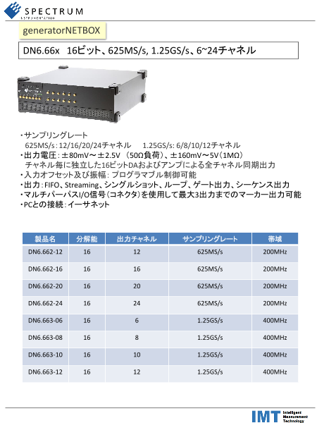
DN6.66x 16ビット、625MS/s, 1.25GS/s、6~24チャネル
・サンプリングレート
625MS/s:12/16/20/24チャネル 1.25GS/s: 6/8/10/12チャネル
・出力電圧:±80mV~±2.5V (50Ω負荷)、±160mV~5V(1MΩ)
チャネル毎に独立した16ビットDAおよびアンプによる全チャネル同期出力
・入力オフセット及び振幅:プログラマブル制御可能
・出力:FIFO、Streaming、シングルショット、ループ、ゲート出力、シーケンス出力
・マルチパーパスI/O信号(コネクタ)を使用して最大3出力までのマーカー出力可能
・PCとの接続:イーサネット
製品名 分解能 出力チャネル サンプリングレート 帯域
DN6.662-12 16 12 625MS/s 200MHz
DN6.662-16 16 16 625MS/s 200MHz
DN6.662-20 16 20 625MS/s 200MHz
DN6.662-24 16 24 625MS/s 200MHz
DN6.663-06 16 6 1.25GS/s 400MHz
DN6.663-08 16 8 1.25GS/s 400MHz
DN6.663-10 16 10 1.25GS/s 400MHz
DN6.663-12 16 12 1.25GS/s 400MHz
Page2
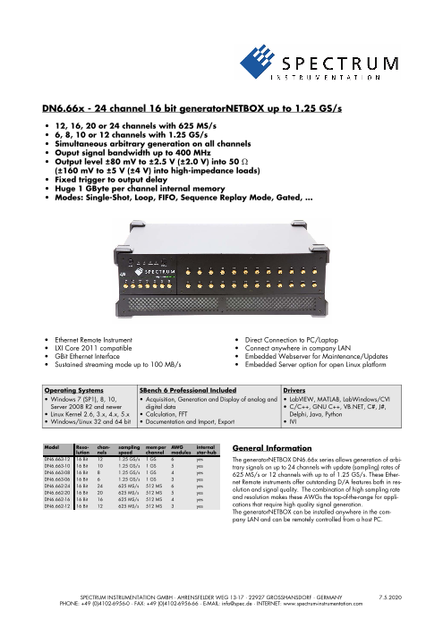
DN6.66x - 24 channel 16 bit generatorNETBOX up to 1.25 GS/s
• 12, 16, 20 or 24 channels with 625 MS/s
• 6, 8, 10 or 12 channels with 1.25 GS/s
• Simultaneous arbitrary generation on all channels
• Ouput signal bandwidth up to 400 MHz
• Output level ±80 mV to ±2.5 V (±2.0 V) into 50 Ω
(±160 mV to ±5 V (±4 V) into high-impedance loads)
• Fixed trigger to output delay
• Huge 1 GByte per channel internal memory
• Modes: Single-Shot, Loop, FIFO, Sequence Replay Mode, Gated, ...
• Ethernet Remote Instrument • Direct Connection to PC/Laptop
• LXI Core 2011 compatible • Connect anywhere in company LAN
• GBit Ethernet Interface • Embedded Webserver for Maintenance/Updates
• Sustained streaming mode up to 100 MB/s • Embedded Server option for open Linux platform
Operating Systems SBench 6 Professional Included Drivers
• Windows 7 (SP1), 8, 10, • Acquisition, Generation and Display of analog and • LabVIEW, MATLAB, LabWindows/CVI
Server 2008 R2 and newer digital data • C/C++, GNU C++, VB.NET, C#, J#,
• Linux Kernel 2.6, 3.x, 4.x, 5.x • Calculation, FFT Delphi, Java, Python
• Windows/Linux 32 and 64 bit • Documentation and Import, Export • IVI
Model Reso- chan- sampling mem per AWG internal General Information
lution nels speed channel modules star-hub
DN6.663-12 16 Bit 12 1.25 GS/s 1 GS 6 yes The generatorNETBOX DN6.66x series allows generation of arbi-
DN6.663-10 16 Bit 10 1.25 GS/s 1 GS 5 yes trary signals on up to 24 channels with update (sampling) rates of
DN6.663-08 16 Bit 8 1.25 GS/s 1 GS 4 yes 625 MS/s or 12 channels with up to of 1.25 GS/s. These Ether-
DN6.663-06 16 Bit 6 1.25 GS/s 1 GS 3 yes net Remote instruments offer outstanding D/A features both in res-
DN6.662-24 16 Bit 24 625 MS/s 512 MS 6 yes
DN6.662-20 16 Bit 20 625 MS/s 512 MS 5 yes olution and signal quality. The combination of high sampling rate
DN6.662-16 16 Bit 16 625 MS/s 512 MS 4 yes and resolution makes these AWGs the top-of-the-range for appli-
DN6.662-12 16 Bit 12 625 MS/s 512 MS 3 yes cations that require high quality signal generation.
The generatorNETBOX can be installed anywhere in the com-
pany LAN and can be remotely controlled from a host PC.SPECTRUM INSTRUMENTATION GMBH · AHRENSFELDER WEG 13-17 · 22927 GROSSHANSDORF · GERMANY 7.5.2020
PHONE: +49 (0)4102-6956-0 · FAX: +49 (0)4102-6956-66 · E-MAIL: info@spec.de · INTERNET: www.spectrum-instrumentation.com
Page3
digitizerNETBOX/generatorNETBOX. To maximize the compatibil-
ity with existing IVI based software installations, the Spectrum IVI
Software Support driver supports IVI Scope, IVI Digitizer and IVI FGen class with IVI-
C and IVI-COM interfaces.
Windows Support
The digitizerNETBOX/generatorNETBOX can be accessed from Third-party Software Products
Windows 7, Windows 8,Windows 10 (each 32 bit and 64 bit). Most popular third-party software products, such as LabVIEW,
Programming examples for Visual C++, C++ Builder, LabWin- MATLAB or LabWindows/CVI are supported. All drivers come
dows/CVI, Delphi, Visual Basic, VB.NET, C#, J#, Python, Java and with examples and detailed documentation.
IVI are included.
Embedded Webserver
Linux Support The integrated webserver
The digitizerNETBOX/generatorNETBOX can be access- follows the LXI standard
ed from any Linux system. The Linux support includes SMP and gathers information
systems, 32 bit and 64 bit systems, versatile program- on the product, set up of
ming examples for Gnu C++, Python as well as drivers for the Ethernet configuration
MATLAB for Linux. SBench 6, the powerful data acquisi- and current status. It also
tion and analysis software from Spectrum is also included as a Linux allows the setting of a con-
version. figuration password, ac-
cess to documentation
Discovery Protocol and updating of the com-
The Discovery function plete instrument firmware,
helps you to find and including the embedded
identify any Spectrum LXI remote server and the
instruments, like the webserver.
digitizerNETBOX and
generatorNETBOX, avail- Hardware features and options
able to your computer on the network. The Discovery function will
also locate any Spectrum card products that are managed by an LXI Instrument
installed Spectrum Remote Server somewhere on the network. The digitizerNETBOX and
After running the discovery function the card information is cached generatorNETBOX are fully
and can be directly accessed by SBench 6. Furthermore the quali- LXI instrument compatible
fied VISA address is returned and can be used by any software to to LXI Core 2011 following
access the remote instrument. the LXI Device Specification 2011 rev. 1.4. The digitizerNETBOX/generatorNETBOX has been
tested and approved by the LXI Consortium.
SBench 6 Professional
The digitizerNETBOX and Located on the front panel is the main on/off switch, LEDs showing
generatorNETBOX can be used the LXI and Acquisition status and the LAN reset switch.
with Spectrum’s powerful software
SBench 6 – a Professional license Front Panel
for the software is already in- Standard SMA connectors are used for
stalled in the box. SBench 6 sup- all analog input signals and all trigger
ports all of the standard features of and clock signals. No special adapter
the instrument. It has a variety of cables are needed and the connection is
display windows as well as analy- secure even when used in a moving envi-
sis, export and documentation ronment.
functions.
Custom front panels are available on re-
• Available for Windows XP, Vista, Windows 7, Windows 8, quest even for small series, be it BNC, LEMO connectors or custom
Windows 10 and Linux specific connectors.
• Easy to use interface with drag and drop, docking windows and
context menus
• Display of analog and digital data, X-Y display, frequency Ethernet Connectivity
domain and spread signals The GBit Ethernet connection can be
• Designed to handle several GBytes of data used with standard COTS Ethernet
• Fast data preview functions cabling. The integration into a stan-
dard LAN allows to connect the
digitizerNETBOX/generatorNET-
IVI Driver BOX either directly to a desktop PC
The IVI standards define an open driver architecture, a set of instru- or Laptop or it is possible to place
ment classes, and shared software components. Together these pro- the instrument somewhere in the
vide critical elements needed for instrument interchangeability. IVI's company LAN and access it from any desktop over the LAN.
defined Application Programming Interfaces (APIs) standardize
common measurement functions reducing the time needed to learn Boot on Power on Option
a new IVI instrument. The digitizerNETBOX/generatorNETBOX can be factory config-
The Spectrum products to be accessed with the IVI driver can be lo- ured to automatically start and boot upon availability of the input
cally installed data acquisition cards, remotely installed data acqui- power rail. That way the instrument will automatically become
sition cards or remote LXI instruments like available again upon loss of input power.
Page4
Option Embedded Server gate signal has attained a programmed level.
The option turns the digitizer-
NETBOX/generatorNETBOX Sequence Mode
in a powerful PC that allows to The sequence
run own programs on a small mode allows to
and remote data acquisition split the card
system. The digitizerNET- memory into sev-
BOX/generatorNETBOX is en- eral data segments of different length. These data segments are
hanced by more memory, a powerful CPU, a freely accessable chained up in a user chosen order using an additional sequence
internal SSD and a remote software development access method. memory. In this sequence memory the number of loops for each seg-
ment can be programmed and trigger conditions can be defined to
The digitizerNETBOX/generatorNETBOX can either run connected proceed from segment to segment. Using the sequence mode it is
to LAN or it can run totally independent, storing data to the internal also possible to switch between replay waveforms by a simple soft-
SSD. The original digitizerNETBOX/generatorNETBOX remote in- ware command or to redefine waveform data for segments simulta-
strument functionality is still 100 % available. Running the embed- neously while other segments are being replayed. All trigger-
ded server option it is possible to pre-calculate results based on the related and software-command-related functions are only working
acquired data, store acquisitions locally and to transfer just the re- on single cards, not on star-hub-synchrnonized cards.
quired data or results parts in a client-server based software struc-
ture. A different example for the External trigger input
digitizerNETBOX/generatorNETBOX embedded server is surveil-
lance/logger application which can run totally independent for All boards can be triggered using up to two external analog or dig-
days and send notification emails only over LAN or offloads stored ital signals. One external trigger input has two analog comparators
data as soon as it’s connected again. that can define an edge or window trigger, a hysteresis trigger or
a rearm trigger. The other input has one comparator that can be
Access to the embedded server is done through a standard text used for standard edge and level triggers.
based Linux shell based on the ssh secure shell.
External clock input and output
Singleshot output Using a dedicated connector a sampling clock can be fed in from
When singleshot output is activated the data of the on-board mem- an external system. Additionally it’s also possible to output the in-
ory is played exactly one time. The trigger source can be either one ternally used sampling clock on a separate connector to synchro-
of the external trigger inputs or the software trigger. After the first nize external equipment to this clock.
trigger additional trigger events will be ignored.
Reference clock
Repeated output The option to use a precise
When the repeated output mode is used the data of the on-board external reference clock
memory is played continuously for a programmed number of times (normally 10 MHz) is nec-
or until a stop command is executed. The trigger source can be ei- essary to synchronize the
ther one of the external trigger inputs or the software trigger. After instrument for high-quality
the first trigger additional trigger events will be ignored. measurements with external equipment (like a signal source). It’s
also possible to enhance the quality of the sampling clock in this
way. The driver automatically generates the requested sampling
Single Restart replay clock from the fed in reference clock.
When this mode is activated the data of the on-board memory will
be replayed once after each trigger event. The trigger source can External clock input and output
be either the external TTL trigger or software trigger.
Using a dedicated connector a sampling clock can be fed in from
an external system. Additionally it’s also possible to output the in-
FIFO mode ternally used sampling clock on a separate connector to synchro-
The FIFO mode is designed for continuous data transfer between nize external equipment to this clock.
PC memory or hard disk and the generation board. The control of
the data stream is done automatically by the driver on an interrupt
request basis. The complete installed on-board memory is used for
buffering data, making the continuous streaming extremely reliable.
Multiple Replay
The Multiple Replay mode al-
lows the fast output genera-
tion on several trigger events
without restarting the hard-
ware. With this option very
fast repetition rates can be
achieved. The on-board memory is divided into several segments of
the same size. Each segment can contain different data which will
then be played with the occurrence of each trigger event.
Gated Replay
The Gated Sampling mode al-
lows data replay controlled
by an external gate signal.
Data is only replayed if the
Page5
Technical Data
Analog Outputs
Resolution 16 bit
D/A Interpolation no interpolation
M4i.662x/M4x.662x M4i.663x/M4x.663x high bandwidth version
DN2.662/DN6.662x DN2.663/DN6.663 (1.25 GS/s + option -hbw)
Output amplitude into 50 Ω termination software programmable ±80 mV up to ±2.5 V ±80 mV up to ±2 V ±80 mV up to ±480 mV
Output amplitude into high impedance loads software programmable ±160 mV up to ±5 V ±160 mV up to ±4 V ±160 mV up to ±960 mV
Stepsize of output amplitude (50 Ω termination) 1 mV 1 mV 1 mV
Stepsize of output amplitude (high impedance) 2 mV 2 mV 2 mV
10% to 90% rise/fall time of 480 mV pulse 1.06 ns 440 ps
10% to 90% rise/fall time of 2000 mV pulse 1.08 ns n.a.
Output offset fixed 0 V
Output Amplifier Path Selection automatically by driver Low Power path: ±80 mV to ±480 mV (into 50 Ω)
High Power path: ±420 mV to ±2.5 V/±2 V (into 50 Ω)
Output Amplifier Setting Hysteresis automatically by driver 420 mV to 480 mV (if output is using low power path it will switch to high power path at
480 mV. If output is using high power path it will switch to low power path at 420 mV)
Output amplifier path switching time 10 ms (output disabled while switching)
Filters software programmable bypass with no filter or one fixed filter
DAC Differential non linearity (DNL) DAC only ±0.5 LSB typical
DAC Integral non linearity (INL) DAC only ±1.0 LSB typical
Output resistance 50 Ω
Minimum output load 0 Ω (short circuit safe)
Output accuracy Low power path ±0.5 mV ±0.1% of programmed output amplitude
High power path ±1.0 mV ±0.2% of programmed output amplitude
Trigger
Available trigger modes software programmable External, Software, Window, Re-Arm, Or/And, Delay, PXI (M4x only)
Trigger edge software programmable Rising edge, falling edge or both edges
Trigger delay software programmable 0 to (8GSamples - 32) = 8589934560 Samples in steps of 32 samples
Multi, Gate: re-arming time 40 samples
Trigger to Output Delay sample rate ≤ 625 MS/s 238.5 sample clocks + 16 ns
sample rate > 625 MS/s 476.5 sample clocks + 16 ns
Memory depth software programmable 32 up to [installed memory / number of active channels] samples in steps of 32
Multiple Replay segment size software programmable 16 up to [installed memory / 2 / active channels] samples in steps of 16
Trigger accuracy (all sources) 1 sample
Minimum external trigger pulse width ≥ 2 samples
External trigger Ext0 Ext1
External trigger impedance software programmable 50 Ω /1 kΩ 1 kΩ
External trigger coupling software programmable AC or DC fixed DC
External trigger type Window comparator Single level comparator
External input level ±10 V (1 kΩ), ±2.5 V (50 Ω), ±10 V
External trigger sensitivity 2.5% of full scale range 2.5% of full scale range = 0.5 V
(minimum required signal swing)
External trigger level software programmable ±10 V in steps of 10 mV ±10 V in steps of 10 mV
External trigger maximum voltage ±30V ±30 V
External trigger bandwidth DC 50 Ω DC to 200 MHz n.a.
1 kΩ DC to 150 MHz DC to 200 MHz
External trigger bandwidth AC 50 Ω 20 kHz to 200 MHz n.a.
Minimum external trigger pulse width ≥ 2 samples ≥ 2 samples
Clock
Clock Modes software programmable internal PLL, external reference clock, Star-Hub sync (M4i only), PXI Reference Clock (M4x only)
Internal clock accuracy ≤ ±20 ppm
Internal clock setup granularity 8 Hz (internal reference clock only, restrictions apply to external reference clock)
Setable Clock speeds 50 MHz to max sampling clock
Clock Setting Gaps 750 to 757 MHz, 1125 to 1145 MHz (no sampling clock possible in these gaps)
External reference clock range software programmable ≥ 10 MHz and ≤ 1.25 GHz
External reference clock input impedance 50 Ω fixed
External reference clock input coupling AC coupling
External reference clock input edge Rising edge
External reference clock input type Single-ended, sine wave or square wave
External reference clock input swing 0.3 V peak-peak up to 3.0 V peak-peak
External reference clock input max DC voltage ±30 V (with max 3.0 V difference between low and high level)
External reference clock input duty cycle requirement 45% to 55%
External reference clock output type Single-ended, 3.3V LVPECL
Clock output sampling clock ≤71.68 MHz Clock output = sampling clock/4
Clock output sampling clock >71.68 MHz Clock output = sampling clock/8
Star-Hub synchronization clock modes software selectable Internal clock, external reference clock
Page6
Sequence Replay Mode (Mode available starting with firmware V1.14)
Number of sequence steps software programmable 1 up to 4096 (sequence steps can be overloaded at runtime)
Number of memory segments software programmable 2 up to 64k (segment data can be overloaded at runtime)
Minimum segment size software programmable 384 samples (1 active channel), 192 samples (2 active channels),
96 samples (4 active channels), in steps of 32 samples.
Maximum segment size software programmable 2 GS / active channels / number of sequence segments (round up to the next power of two)
Loop Count software programmable 1 to (1M - 1) loops
Sequence Step Commands software programmable Loop for #Loops, Next, Loop until Trigger, End Sequence
Special Commands software programmable Data Overload at runtime, sequence steps overload at runtime,
readout current replayed sequence step
Limitations for synchronized products Software commands changing the sequence as well as „Loop until trigger“ are not synchronized
between cards. This also applies to multiple AWG modules in a generatorNETBOX.
Multi Purpose I/O lines (front-plate)
Number of multi purpose lines three, named X0, X1, X2
Input: available signal types software programmable Asynchronous Digital-In
Input: impedance 10 kΩ to 3.3 V
Input: maximum voltage level -0.5 V to +4.0 V
Input: signal levels 3.3 V LVTTL
Output: available signal types software programmable Asynchronous Digital-Out, Synchronous Digital-Out, Trigger Output,
Run, Arm, Marker Output, System Clock
Output: impedance 50 Ω
Output: signal levels 3.3 V LVTTL
Output: type 3.3V LVTTL, TTL compatible for high impedance loads
Output: drive strength Capable of driving 50 Ω loads, maximum drive strength ±48 mA
Output: update rate sampling clock
Connectors
Analog Channels SMA female (one for each single-ended input) Cable-Type: Cab-3mA-xx-xx
Clock Input SMA female Cable-Type: Cab-3mA-xx-xx
Clock Output SMA female Cable-Type: Cab-3mA-xx-xx
Trg0 Input SMA female Cable-Type: Cab-3mA-xx-xx
Trg1 Input SMA female Cable-Type: Cab-3mAxx-xx
X0/Trigger Output/Timestamp Reference Clock programmable direction SMA female Cable-Type: Cab-3mA-xx-xx
X1 programmable direction SMA female Cable-Type: Cab-3mA-xx-xx
X2 programmable direction SMA female Cable-Type: Cab-3mA-xx-xx
Option digitizerNETBOX/generatorNETBOX embedded server (DN2.xxx-Emb, DN6.xxx-Emb)
CPU Intel Quad Core 2 GHz
System memory 4 GByte RAM
System data storage Internal 128 GByte SSD
Development access Remote Linux command shell (ssh), no graphical interface (GUI) available
Accessible Hardware Full access to Spectrum instruments, LAN, front panel LEDs, RAM, SSD
Integrated operating system OpenSuse 12.2 with kernel 4.4.7.
Internal PCIe connection DN2.20, DN2.46, DN2.47, DN2.49, DN2.59, DN2.60 PCIe x1, Gen1
DN6.46, DN6.49, DN6.59
DN2.22, DN2.44, DN2.66 PCIe x1, Gen2
DN6.22, DN6.44, DN6.66
Ethernet specific details
LAN Connection Standard RJ45
LAN Speed Auto Sensing: GBit Ethernet, 100BASE-T, 10BASE-T
LAN IP address programmable DHCP (IPv4) with AutoIP fall-back (169.254.x.y), fixed IP (IPv4)
Sustained Streaming speed DN2.20, DN2.46, DN2.47, DN2.49, DN2.60 up to 70 MByte/s
DN6.46, DN6.49
DN2.59, DN2.22, DN2.44, DN2.66 up to 100 MByte/s
DN6.59, DN6.22, DN6.44, DN6.66
Used TCP/UDP Ports Webserver: 80 mDNS Daemon: 5353
VISA Discovery Protocol: 111, 9757 UPNP Daemon: 1900
Spectrum Remote Server: 1026, 5025
Power connection details
Mains AC power supply Input voltage: 100 to 240 VAC, 50 to 60 Hz
AC power supply connector IEC 60320-1-C14 (PC standard coupler)
Power supply cord power cord included for Schuko contact (CEE 7/7)
Serial connection details (DN2.xxx with hardware ≥ V11)
Serial connection (RS232) For diagnostic purposes only. Do not use, unless being instructed by a Spectrum support agent.
Page7
Certification, Compliance, Warranty
EMC Immunity Compliant with CE Mark
EMC Emission Compliant with CE Mark
Product warranty 5 years starting with the day of delivery
Software and firmware updates Life-time, free of charge
Bandwidth and Slewrate
Filter Output Amplitude M4i.663x-x8 M4i.662x-x8
M4x.663x-x8 M4x.662x-x8
DN2.663-xx DN2.662-xx
DN6.663-xx DN6.662-xx
Maximum Output Rate 1.25 GS/s 625 MS/s
-3dB Bandwidth no Filter ±480 mV 400 MHz 200 MHz
-3dB Bandwidth no Filter ±1000 mV 320 MHz 200 MHz
-3dB Bandwidth no Filter ±2000 mV 320 MHz 200 MHz
-3dB Bandwidth Filter all 65 MHz 65 MHz
Slewrate no Filter ±480 mV 4.5 V/ns 2.25 V/ns
Dynamic Parameters
M4i.662x-x8
M4x.662x-x8
DN2.662-xx
DN6.662-xx
Test - Samplerate 625 MS/s 625 MS/s 625 MS/s
Output Frequency 10 MHz 50 MHz 50 MHz
Output Level in 50 Ω ±480 mV ±1000mV ±2500mV ±480 mV ±2500mV ±480 mV ±2500mV
Used Filter none none Filter enabled
NSD (typ) -150 dBm/Hz -149 dBm/Hz -149 dBm/Hz -150 dBm/Hz -149 dBm/Hz -150 dBm/Hz -149 dBm/Hz
SNR (typ) 70.7 dB 72.4 dB 63.1 dB 65.3 dB 64.4 dB 67.5 dB 69.4 dB
THD (typ) -73.3 dB -70.5 dB -49.7 dB -64.1 dB -39.1 dB -68.4 dB -50.4 dB
SINAD (typ) 69.0 dB 67.7 dB 49.5 dB 61.6 dB 39.1 dB 64.9 dB 50.3 dB
SFDR (typ), excl harm. 98 dB 98 dB 99 dB 86 dB 76 dB 88 dB 89 dB
ENOB (SINAD) 11.2 11.0 8.0 10.0 6.2 10.5 8.1
ENOB (SNR) 11.5 11.7 10.2 10.5 10.4 10.9 11.2
M4i.663x-x8
M4x.663x-x8
DN2.663-xx
DN6.663-xx
Test - Samplerate 1.25 GS/s 1.25 GS/s 1.25 GS/s
Output Frequency 10 MHz 50 MHz 50 MHz
Output Level in 50 Ω ±480 mV ±1000mV ±2000mV ±480 mV ±2000mV ±480 mV ±2000mV
Used Filter none none Filter enabled
NSD (typ) -150 dBm/Hz -149 dBm/Hz -149 dBm/Hz -150 dBm/Hz -149 dBm/Hz -150 dBm/Hz -149 dBm/Hz
SNR (typ) 70.5 dB 72.1 dB 71.4 dB 65.2 dB 65.0 dB 67.2 dB 68.2 dB
THD (typ) -74.5 dB -73.5 dB -59.1 dB -60.9 dB -43.9 dB -67.9 dB -63.1 dB
SINAD (typ) 69.3 dB 69.7 dB 59 dB 59.5 dB 43.9 dB 64.5 dB 61.9 dB
SFDR (typ), excl harm. 96 dB 97 dB 98 dB 85 dB 84 dB 87 dB 87 dB
ENOB (SINAD) 11.2 11.2 9.5 9.6 6.9 10.4 10.0
ENOB (SNR) 11.5 11.5 11.5 10.5 10.5 10.9 11.0
THD and SFDR are measured at the given output level and 50 Ohm termination with a high resolution M3i.4860/M4i.4450-x8 data acquisition card and are calculated from the spec-
trum. Noise Spectral Density is measured with built-in calculation from an HP E4401B Spectrum Analyzer. All available D/A channels are activated for the tests. SNR and SFDR figures
may differ depending on the quality of the used PC. NSD = Noise Spectral Density, THD = Total Harmonic Distortion, SFDR = Spurious Free Dynamic Range.
Page8
DN6 specific Technical Data
Environmental and Physical Details DN6.xxx
Dimension of Chassis without connectors or bumpers L x W x H 464 mm x 431 mm x 131 mm
Dimension of Chassis with 19“ rack mount option L x W x H 464 mm x TBD mm x 131 mm (3U height)
Weight (3 internal acquisition/generation modules) 12.1 kg, with rack mount kit: TBD kg
Weight (4 internal acquisition/generation modules) 12.5 kg, with rack mount kit: TBD kg
Weight (5 internal acquisition/generation modules) 12.9 kg, with rack mount kit: TBD kg
Weight (6 internal acquisition/generation modules) 13.4 kg, with rack mount kit: TBD kg
Warm up time 10 minutes
Operating temperature 0°C to 40°C
Storage temperature -10°C to 70°C
Humidity 10% to 90%
Dimension of packing (single DN6) L x W x H 580 mm x 580 mm x 280 mm
Volume weight of Packing (single DN6) 19.0 kgs
Power Consumption
230 VAC
DN6.662-12, DN6.663-06 0.55 A 127 W
DN6.662-16, DN6.663-08 0.77 A 179 W
DN6.662-20, DN6.663-10 TBD TBD
DN6.662-24, DN6.663-12 TBD TBD
MTBF
MTBF 100000 hours
Page9
Block diagram of generatorNETBOX DN6
Block diagram of generatorNETBOX AWG module DN6.66x
Page10
Order Information
The generatorNETBOX is equipped with a large internal memory and supports standard replay, FIFO replay (streaming), Multiple Replay,
Gated Replay, Continuous Replay (Loop), Single-Restart as well as Sequence. Operating system drivers for Windows/Linux 32 bit and 64
bit, drivers and examples for C/C++, IVI (Function Generator class), LabVIEW (Windows), MATLAB (Windows and Linux), .NET, Delphi,
Java, Python and a Professional license of the oscilloscope software SBench 6 are included.
The system is delivered with a connection cable meeting your countries power connection. Additional power connections with other standards
are available as option.
generatorNETBOX DN6 - Ethernet/LXI Interface
Order no. D/A Bandwidth Single-Ended Update Rate Installed
Resolution Channels Memory
DN6.662-12 16 Bit 200 MHz 12 channels 625 MS/s 3 x 2 GS
DN6.662-16 16 Bit 200 MHz 16 channels 625 MS/s 4 x 2 GS
DN6.662-20 16 Bit 200 MHz 20 channels 625 MS/s 5 x 2 GS
DN6.662-24 16 Bit 200 MHz 24 channels 625 MS/s 6 x 2 GS
DN6.663-06 16 Bit 400 MHz 6 channels 1.25 GS/s 3 x 2 GS
DN6.663-08 16 Bit 400 MHz 8 channels 1.25 GS/s 4 x 2 GS
DN6.663-10 16 Bit 400 MHz 10 channels 1.25 GS/s 5 x 2 GS
DN6.663-12 16 Bit 400 MHz 12 channels 1.25 GS/s 6 x 2 GS
Options
Order no. Option
DN6.xxx-Rack 19“ rack mounting set for self mounting
DN6.xxx-Emb Extension to Embedded Server: CPU, more memory, SSD. Access via remote Linuxs secure shell (ssh)
DN6.xxx-BTPWR Boot on Power On: the generatorNETBOX automatically boots if power is switched on.
M4i.663x-hbw High bandwidth option 600 MHz. Output level limited to ±480 mV into 50 Ω. Needs external reconstruction filter. One option needed per
internal AWG card.
Calibration
Order no. Option
DN6.xxx-Recal Recalibration of complete digitizerNETBOX/generatorNETBOX DN6 including calibration protocol
Standard SMA Cables
The standard adapter cables are based on RG174 cables and have a nominal attenuation of 0.3 dB/m at 100 MHz and 0.5 dB/m at
250 MHz. For high speed signals we recommend the low loss cables series CHF.
for Connections Connection Length to BNC male to BNC female to SMB female to MMCX male to SMA male
All SMA male 80 cm Cab-3mA-9m-80 Cab-3mA-9f-80 Cab-3f-3mA-80 Cab-1m-3mA-80 Cab-3mA-3mA-80
All SMA male 200 cm Cab-3mA-9m-200 Cab-3mA-9f-200 Cab-3f-3mA-200 Cab-1m-3mA-200 Cab-3mA-3mA-200
Probes (short) SMA male 5 cm Cab-3mA-9f-5
Low Loss SMA Cables
The low loss adapter cables are based on MF141 cables and have an attenuation of 0.3 dB/m at 500 MHz and 0.5 dB/m at 1.5 GHz.
They are recommended for signal frequencies of 200 MHz and above.
Order no. Option
CHF-3mA-3mA-200 Low loss cables SMA male to SMA male 200 cm
CHF-3mA-9m-200 Low loss cables SMA male to BNC male 200 cm
Technical changes and printing errors possible
SBench, digitizerNETBOX and generatorNETBOX are registered trademarks of Spectrum Instrumentation GmbH. Microsoft, Visual C++, Windows, Windows 98, Windows NT, Window 2000, Windows XP, Windows Vista,
Windows 7, Windows 8 and Windows 10 are trademarks/registered trademarks of Microsoft Corporation. LabVIEW, DASYLab, Diadem and LabWindows/CVI are trademarks/registered trademarks of National Instruments
Corporation. MATLAB is a trademark/registered trademark of The Mathworks, Inc. Delphi and C++Builder are trademarks/registered trademarks of Embarcadero Technologies, Inc. Keysight VEE, VEE Pro and VEE OneLab
are trademarks/registered trademarks of Keysight Technologies, Inc. FlexPro is a registered trademark of Weisang GmbH & Co. KG. PCIe, PCI Express and PCI-X and PCI-SIG are trademarks of PCI-SIG. LXI is a registered
trademark of the LXI Consortium. PICMG and CompactPCI are trademarks of the PCI Industrial Computation Manufacturers Group. Oracle and Java are registered trademarks of Oracle and/or its affiliates. Intel and Intel Core
i3, Core i5, Core i7, Core i9 and Xeon are trademarks and/or registered trademarks of Intel Corporation. AMD, Opteron, Sempron, Phenom, FX, Ryzen and EPYC are trademarks and/or registered trademarks of Advanced
Micro Devices. NVIDIA, CUDA, GeForce, Quadro and Tesla are trademarks/registered trademarks of NVIDIA Corporation.