


AWG M2p.65xx 16ビット、 40MS/s, 125MS/s、1,2,4,8チャネル
AWG M2p.65xx 16ビット、 40MS/s, 125MS/s、1,2,4,8チャネル
このカタログについて
| ドキュメント名 | AWG M2p.65xx 16ビット、 40MS/s, 125MS/s、1,2,4,8チャネル |
|---|---|
| ドキュメント種別 | 製品カタログ |
| ファイルサイズ | 994.9Kb |
| 登録カテゴリ | |
| 取り扱い企業 | 株式会社エレクトロニカ IMT事業部 (この企業の取り扱いカタログ一覧) |
この企業の関連カタログ


このカタログの内容
Page1
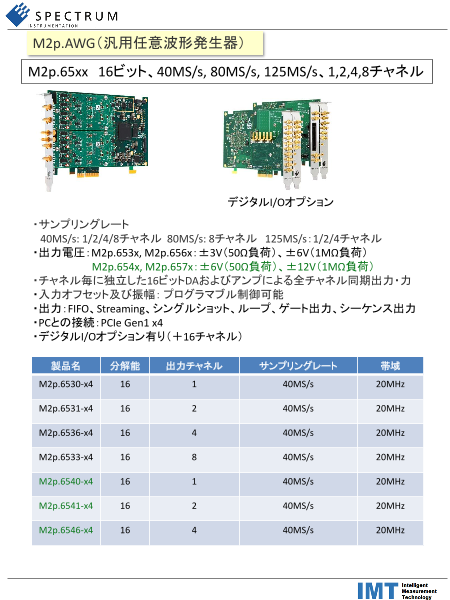
M2p.AWG(汎用任意波形発生器)
M2p.65xx 16ビット、40MS/s, 80MS/s, 125MS/s、1,2,4,8チャネル
デジタルI/Oオプション
・サンプリングレート
40MS/s: 1/2/4/8チャネル 80MS/s: 8チャネル 125MS/s:1/2/4チャネル
・出力電圧:M2p.653x, M2p.656x:±3V(50Ω負荷)、±6V(1MΩ負荷)
M2p.654x, M2p.657x:±6V(50Ω負荷)、±12V(1MΩ負荷)
・チャネル毎に独立した16ビットDAおよびアンプによる全チャネル同期出力・力
・入力オフセット及び振幅:プログラマブル制御可能
・出力:FIFO、Streaming、シングルショット、ループ、ゲート出力、シーケンス出力
・PCとの接続:PCIe Gen1 x4
・デジタルI/Oオプション有り(+16チャネル)
製品名 分解能 出力チャネル サンプリングレート 帯域
M2p.6530-x4 16 1 40MS/s 20MHz
M2p.6531-x4 16 2 40MS/s 20MHz
M2p.6536-x4 16 4 40MS/s 20MHz
M2p.6533-x4 16 8 40MS/s 20MHz
M2p.6540-x4 16 1 40MS/s 20MHz
M2p.6541-x4 16 2 40MS/s 20MHz
M2p.6546-x4 16 4 40MS/s 20MHz
Page2
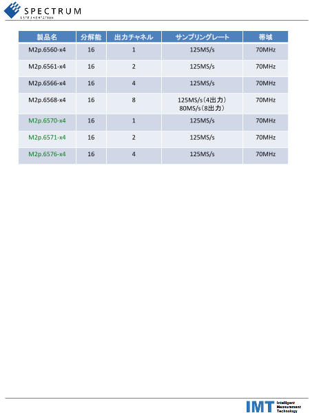
製品名 分解能 出力チャネル サンプリングレート 帯域
M2p.6560-x4 16 1 125MS/s 70MHz
M2p.6561-x4 16 2 125MS/s 70MHz
M2p.6566-x4 16 4 125MS/s 70MHz
M2p.6568-x4 16 8 125MS/s(4出力) 70MHz
80MS/s(8出力)
M2p.6570-x4 16 1 125MS/s 70MHz
M2p.6571-x4 16 2 125MS/s 70MHz
M2p.6576-x4 16 4 125MS/s 70MHz
Page3
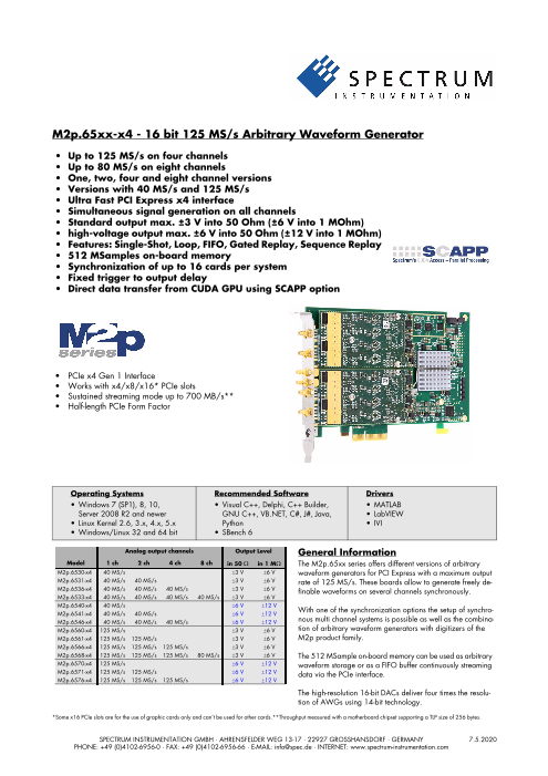
M2p.65xx-x4 - 16 bit 125 MS/s Arbitrary Waveform Generator
• Up to 125 MS/s on four channels
• Up to 80 MS/s on eight channels
• One, two, four and eight channel versions
• Versions with 40 MS/s and 125 MS/s
• Ultra Fast PCI Express x4 interface
• Simultaneous signal generation on all channels
• Standard output max. ±3 V into 50 Ohm (±6 V into 1 MOhm)
• high-voltage output max. ±6 V into 50 Ohm (±12 V into 1 MOhm)
• Features: Single-Shot, Loop, FIFO, Gated Replay, Sequence Replay
• 512 MSamples on-board memory
• Synchronization of up to 16 cards per system
• Fixed trigger to output delay
• Direct data transfer from CUDA GPU using SCAPP option
• PCIe x4 Gen 1 Interface
• Works with x4/x8/x16* PCIe slots
• Sustained streaming mode up to 700 MB/s**
• Half-length PCIe Form Factor
Operating Systems Recommended Software Drivers
• Windows 7 (SP1), 8, 10, • Visual C++, Delphi, C++ Builder, • MATLAB
Server 2008 R2 and newer GNU C++, VB.NET, C#, J#, Java, • LabVIEW
• Linux Kernel 2.6, 3.x, 4.x, 5.x Python • IVI
• Windows/Linux 32 and 64 bit • SBench 6
Analog output channels Output Level General Information
Model 1 ch 2 ch 4 ch 8 ch in 50 Ω in 1 MΩ The M2p.65xx series offers different versions of arbitrary
M2p.6530-x4 40 MS/s ±3 V ±6 V waveform generators for PCI Express with a maximum output
M2p.6531-x4 40 MS/s 40 MS/s ±3 V ±6 V rate of 125 MS/s. These boards allow to generate freely de-
M2p.6536-x4 40 MS/s 40 MS/s 40 MS/s ±3 V ±6 V finable waveforms on several channels synchronously.
M2p.6533-x4 40 MS/s 40 MS/s 40 MS/s 40 MS/s ±3 V ±6 V
M2p.6540-x4 40 MS/s ±6 V ±12 V
M2p.6541-x4 40 MS/s 40 MS/s ±6 V ±12 V With one of the synchronization options the setup of synchro-
M2p.6546-x4 40 MS/s 40 MS/s 40 MS/s ±6 V ±12 V nous multi channel systems is possible as well as the combina-
M2p.6560-x4 125 MS/s ±3 V ±6 V tion of arbitrary waveform generators with digitizers of the
M2p.6561-x4 125 MS/s 125 MS/s ±3 V ±6 V M2p product family.
M2p.6566-x4 125 MS/s 125 MS/s 125 MS/s ±3 V ±6 V
M2p.6568-x4 125 MS/s 125 MS/s 125 MS/s 80 MS/s ±3 V ±6 V The 512 MSample on-board memory can be used as arbitrary
M2p.6570-x4 125 MS/s ±6 V ±12 V waveform storage or as a FIFO buffer continuously streaming
M2p.6571-x4 125 MS/s 125 MS/s ±6 V ±12 V data via the PCIe interface.
M2p.6576-x4 125 MS/s 125 MS/s 125 MS/s ±6 V ±12 V
The high-resolution 16-bit DACs deliver four times the resolu-
tion of AWGs using 14-bit technology.
*Some x16 PCIe slots are for the use of graphic cards only and can’t be used for other cards.**Throughput measured with a motherboard chipset supporting a TLP size of 256 bytes.SPECTRUM INSTRUMENTATION GMBH · AHRENSFELDER WEG 13-17 · 22927 GROSSHANSDORF · GERMANY 7.5.2020
PHONE: +49 (0)4102-6956-0 · FAX: +49 (0)4102-6956-66 · E-MAIL: info@spec.de · INTERNET: www.spectrum-instrumentation.com
Page4
Software Support multiplexing, data conversion or FFT. All the software is based on
C/C++ and can easily be implemented, expanded and modified
Windows drivers with normal programming skills.
The cards are delivered with drivers for Windows 7, Windows 8
and Windows 10 (each 32 bit and 64 bit). Programming exam- Third-party products
ples for Visual C++, C++ Builder, LabWindows/CVI, Delphi, Visu- Spectrum supports the most popular third-party software products
al Basic, VB.NET, C#, J#, Python, Java and IVI are included. such as LabVIEW, MATLAB or LabWindows/CVI. All drivers come
with detailed documentation and working examples are included in
Linux Drivers the delivery. Support for other software packages, like VEE or Da-
All cards are delivered with full Linux support. Pre com- syLab, can also be provided on request.
piled kernel modules are included for the most common
distributions like Fedora, Suse, Ubuntu LTS or Debian. The Hardware features and options
Linux support includes SMP systems, 32 bit and 64 bit
systems, versatile programming examples for GNU C++, PCI Express x4
Python as well as the possibility to get the driver sources for your The M2p series cards use a PCI Express
own compilation. x4 Gen 1 connection. They can be used
in PCI Express x4, x8 and x16 slots with
SBench 6 hosts supporting Gen 1, Gen 2, Gen 3 or
A base license of Gen4. The maximum sustained data trans-
SBench 6, the easy- fer rate is more than 700 MByte/s (read direction) or 700 MByte/s
to-use graphical oper- (write direction) per slot. Physically supported slots that are electri-
ating software for cally connected with only x1 or x2 can also be used with the M2p
Spectrum cards, is in- series cards, but with reduced data transfer rates.
cluded in the deliv-
ery. The base license Connections
makes it is possible to The cards are equipped with SMB connectors for the an-
test the card, gener- alog signals as well as for the external trigger and clock
ate simple signals or input. In addition, there are four MMCX connectors: one
load and replay pre- multi-function output (X0) and three multi-function I/O
viously stored SBench connectors (X1, X2, X3). These multi-function connectors
6 signals. It's a valu- can be individually programmed to perform different
able tool for checking functions:
the cards perfor-
mance and assisting • Clock output (X0 only)
with the units initial setup. The cards also come with a demo license • Trigger output
for the SBench6 professional version. This license gives the user the • Status output (armed, triggered, ready, ...)
opportunity to test the additional features of the professional version • Synchronous digital inputs, being stored inside the analog data
with their hardware. The professional version contains several ad- samples
vanced measurement functions, such as FFTs and X/Y display, im- • Asynchronous I/O lines
port and export utilities as well as support for all replay modes • Logic trigger inputs
including data streaming. Data streaming allows the cards to con-
tinuously replay data and transfer it directly from the PC RAM or Singleshot output
hard disk. SBench 6 has been optimized to handle data files of sev- When singleshot output is activated the data of the on-board mem-
eral GBytes. SBench 6 runs under Windows as well as Linux (KDE ory is played exactly one time. The trigger source can be either one
and GNOME) operating systems. A test version of SBench 6 can of the external trigger inputs or the software trigger. After the first
be downloaded directly over the internet and can run the profes- trigger additional trigger events will be ignored.
sional version in a simulation mode without any hardware installed.
Existing customers can also request a demo license for the profes-
sional version from Spectrum. More details on SBench 6 can be Repeated output
found in the SBench 6 data sheet. When the repeated output mode is used the data of the on-board
memory is played continuously for a programmed number of times
or until a stop command is executed. The trigger source can be ei-
SCAPP – CUDA GPU based data processing ther one of the external trigger inputs or the software trigger. After
For applications requiring the first trigger additional trigger events will be ignored.
high performance signal
and data processing Single Restart replay
Spectrum offers SCAPP
(Spectrum’s CUDA Access When this mode is activated the data of the on-board memory will
for Parallel Processing). be replayed once after each trigger event. The trigger source can
The SCAPP SDK allows a be either the external TTL trigger or software trigger.
direct link between Spec-
trum digitizers, AWGs or FIFO mode
Digital Data Acquisition The FIFO or streaming mode is designed for continuous data trans-
Cards and CUDA based GPU cards. Once in the GPU users can fer between the card and the PC memory. When mounted in a PCI
harness the processing power of the GPU’s multiple (up to 5000) Express x4 Gen 1 interface read streaming speeds of up to 700
processing cores and large (up to 24 GB) memories. SCAPP uses MByte/s are possible. The control of the data stream is done auto-
an RDMA (Linux only) process to send data at the full PCIe transfer matically by the driver on interrupt request basis. The complete in-
speed to and from the GPU card. The SDK includes a set of exam- stalled onboard memory is used to buffer the data, making the
ples for interaction between the Spectrum card and the GPU card continuous streaming process extremely reliable.
and another set of CUDA parallel processing examples with easy
building blocks for basic functions like filtering, averaging, data de-
Page5
Multiple Replay Independent of the number of boards
The Multiple Replay mode al- there is no phase delay between the
lows the fast output genera- channels. The Star-Hub distributes trigger
tion on several trigger events and clock information between all
without restarting the hard- boards. As a result all connected boards
ware. With this option very are running with the same clock and the
fast repetition rates can be same trigger. All trigger sources can be
achieved. The on-board memory is divided into several segments of combined with OR/AND. For digitizers
the same size. Each segment can contain different data which will that means all channels of all cards to be
then be played with the occurrence of each trigger event. trigger source at the same time.
Gated Replay Multi-Purpose I/O 4 Standard + 16 Option
The Gated Sampling mode al-
lows data replay controlled As standard each card has 4 multi-pur-pose I/O lines (3 x I/O and 1 x Output).
by an external gate signal. As an option a piggy-back module carries
Data is only replayed if the additional 16 mutli-purpose I/O lines
gate signal has attained a making up to 19 digtal inputs or 20 digi-
programmed level. tal outputs.
This option is available with SMB connec-
Sequence Mode tors or with FX/2 connector for flat-ribbon
cable, with pin-compatibility with previous
The sequence hardware versions.
mode allows to
split the card All I/O lines can be used for synchronous digital data acquisition
memory into sev- (digitizer), synchronous digital data output/marker output (AWG),
eral data segments of different length. These data segments are asynchronous digital I/O, can carry additional status information
chained up in a user chosen order using an additional sequence or can be used as trigger inputs
memory. In this sequence memory the number of loops for each seg-
ment can be programmed and trigger conditions can be defined to
proceed from segment to segment. Using the sequence mode it is
also possible to switch between replay waveforms by a simple soft-
ware command or to redefine waveform data for segments simulta-
neously while other segments are being replayed. All trigger-
related and software-command-related functions are only working
on single cards, not on star-hub-synchrnonized cards.
External trigger input
All boards can be triggered using an external analog or digital sig-
nal. The external trigger input has one comparator that can be used
for standard edge and level triggers.
External clock input and output
Using a dedicated connector a sampling clock can be fed in from
an external system. Additionally it’s also possible to output the in-
ternally used sampling clock on a separate connector to synchro-
nize external equipment to this clock.
Reference clock
The option to use a precise
external reference clock
(typically 10 MHz) is nec-
essary to synchronize the
instrument for high-quality
measurements with external equipment (like a signal source). It’s
also possible to enhance the stability of the sampling clock in this
way. The driver automatically generates the requested sampling
clock from the fed in reference clock.
Star-Hub
The Star-Hub is an additional mod-
ule allowing the phase stable syn-
chronization of up to 16 boards in
one system. Two versions are avail-
able: one with up to 6 cards and
the large version supports up to 16
cards in one system. Both versions
can be mounted in two different
ways, to either extend the cards
length to ¾ PCIe length occupying one slot, or extend its width to
two slots whilst keeping the ½ PCIe length.
Page6
Technical Data
Analog Outputs
Resolution 16 bit
D/A Interpolation no interpolation
Output amplitude software programmable 653x and 656x: ±1 mV up to ±3 V in 1 mV steps into 50 Ω termination
(resulting in ±2 mV up to ±6 V in 2mV steps into high impedance loads)
654x and 657x: ±1 mV up to ±6 V in 1 mV steps into 50 Ω termination
(resulting in ±2 mV up to ±12 V in 2mV steps into high impedance loads)
Note: Gain values below ±300 mV into 50 Ω are reduced by digital scaling of the samples
Output Amplifier Path Selection automatically by driver Low Power path: Selected Gain of ±1 mV to ±960 mV (into 50 Ω)
High Power path: 653x and 656x: Selected Gain of ±940 mV to ±3 V (into 50 Ω)
654x and 657x: Selected Gain of ±940 mV to ±6 V (into 50 Ω)
Output Amplifier Setting Hysteresis automatically by driver 940 mV to 960 mV (if output is using low power path it will switch to high power path at 960 mV. If
output is using high power path it will switch to low power path at 940 mV)
Output amplifier path switching time 1.2 ms (output disabled while switching)
Output offset software programmable Low Power path: ±960 mV in 1 mV steps into 50 Ω (±1920 mV in 2 mV steps into 1 MΩ)
High Power path: 653x and 656x: ±3 V in 1 mV steps into 50 Ω (±6V in 2 mV steps into 1 MΩ)
654x and 657x: ±6 V in 1 mV steps into 50 Ω (±12V in 2 mV steps into 1 MΩ)
Filters software programmable One of 4 different filters (refer to „Bandwidth and Filters“ section)
DAC Differential non linearity (DNL) DAC only ±2.0 LSB typical
DAC Integral non linearity (INL) DAC only ±4.0 LSB typical
Output resistance 50 Ω
Minimum output load 653x and 656x: 0 Ω (short circuit safe by design)
654x and 657x: 50 Ω (short circuit safe by hardware supervisor, outputs will turn off)
Max output swing in 50 Ω 653x and 656x: ±3.0 V (offset + amplitude)
654x and 657x: ±6.0 V (offset + amplitude)
Max output swing in 1 MΩ 653x and 656x: ±6.0 V (offset + amplitude)
654x and 657x: ±12.0 V (offset + amplitude)
Slewrate (using Filter 0) Low power path (0 to 900 mV): 250 mV/ns
653x and 656x: High power path (0 to 3000 mV): 850 mV/ns
654x and 657x: High power path (0 to 6000 mV): TBD
Crosstalk @ 1 MHz signal ±3 V 1 to 4 ch standard AWG 95 dB (M2p.6530, M2p.6531, M2p.6536, M2p.6560, M2p.6561, M2p.6566)
Crosstalk @ 1 MHz signal ±3 V 8 channel AWG 84 dB (M2p.6533, M2p.6568)
Crosstalk @ 1 MHz signal ±6 V 1 to 4 ch high-voltage AWG 99 dB (M2p.6540, M2p.6541, M2p.6546, M2p.6540, M2p.6541, M2p.6546)
Output accuracy ±1 mV ±0.5 % of programmed output amplitude ±0.1 % of programmed output offset
Trigger
Available trigger modes software programmable External, Software, Pulse, Or/And, Delay
Trigger edge software programmable Rising edge, falling edge or both edges
Trigger pulse width software programmable 0 to [4G - 1] samples in steps of 1 sample
Trigger delay software programmable 0 to [4G - 1] samples in steps of 1 samples
Trigger holdoff (for Multi, Gate) software programmable 0 to [4G - 1] samples in steps of 1 samples
Multi, Gate: re-arming time < 24 samples (+ programmed holdoff)
Trigger to Output Delay 63 sample clocks + 7 ns
Memory depth software programmable 16 up to [installed memory / number of active channels] samples in steps of 8
Multiple Replay segment size software programmable 8 up to [installed memory / number of active channels] samples in steps of 8
External trigger accuracy 1 sample
External trigger Ext X1, X2, X3
External trigger type Single level comparator 3.3V LVTTL logic inputs
External trigger impedance software programmable 50 Ω / 5 kΩ For electrical specifications refer to
External trigger input level ±5 V (5 kΩ), ±2.5 V (50 Ω), „Multi Purpose I/O lines“ section.
External trigger over voltage protection ±20 V (5 kΩ), 5 Vrms (50 Ω)
External trigger sensitivity 200 mVpp
(minimum required signal swing)
External trigger level software programmable ±5 V in steps of 1 mV
External trigger bandwidth 50 Ω DC to 400 MHz n.a.
5 kΩ DC to 300 MHz DC to 125 MHz
Minimum external trigger pulse width ≥ 2 samples ≥ 2 samples
Page7
Multi Purpose I/O lines
Number of multi purpose output lines one, named X0
Number of multi purpose input/output lines three, named X1, X2, X3
Multi Purpose line X0 X1, X2, X3
Input: available signal types software programmable n.a. Asynchronous Digital-In, Logic trigger
Input: signal levels n.a. 3.3 V LVTTL
Input: impedance n.a. 10 kΩ to 3.3 V
Input: maximum voltage level n.a. -0.5 V to +4.0 V
Input: maximum bandwidth n.a. 125 MHz
Output: available signal types software programmable Run-, Arm-, Trigger-Output, Run-, Arm-, Trigger-Output,
Marker-Output, Synchronous Digital-Out, Marker-Output, Synchronous Digital-Out,
Asynchronous Digital-Out Asynchronous Digital-Out,
ADC Clock Output,
Output: impedance 50 Ω
Output: drive strength Capable of driving 50 Ω loads, maximum drive strength ±48 mA
Output: type / signal levels 3.3V LVTTL, TTL compatible for high impedance loads
Output: update rate (synchronous modes) sampling clock
Option M2p.xxxx-DigFX2 / M2p.xxxx-DigSMB common
Input: signal levels 3.3 V LVTTL
Input: impedance 10 kΩ to 3.3 V
Input: maximum voltage level -0.5 V to +4.0 V
Input: maximum bandwidth 125 MHz
Input: available signal types software programmable Synchronous Digital-In (M2p.59xx only), Asynchronous Digital-In
Output: available signal types software programmable Run-, Arm-, Trigger-Output, Synchronous Digital-Out (M2p.65xx only), Asynchronous Digital-Out
Output: update rate (synchronous modes) sampling clock
Output: type / signal levels 3.3V LVTTL, TTL compatible for high impedance loads
Output: impedance 50 Ω
Output: drive strength Capable of driving 50 Ω loads, maximum drive strength ±48 mA
Option M2p.xxxx-DigFX2 specific
Number of additional multi-purpose I/O lines 16 (X4 to X19)
Card width with installed option Requires one additional slot left of the main card’s bracket, on „solder side“ of the PCIe card
Connector 1 x 40 pole half pitch (Hirose FX2 series, one adapter cable to IDC connector in standard
2.54mm pitch included (Cab-d40-xx-xx).
4 x SMB male, (jumper selectable between FX2/SMB for: X12, X13, X18 and X19))
Connector on card: Hirose FX2B-40PA-1.27DSL
Flat ribbon cable connector: Hirose FX2B-40SA-1.27R
Output: impedance FX2: 90 Ω , SMB: 50 Ω
Output: drive strength Capable of driving 90 Ω loads (FX2), 50 Ω loads (SMB), maximum drive strength ±48 mA
Compatibility Pinning compatible with M2i.xxxx-dig option and M2i.70xx connectors
Option M2p.xxxx-DigSMB specific
Number of additional multi purpose I/O lines 16 (X4 to X19)
Card width with installed option Requires one additional slot left of the main card’s bracket, on „solder side“ of the PCIe card
Connectors on bracket 10 x SMB male (X4 to X13)
Internal connectors 6 x SMB male (X14 to X19)
Output: impedance 50 Ω
Output: drive strength Capable of driving 50 Ω loads, maximum drive strength ±48 mA
Sequence Replay Mode
Number of sequence steps software programmable 1 up to 4096 (sequence steps can be overloaded at runtime)
Number of memory segments software programmable 2 up to 64k (segment data can be overloaded at runtime)
Minimum segment size software programmable 32 samples in steps of 8 samples.
Maximum segment size software programmable 512 MS / active channels / number of sequence segments (round up to the next power of two)
Loop Count software programmable 1 to (1M - 1) loops
Sequence Step Commands software programmable Loop for #Loops, Next, Loop until Trigger, End Sequence
Special Commands software programmable Data Overload at runtime, sequence steps overload at runtime,
readout current replayed sequence step
Limitations for synchronized products Software commands changing the sequence as well as „Loop until trigger“ are not synchronized
between cards. This also applies to multiple AWG modules in a generatorNETBOX.
Page8
Clock
Clock Modes software programmable internal PLL, external clock, external reference clock, sync
Internal clock range (PLL mode) software programmable see „Clock Limitations“ table below
Internal clock accuracy after warm-up ≤ ±1.0 ppm (at time of calibration in production)
Internal clock aging ≤ ±0.5 ppm / year
PLL clock setup granularity (int. or ext. reference) 1 Hz
External reference clock range software programmable 128 kHz up to 125 MHz
Direct external clock to internal clock delay 4.3 ns
Direct external clock range see „Clock Limitations and Bandwidth“ table below
External clock type Single level comparator
External clock input level ±5 V (5 kΩ), ±2.5 V (50 Ω),
External clock input impedance software programmable 50 Ω / 5 kΩ
External clock over voltage protection ±20 V (5 kΩ), 5 Vrms (50 Ω)
External clock sensitivity 200 mVpp
(minimum required signal swing)
External clock level software programmable ±5 V in steps of 1mV
External clock edge rising edge used
External reference clock input duty cycle 45% - 55%
Clock output electrical specification Available via Multi Purpose output X0. Refer to „Multi Purpose I/O lines“ section.
Synchronization clock multiplier „N“ for software programmable N being a multiplier (1, 2, 3, 4, 5, ... Max) of the card with the currently slowest sampling clock.
different clocks on synchronized cards The card maximum (see „Clock Limitations and Bandwidth“ table below) must not be exceeded.
Channel to channel skew on one card < 200 ps (typical)
Skew between star-hub synchronized cards TBD
Connectors
Analog SMB male (one for each single-ended input/output) Cable-Type: Cab-3f-xx-xx
Trigger Input SMB male Cable-Type: Cab-3f-xx-xx
Clock Input SMB male Cable-Type: Cab-3f-xx-xx
Standard Multi Purpose I/O MMCX female (4 lines) Cable-Type: Cab-1m-xx-xx
Option M2p.xxxx-DigSMB on extra bracket SMB male Cable-Type: Cab-3f-xx-xx
Option M2p.xxxx.DigFX2 on extra bracket 40-pole half pitch (Hirose FX2) Cable-Type: Cab-d40-xx-xx
Environmental and Physical Details
Dimension (Single Card) type 8 channel AWG or L x H x W: 168 mm (½ PCIe length) x 107 mm x 30 mm. Requires one additional slot right of
M2p.65x3, M2p.65x8, M2p.654x or M2p.657x High power AWG the main card’s bracket, on „component side“ of the PCIe card.
Dimension (all other single cards) L x H x W: 168 mm (½ PCIe length) x 107 mm x 20 mm (single slot width)
Dimension (with -SH6tm or -SH16tm installed) Extends W by 1 slot right of the main card’s bracket, on „component side“ of the PCIe card.
Dimension (with -SH6ex or -SH16ex installed) Extends L to 245 mm (¾ PCIe length) at the back of the PCIe card
Dimension (with -DigSMB or -DigFX2 installed) Extends W by 1 slot left of the main card’s bracket, on „solder side“ of the PCIe card.
Weight (M2p.59xx series) maximum 215 g
Weight (M2p.65x0, M2p.65x1, M2p.65x6 series) maximum 195 g
Weight (M2p.65x3, 65x8, 654x, 657x series) maximum 305 g
Weight (Star-Hub Option -SH6ex, -SH6tm) including 6 sync cables 65 g
Weight (Star-Hub Option -SH16ex, -SH16tm) including 16 sync cables 90 g
Weight (Option -DigSMB) 50 g
Weight (Option -DigFX2) 60 g
Warm up time 10 minutes
Operating temperature 0 °C to 40 °C
Storage temperature -10 °C to 70 °C
Humidity 10% to 90%
PCI Express specific details
PCIe slot type x4, Generation 1
PCIe slot compatibility (physical) x4, x8, x16
PCIe slot compatibility (electrical) x1, x2, x4, x8, x16 with Generation 1, Generation 2, Generation 3, Generation 4
Sustained streaming mode > 700 MB/s (measured with a chipset supporting a TLP size of 256 bytes, using PCIe x4 Gen1)
(Card-to-System: M2p.59xx)
Sustained streaming mode > 700 MB/s (measured with a chipset supporting a TLP size of 256 bytes, using PCIe x4 Gen1)
(System-to-Card: M2p.65xx)
Certification, Compliance, Warranty
EMC Immunity Compliant with CE Mark
EMC Emission Compliant with CE Mark
Product warranty 5 years starting with the day of delivery
Software and firmware updates Life-time, free of charge
Page9
Power Consumption
3.3V 12 V Total
M2p.6530-x4 Typical values: All channels activated, Sample rate: 40 MSps 0.1 A 0.8 A 10 W
M2p.6531-x4 Output signal: 10 MHz sine wave, Output level: +/- 3.0 V into 50 Ω load 0.1 A 0.9 A 11 W
M2p.6536-x4 0.1 A 1.2 A 15 W
M2p.6533-x4 0.1 A 1.8 A 23 W
M2p.6540-x4 Typical values: All channels activated, Sample rate: 40 MSps 0.1 A 1.0 A 13 W
M2p.6541-x4 Output signal: 10 MHz sine wave, Output level: +/- 6.0 V into 50 Ω load 0.1 A 1.4 A 17 W
M2p.6546-x4 0.1 A 2.2 A 27 W
M2p.6560-x4 Typical values: All channels activated, Sample rate: 125 MSps 0.1 A 0.8 A 10 W
M2p.6561-x4 Output signal: 10 MHz sine wave, Output level: +/- 3.0 V into 50 Ω load 0.1 A 0.9 A 11 W
M2p.6566-x4 0.1 A 1.2 A 15 W
M2p.6568-x4 0.1 A 1.9 A 23 W
M2p.6570-x4 Typical values: All channels activated, Sample rate: 125 MSps 0.1 A 1.0 A 13 W
M2p.6571-x4 Output signal: 10 MHz sine wave, Output level: +/- 6.0 V into 50 Ω load 0.1 A 1.4 A 17 W
M2p.6576-x4 0.1 A 2.2 A 27 W
MTBF
MTBF TBD hours
Clock Limitations
M2p.653x M2p.656x
DNx.653-xx DNx.656-xx
M2p.654x M2p.657x
DNx.654-xx DNx.657-xx
max internal clock (non-synchronized cards) 40 MS/s 125 MS/s
min internal clock (non-synchronized cards) 1 kS/s 1 kS/s
max internal clock (cards synchronized via star-hub) 40 MS/s 125 MS/s
min internal clock (cards synchronized via star-hub) 128 kS/s 128 kS/s
max direct external clock 40 MS/s 125 MS/s
min direct external clock DC DC
min direct external clock LOW time 4 ns 4 ns
min direct external clock HIGH time 4 ns 4 ns
Bandwidth and Filters
Filter - 3dB bandwidth Filter characteristic
Analog bandwidth does not include Sinc response of DAC Filter 0 70 MHz third-order Butterworth
Filter 1 20 MHz fifth-order Butterworth
Filter 2 5 MHz fourth-order Bessel
Filter 3 1 MHz fourth-order Bessel
Page10
Dynamic Parameters
M2p.653x/DNx.653-xx
Test - Samplerate 40 MS/s 40 MS/s
Output Frequency 800 kHz 4 MHz
Output Level in 50 Ω ±900mV ±3000mV ±900mV ±3000mV
Used Filter 1 MHz 5 MHz
NSD (typ) -142 dBm/Hz -132 dBm/Hz -142 dBm/Hz -132 dBm/Hz
SNR (typ) 90.7 dB 91.1 dB 83.7 dB 84.1 dB
THD (typ) -74.0 dB -74.0 dB -70.5 dB -70.5 dB
SINAD (typ) 73.9 dB 73.9 dB 69.8 dB 69.8 dB
SFDR (typ), excl harm. 97.0 dB 95.0 dB 88.0 dB 88.0 dB
ENOB (SINAD) 12.0 12.0 11.3 11.3
ENOB (SNR) 14.7 14.8 13.5 13.6
M2p.654x/DNx.654-xx
Test - Samplerate 40 MS/s 40 MS/s
Output Frequency 800 kHz 4 MHz
Output Level in 50 Ω ±900mV ±6000mV ±900mV ±6000mV
Used Filter 1 MHz 5 MHz
NSD (typ) -138 dBm/Hz -129 dBm/Hz -142 dBm/Hz -126 dBm/Hz
SNR (typ) 86.7 dB 88.1 dB 83.7 dB 84.2 dB
THD (typ) -74.0 dB -74.0 dB -74.0 dB -74.0 dB
SINAD (typ) 73.8 dB 73.8 dB 73.6 dB 73.6 dB
SFDR (typ), excl harm.
ENOB (SINAD) 12.0 12.0 11.9 11.9
ENOB (SNR) 14.1 14.3 13.6 13.7
M2p.656x/DNx.656-xx
Test - Samplerate 125 MS/s 125 MS/s 125 MS/s
Output Frequency 800 kHz 4 MHz 16 MHz
Used Filter 1 MHz 5 MHz 20 MHz
Output Level in 50 Ω ±900mV ±3000mV ±900mV ±3000mV ±900mV ±3000mV
NSD (typ) -142 dBm/Hz -132 dBm/Hz -142 dBm/Hz -132 dBm/Hz -142 dBm/Hz -132 dBm/Hz
SNR (typ) 90.7 dB 91.1 dB 83.7 dB 84.1 dB 77.7 dB 78.1 dB
THD (typ) -74.0 dB -74.0 dB -70.5 dB -70.5 dB -66.0 dB -61.9 dB
SINAD (typ) 73.9 dB 73.9 dB 69.8 dB 69.8 dB 65.7 dB 60.9 dB
SFDR (typ), excl harm. 97.0 dB 95.0 dB 88.0 dB 88.0 dB 90.0 dB 89.0 dB
ENOB (SINAD) 12.0 12.0 11.3 11.3 10.6 9.8
ENOB (SNR) 14.7 14.8 13.5 13.6 12.5 12.6
M2p.657x/DNx.657-xx
Test - Samplerate 125 MS/s 125 MS/s 125 MS/s
Output Frequency 800 kHz 4 MHz 16 MHz
Used Filter 1 MHz 5 MHz 20 MHz
Output Level in 50 Ω ±900mV ±6000mV ±900mV ±6000mV ±900mV ±6000mV
NSD (typ) -138 dBm/Hz -129 dBm/Hz -142 dBm/Hz -126 dBm/Hz -142 dBm/Hz -127 dBm/Hz
SNR (typ) 86.7 dB 88.1 dB 83.7 dB 84.2 dB 77.7 dB 79.1 dB
THD (typ) -74.0 dB -74.0 dB -74.0 dB -74.0 dB -70.5 dB -63.1 dB
SINAD (typ) 73.8 dB 73.8 dB 73.6 dB 73.6 dB 69.7 dB 63.0 dB
SFDR (typ), excl harm.
ENOB (SINAD) 12.0 12.0 11.9 11.9 11.3 10.2
ENOB (SNR) 14.1 14.3 13.6 13.7 12.6 12.8
THD and SFDR are measured at the given output level and 50 Ohm termination with a high resolution M3i.4860/M4i.4450-x8 data acquisition card and are calculated from the spec-
trum. Noise Spectral Density is measured with built-in calculation from an HP E4401B Spectrum Analyzer. All available D/A channels are activated for the tests. SNR and SFDR figures
may differ depending on the quality of the used PC. NSD = Noise Spectral Density, THD = Total Harmonic Distortion, SFDR = Spurious Free Dynamic Range.
Page11
Hardware block diagram
Page12
Order Information
The card is delivered with 512 MSample on-board memory and supports standard replay, FIFO replay (streaming), Multiple Replay, Gated
Replay, Continuous Replay (Loop), Single-Restart as well as Sequence. Operating system drivers for Windows/Linux 32 bit and 64 bit, ex-
amples for C/C++, LabVIEW (Windows), MATLAB (Windows and Linux), IVI, .NET, Delphi, Java, Python and a Base license of the measure-
ment software SBench 6 are included.
Adapter cables are not included. Please order separately!
PCI Express x4 Order no. D/A Resolution Standard mem Single-Ended Outputs Output Level
Standard Version M2p.6530-x4 16 Bit 512 MSample 1 channel 40 MS/s ±3 V (50Ω) or ±6 V (1 MΩ)
with ±3V output in 50Ω M2p.6531-x4 16 Bit 512 MSample 2 channels 40 MS/s ±3 V (50Ω) or ±6 V (1 MΩ)
M2p.6536-x4 16 Bit 512 MSample 4 channels 40 MS/s ±3 V (50Ω) or ±6 V (1 MΩ)
M2p.6533-x4 16 Bit 512 MSample 8 channels 40 MS/s ±3 V (50Ω) or ±6 V (1 MΩ)
M2p.6560-x4 16 Bit 512 MSample 1 channel 125 MS/s ±3 V (50Ω) or ±6 V (1 MΩ)
M2p.6561-x4 16 Bit 512 MSample 2 channels 125 MS/s ±3 V (50Ω) or ±6 V (1 MΩ)
M2p.6566-x4 16 Bit 512 MSample 4 channels 125 MS/s ±3 V (50Ω) or ±6 V (1 MΩ)
M2p.6568-x4 16 Bit 512 MSample 4 channels 125 MS/s ±3 V (50Ω) or ±6 V (1 MΩ)
8 channels 80 MS/s
PCI Express x4 Order no. D/A Resolution Standard mem Single-Ended Outputs Output Level
High Voltage Version M2p.6540-x4 16 Bit 512 MSample 1 channel 40 MS/s ±6 V (50Ω) or ±12 V (1 MΩ)
with ±6V output in 50Ω M2p.6541-x4 16 Bit 512 MSample 2 channels 40 MS/s ±6 V (50Ω) or ±12 V (1 MΩ)
M2p.6546-x4 16 Bit 512 MSample 4 channels 40 MS/s ±6 V (50Ω) or ±12 V (1 MΩ)
M2p.6570-x4 16 Bit 512 MSample 1 channel 125 MS/s ±6 V (50Ω) or ±12 V (1 MΩ)
M2p.6571-x4 16 Bit 512 MSample 2 channels 125 MS/s ±6 V (50Ω) or ±12 V (1 MΩ)
M2p.6576-x4 16 Bit 512 MSample 4 channels 125 MS/s ±6 V (50Ω) or ±12 V (1 MΩ)
Options Order no. Option
M2p.xxxx-SH6ex (1) Synchronization Star-Hub for up to 6 cards incl. cables, only one slot width, card length 245 mm
M2p.xxxx-SH6tm (1) Synchronization Star-Hub for up to 6 cards incl. cables, two slots width, standard card length
M2p.xxxx-SH16ex (1) Synchronization Star-Hub for up to 16 cards incl. cables, only one slot width, card length 245 mm
M2p.xxxx-SH16tm (1) Synchronization Star-Hub for up to 16 cards incl. cables, two slots width, standard card length
M2p.xxxx-DigFX2 16 additional multi-purpose I/O lines on separate slot bracket, FX2 connector (incl. Cab-d40-idc-100)
M2p.xxxx-DigSMB 16 additional multi-purpose I/O lines, 10 on separate slot bracket, 6 internal connectors
M2p-upgrade Upgrade for M2p.xxxx: Later installation of options Star-Hub or Dig.
Services Order no.
Recal Recalibration at Spectrum incl. calibration protocol
Cables Order no.
for Connections Length to BNC male to BNC female to SMA male to SMA female to SMB female
Analog/Clock-In/Trig-In 80 cm Cab-3f-9m-80 Cab-3f-9f-80 Cab-3f-3mA-80 Cab-3f-3fA-80 Cab-3f-3f-80
/Option DigSMB
Analog/Clock-In/Trig-In 200 cm Cab-3f-9m-200 Cab-3f-9f-200 Cab-3f-3mA-200 Cab-3f-3fA-200 Cab-3f-3f-200
/Option DigSMB
Probes (short) 5 cm Cab-3f-9f-5
Clk-Out/Trig-Out/Extra 80 cm Cab-1m-9m-80 Cab-1m-9f-80 Cab-1m-3mA-80 Cab-1m-3fA-80 Cab-1m-3f-80
Clk-Out/Trig-Out/Extra 200 cm Cab-1m-9m-200 Cab-1m-9f200 Cab-1m-3mA-200 Cab-1m-3fA-200 Cab-1m-3f-200
Information The standard adapter cables are based on RG174 cables and have a nominal attenuation of 0.3 dB/m at 100 MHz.
to 2x20 pole IDC to 40 pole FX2
M2p.xxxx-DigFX2 100 cm Cab-d40-idc-100 Cab-d40-d40-100
Software SBench6 Order no.
SBench6 Base version included in delivery. Supports standard mode for one card.
SBench6-Pro Professional version for one card: FIFO mode, export/import, calculation functions
SBench6-Multi Option multiple cards: Needs SBench6-Pro. Handles multiple synchronized cards in one system.
Volume Licenses Please ask Spectrum for details.
Software Options Order no.
SPc-RServer Remote Server Software Package - LAN remote access for M2i/M3i/M4i/M4x/M2p cards
SPc-SCAPP Spectrum’s CUDA Access for Parallel Processing - SDK for direct data transfer between Spectrum card
and CUDA GPU. Includes RDMA activation and examples. Signed NDA needed for access.
(1) : Just one of the options can be installed on a card at a time.
(2) : Third party product with warranty differing from our export conditions. No volume rebate possible.
Technical changes and printing errors possible
SBench, digitizerNETBOX and generatorNETBOX are registered trademarks of Spectrum Instrumentation GmbH. Microsoft, Visual C++, Windows, Windows 98, Windows NT, Window 2000, Windows XP, Windows Vista,
Windows 7, Windows 8 and Windows 10 are trademarks/registered trademarks of Microsoft Corporation. LabVIEW, DASYLab, Diadem and LabWindows/CVI are trademarks/registered trademarks of National Instruments
Corporation. MATLAB is a trademark/registered trademark of The Mathworks, Inc. Delphi and C++Builder are trademarks/registered trademarks of Embarcadero Technologies, Inc. Keysight VEE, VEE Pro and VEE OneLab
are trademarks/registered trademarks of Keysight Technologies, Inc. FlexPro is a registered trademark of Weisang GmbH & Co. KG. PCIe, PCI Express and PCI-X and PCI-SIG are trademarks of PCI-SIG. LXI is a registered
trademark of the LXI Consortium. PICMG and CompactPCI are trademarks of the PCI Industrial Computation Manufacturers Group. Oracle and Java are registered trademarks of Oracle and/or its affiliates. Intel and Intel Core
i3, Core i5, Core i7, Core i9 and Xeon are trademarks and/or registered trademarks of Intel Corporation. AMD, Opteron, Sempron, Phenom, FX, Ryzen and EPYC are trademarks and/or registered trademarks of Advanced
Micro Devices. NVIDIA, CUDA, GeForce, Quadro and Tesla are trademarks/registered trademarks of NVIDIA Corporation.