


CMOS type Micro Laser Distance Sensor HG-C / IO-Link Compatible, High-level Self-diagnostic Type HG-C10000L SERIES
Product Catalog
Document Information
| Document Title | CMOS type Micro Laser Distance Sensor HG-C / IO-Link Compatible, High-level Self-diagnostic Type HG-C10000L SERIES |
|---|---|
| Document Type | Product Catalog |
| File size | 8Mb |
| Category | |
| Company | Panasonic Industry Co., Ltd. (Documents List) |
Documents related to this company


Product Catalog
Panasonic Industry Co., Ltd.


Document Contents
Page1
表 4(210 ミリ) 表 1(208 ミリ) p2(194 ミリ)
M I C R O L A S E R D I S T A N C E S E N S O R
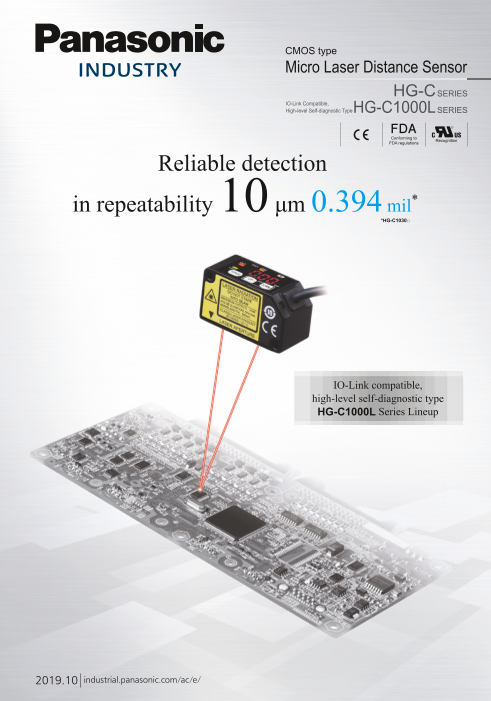
CMOS type
Micro Laser Distance Sensor
HG-CSERIES
IO-Link Compatible,
High-level Self-diagnostic Type HG-C1000LSERIES Repeatability Dimensions Inflection resistant cable
10 μm 0.394 mil W20 × H44 × D25 mm HG-C1□0(-P)
Conforming to Recognition *HG-C1030□ W0.787 × H1.732 × D0.984 in are adopted.
FDA regulations
Reliable detection 600 mm 23.622 in
in repeatability 10 μm 0.394 mil* 400 mm 15.748 in
*HG-C1030□
Measurement center distance: 400 mm 15.748 in 280 mm 11.024 in
Measurement range: ±200 mm 7.874 in
200 mm 7.874 in
135 mm 5.315 in
120 mm 4.724 in
Measurement center distance: 200 mm 7.874 in 100 mm 3.937 in
65 mm 2.559 in
Measurement range: ±80 mm 3.150 in 50 mm 1.969 in 35 mm 1.378 in
30 mm 1.181 in
25 mm 0.984 in
0 mm
Measurement center distance: 100 mm 3.937 in
Measurement range: ±35 mm 1.378 in
Measurement center distance: 50 mm 1.969 in
Measurement range: ±15 mm 0.591 in
IO-Link compatible,
high-level self-diagnostic type
HG-C1000L Series Lineup Measurement center distance: 30 mm 1.181 in HG-C1400□
Measurement range: ±5mm 0.197 in
HG-C1200□
HG-C1100□
HG-C1050□
HG-C1030□
2019.10 industrial.panasonic.com/ac/e/
2
Page2
表 4(210 ミリ) 表 1(208 ミリ) p2(194 ミリ)
M I C R O L A S E R D I S T A N C E S E N S O R
CMOS type
Micro Laser Distance Sensor
HG-CSERIES
IO-Link Compatible,
High-level Self-diagnostic Type HG-C1000LSERIES Repeatability Dimensions Inflection resistant cable
10 μm 0.394 mil W20 × H44 × D25 mm HG-C1□0(-P)
Conforming to Recognition *HG-C1030□ W0.787 × H1.732 × D0.984 in are adopted.
FDA regulations
Reliable detection 600 mm 23.622 in
in repeatability 10 μm 0.394 mil* 400 mm 15.748 in
*HG-C1030□
Measurement center distance: 400 mm 15.748 in 280 mm 11.024 in
Measurement range: ±200 mm 7.874 in
200 mm 7.874 in
135 mm 5.315 in
120 mm 4.724 in
Measurement center distance: 200 mm 7.874 in 100 mm 3.937 in
65 mm 2.559 in
Measurement range: ±80 mm 3.150 in 50 mm 1.969 in 35 mm 1.378 in
30 mm 1.181 in
25 mm 0.984 in
0 mm
Measurement center distance: 100 mm 3.937 in
Measurement range: ±35 mm 1.378 in
Measurement center distance: 50 mm 1.969 in
Measurement range: ±15 mm 0.591 in
IO-Link compatible,
high-level self-diagnostic type
HG-C1000L Series Lineup Measurement center distance: 30 mm 1.181 in HG-C1400□
Measurement range: ±5mm 0.197 in
HG-C1200□
HG-C1100□
HG-C1050□
HG-C1030□
Item Model No. HG-C1030□ HG-C1050□ HG-C1100□ HG-C1200□ HG-C1400□
Measurement center distance 30 mm 1.181 in 50 mm 1.969 in 100 mm 3.937 in 200 mm 7.874 in 400 mm 15.748 in
Measurement range ±5 mm 0.197 in ±15 mm 0.591 in ±35 mm 1.378 in ±80 mm 3.150 in ±200 mm 7.874 in
Beam diameter ø50 μm 1.969 mil ø70 μm 2.756 mil ø120 μm 4.724 mil ø300 μm 11.811 mil ø500 μm 19.685 mil
approx. approx. approx. approx. approx.
300 μm 11.811 mil
(Measuring distance 200 to 400 mm
Repeatability 10 μm 30 μm 70 μm 200 μm 7.874 to 15.748 in)
0.394 mil 1.181 mil 2.756 mil 7.874 mil 800 μm 31.496 mil
(Measuring distance 400 to 600 mm
15.748 to 23.622 in)
2019.10 industrial.panasonic.com/ac/e/
2
Page3
HG-C_3_CC2019_144
p3(194 ミリ) p4(208 ミリ) p5(210 ミリ)
M I C R O L A S E R D I S T A N C E S E N S O R HG-C SERIES
Compact Overwhelmingly stable
The smallest CMOS laser sensor in the industry* Precise measurements on the order of 1/100 mm 0.0003 inch*
*Based on research conducted by our company as of August 2019 *HG-C1030□
Indicates real measurements Compact and light-weight Long distance measurement Excellent level detection performance
Linearity: ±0.1% F.S. W20 × H44 × D25 mm W0 .787 × H1.732 × D0.984 in, Measurement center distance: 400 mm 15.748 in *HG-C1400□, Repeatability: 10 μm 0.394 mil *HG-C1030□
*HG-C1030(-P) / HG-C1050(-P) / HG-C1100(-P) 35 g approx. (excluding the cable) *HG-C1□0(-P) 200 mm 7.874 in *HG-C1200□
Measuring the hoop slack Measuring the insertion Controlling the dispenser Controlling the mounter Detecting on-vehicle seats Judging front or back of Detecting warpage of a circuit board Checking for overlapped Judging front or back of cover
depth of an actuator head height head height cover of cast parts lead frames of electric parts
Measuring the thickness Measuring the thickness of a part Controlling the parallel Installable on a food packaging Measurement of a remaining Detecting parts through a Checking for presence of packing Detecting a seam (overlap) of
of a panel link robot height line where water splashes (IP67) functional sheet viewing port functional sheet
Connected
to PLCs
Connected to PLCs
Remove water droplets on detection surface to
achieve correct measurement.
Equipped with 0 to 5 V analog output The value can be
measured with a distance • Linearity: ±0.1% F.S.* A new optical system An aluminum die-cast casing
and 4 to 20 mA analog current output HG-C1□0(-P) • Temperature characteristics: 0.03%F.S./°C with a built-in mirror protects from strain and heat Fitted with a precise CMOS image sensor and an original algorithm
measurement sensor.
*HG-C1030(-P)/ HG-C1050(-P)/ HG-C1100(-P) CMOS sensor
The sensor not only indicates measured values in mm but also produces analog ■Linearity characteristics In general, more accurate and stable A light-weight but strong Thanks to a precise CMOS image sensor, it Example: HG-C1030(-P)
outputs. Various calculations and storage (logging) can be performed when [Typical example: HG-C1030(-P)] HG-C series
measurements can be obtained by die-cast aluminum is now possible to perform highly precise
output is taken into a PLC + analog unit. 0.4 increasing the optical path length casing has been measurements in the order of 1/100 mm
PLC between the light-receiving part and Emitting
+V adopted. A compact, 0.0003 in. The existing adjustable range
• FP0R-C10 control unit 0.2 the light receiving element (CMOS), 25 element
mm
0 V (with RS232C port) 0.984 solid body casing reflective sensors cannot achieve such
but this also increases the sensor in
External inputs AFP0RC10CRS
depth and the sensor body gets reduces the impact of accuracy. Emitter lens Receiver lens
Control outputs • A/D converter unit with 0.0 strain and heat on the
Analog outputs input channels bigger.
The HG-C series sensors incorporating measurement accuracy.
Selectable either (terminal block type)
analog voltage output 0 to +5V or AFP0RAD8 -0.2 a new optical system with a built-in Built-in mirror
analog current output 4 to 20 mA Programmable mirror provides smaller sensor depth Aluminum die-cast
casing 20 μm
Analog ground controller FP0R as well as higher measurement 0.787 mil
(shielded) -0.4
-5 -2.5 0 2.5 5 accuracy equivalent to displacement Conveyor
-0.197 -0.098 0.098 0.197 sensors.
(Measurement center distance)
Measuring distance L (mm in)
3
Error (% F.S.)
Page4
HG-C_5-4-17_CC2019_144
p3(194 ミリ) p4(208 ミリ) p5(210 ミリ)
M I C R O L A S E R D I S T A N C E S E N S O R HG-C SERIES
Compact Overwhelmingly stable
The smallest CMOS laser sensor in the industry* Precise measurements on the order of 1/100 mm 0.0003 inch*
*Based on research conducted by our company as of August 2019 *HG-C1030□
Indicates real measurements Compact and light-weight Long distance measurement Excellent level detection performance
Linearity: ±0.1% F.S. W20 × H44 × D25 mm W0 .787 × H1.732 × D0.984 in, Measurement center distance: 400 mm 15.748 in *HG-C1400□, Repeatability: 10 μm 0.394 mil *HG-C1030□
*HG-C1030(-P) / HG-C1050(-P) / HG-C1100(-P) 35 g approx. (excluding the cable) *HG-C1□0(-P) 200 mm 7.874 in *HG-C1200□
Measuring the hoop slack Measuring the insertion Controlling the dispenser Controlling the mounter Detecting on-vehicle seats Judging front or back of Detecting warpage of a circuit board Checking for overlapped Judging front or back of cover
depth of an actuator head height head height cover of cast parts lead frames of electric parts
Measuring the thickness Measuring the thickness of a part Controlling the parallel Installable on a food packaging Measurement of a remaining Detecting parts through a Checking for presence of packing Detecting a seam (overlap) of
of a panel link robot height line where water splashes (IP67) functional sheet viewing port functional sheet
Connected
to PLCs
Connected to PLCs
Remove water droplets on detection surface to
achieve correct measurement.
Equipped with 0 to 5 V analog output The value can be
measured with a distance • Linearity: ±0.1% F.S.* A new optical system An aluminum die-cast casing
and 4 to 20 mA analog current output HG-C1□0(-P) • Temperature characteristics: 0.03%F.S./°C with a built-in mirror protects from strain and heat Fitted with a precise CMOS image sensor and an original algorithm
measurement sensor.
*HG-C1030(-P)/ HG-C1050(-P)/ HG-C1100(-P) CMOS sensor
The sensor not only indicates measured values in mm but also produces analog ■Linearity characteristics In general, more accurate and stable A light-weight but strong Thanks to a precise CMOS image sensor, it Example: HG-C1030(-P)
outputs. Various calculations and storage (logging) can be performed when [Typical example: HG-C1030(-P)] HG-C series
measurements can be obtained by die-cast aluminum is now possible to perform highly precise
output is taken into a PLC + analog unit. 0.4 increasing the optical path length casing has been measurements in the order of 1/100 mm
PLC between the light-receiving part and Emitting
+V adopted. A compact, 0.0003 in. The existing adjustable range
• FP0R-C10 control unit 0.2 the light receiving element (CMOS), 25 element
mm
0 V (with RS232C port) 0.984 solid body casing reflective sensors cannot achieve such
but this also increases the sensor in
External inputs AFP0RC10CRS
depth and the sensor body gets reduces the impact of accuracy. Emitter lens Receiver lens
Control outputs • A/D converter unit with 0.0 strain and heat on the
Analog outputs input channels bigger.
The HG-C series sensors incorporating measurement accuracy.
Selectable either (terminal block type)
analog voltage output 0 to +5V or AFP0RAD8 -0.2 a new optical system with a built-in Built-in mirror
analog current output 4 to 20 mA Programmable mirror provides smaller sensor depth Aluminum die-cast
casing 20 μm
Analog ground controller FP0R as well as higher measurement 0.787 mil
(shielded) -0.4
-5 -2.5 0 2.5 5 accuracy equivalent to displacement Conveyor
-0.197 -0.098 0.098 0.197 sensors.
(Measurement center distance)
Measuring distance L (mm in)
5
Error (% F.S.)
Page5
p3(194 ミリ) p4(208 ミリ) p5(210 ミリ)
M I C R O L A S E R D I S T A N C E S E N S O R HG-C SERIES
Compact Overwhelmingly stable
The smallest CMOS laser sensor in the industry* Precise measurements on the order of 1/100 mm 0.0003 inch*
*Based on research conducted by our company as of August 2019 *HG-C1030□
Indicates real measurements Compact and light-weight Long distance measurement Excellent level detection performance
Linearity: ±0.1% F.S. W20 × H44 × D25 mm W0 .787 × H1.732 × D0.984 in, Measurement center distance: 400 mm 15.748 in *HG-C1400□, Repeatability: 10 μm 0.394 mil *HG-C1030□
*HG-C1030(-P) / HG-C1050(-P) / HG-C1100(-P) 35 g approx. (excluding the cable) *HG-C1□0(-P) 200 mm 7.874 in *HG-C1200□
Measuring the hoop slack Measuring the insertion Controlling the dispenser Controlling the mounter Detecting on-vehicle seats Judging front or back of Detecting warpage of a circuit board Checking for overlapped Judging front or back of cover
depth of an actuator head height head height cover of cast parts lead frames of electric parts
Measuring the thickness Measuring the thickness of a part Controlling the parallel Installable on a food packaging Measurement of a remaining Detecting parts through a Checking for presence of packing Detecting a seam (overlap) of
of a panel link robot height line where water splashes (IP67) functional sheet viewing port functional sheet
Connected
to PLCs
Connected to PLCs
Remove water droplets on detection surface to
achieve correct measurement.
Equipped with 0 to 5 V analog output The value can be
measured with a distance • Linearity: ±0.1% F.S.* A new optical system An aluminum die-cast casing
and 4 to 20 mA analog current output HG-C1□0(-P) • Temperature characteristics: 0.03%F.S./°C with a built-in mirror protects from strain and heat Fitted with a precise CMOS image sensor and an original algorithm
measurement sensor.
*HG-C1030(-P)/ HG-C1050(-P)/ HG-C1100(-P) CMOS sensor
The sensor not only indicates measured values in mm but also produces analog ■Linearity characteristics In general, more accurate and stable A light-weight but strong Thanks to a precise CMOS image sensor, it Example: HG-C1030(-P)
outputs. Various calculations and storage (logging) can be performed when [Typical example: HG-C1030(-P)] HG-C series
measurements can be obtained by die-cast aluminum is now possible to perform highly precise
output is taken into a PLC + analog unit. 0.4 increasing the optical path length casing has been measurements in the order of 1/100 mm
PLC between the light-receiving part and Emitting
+V adopted. A compact, 0.0003 in. The existing adjustable range
• FP0R-C10 control unit 0.2 the light receiving element (CMOS), 25 element
mm
0 V (with RS232C port) 0.984 solid body casing reflective sensors cannot achieve such
but this also increases the sensor in
External inputs AFP0RC10CRS
depth and the sensor body gets reduces the impact of accuracy. Emitter lens Receiver lens
Control outputs • A/D converter unit with 0.0 strain and heat on the
Analog outputs input channels bigger.
The HG-C series sensors incorporating measurement accuracy.
Selectable either (terminal block type)
analog voltage output 0 to +5V or AFP0RAD8 -0.2 a new optical system with a built-in Built-in mirror
analog current output 4 to 20 mA Programmable mirror provides smaller sensor depth Aluminum die-cast
casing 20 μm
Analog ground controller FP0R as well as higher measurement 0.787 mil
(shielded) -0.4
-5 -2.5 0 2.5 5 accuracy equivalent to displacement Conveyor
-0.197 -0.098 0.098 0.197 sensors.
(Measurement center distance)
Measuring distance L (mm in)
4
Error (% F.S.)
Page6
HG-C_06-07_CC2019_144
M I C R O L A S E R D I S T A N C E S E N S O R HG-C SERIES
Zero set function External input setting function HG-C1□0(-P)
This function compulsorily sets the measured value to “zero.” One of four functions, “zero setting function,” “teaching
The zero point can be set at a desired value. It is useful when function,” “emission stopping function” and “trigger function” can
measuring steps or tolerance with reference to the height of a be assigned to an external input line.
sensing object. Assign any one.
Useful functions +V Zero set
0 V Teaching
External Emission stop
Teaching & window comparator mode input Trigger
Control
Keep pressing both keys for 3 seconds. output
With an object below the sensor, press the TEACH key to set the valid range for distances via threshold values. There are 3 methods for * The zero set indicator (yellow) will turn ON while the zero set is valid. Analog output
setting the valid range: 1-point, 2-point, and 3-point teaching. * When the zero set function is executed while the peak hold function or the bottom Selectable either
hold function is valid, the held measurement value is reset. analog voltage output 0 to +5 V or
analog current output 4 to 20 mA
* When the display setting is set to offset, the zero set function cannot be set. Analog ground (shielded)
1-point teaching 2-point teaching 3-point teaching
Set to Light-ON Set to Light-ON Set to Light-ON
TEACH TEACH Display setting function
OFF ② OFF ③
Threshold Threshold Reference
point 3
TEACH value value OFF
① TEACH ON TEACH Threshold value
① ② Reference How to indicate measured values of the moving sensed object can be chosen from three options, “Normal,” “Invert” and “Offset.”
ON Reference point ON
Threshold TEACH point 2
OFF Example: HG-C1050(-P)
value ① Threshold value
Threshold OFF Outside the Measuring Measurement center Measuring far Outside the
OFF value Reference
point 1 measuring range near point point measuring range
Sensing Lower limit Upper limit Sensing Sensing Sensing Normal
object present sensing object sensing object object A object B object C
Perform 1-point teaching and the threshold Press TEACH once for the lower (first point) and This is the method to set the threshold range by Invert
range is set for the distance from the reference once for the upper limit (second point). conducting the teaching at 3 points (sensing object A,
surface of the sensing object. B and C). After teaching, the reference points are Offset
This is used for sensing within the threshold automatically sorted in ascending order (reference
range. point 1, 2 and 3). The thresholds are set at the
midpoints between reference point 1 and 2, and 2 and ■ Relation between the setting
3, respectively. display and the analog output
in case of analog voltage 5.2 V
5.0 V
In addition to the teaching & window output Solid line Dashed line
comparator mode, the “rising differential • Normal • Invert
• Offset
mode”, “trailing differential mode” and 2.5 V
“normal sensing mode” are available.
In normal sensing mode, “2-point teaching”
as basic teaching and “limit teaching,” 0 V
which is useful for very small objects and
backgrounds, are possible. in case of analog current
output
20 mA Solid line Dashed line
• Normal • Invert
12 mA • Offset
Timer setting function
4 mA
0 mA
The time mode options are “off-delay timer,” “on-delay timer,” “one-shot timer” and “no timer.” The counting time is fixed to 5 ms. Measuring near point Measurement center Measuring far point
Measuring distance (mm)
Off-delay timer
Sensing Function: Extends output signals by 5 ms.
level Usage: Appropriate in case a connected device is slow to Peak and bottom hold functions
respond and ON time is required to extend.
Off-delay 5 ms 5 ms
timer The peak hold function holds the maximum measured value which is output and displayed.
On-delay timer
The bottom hold function holds the minimum measured value which is output and displayed.
Function: Overrides output signals for 5 ms after detection. * The peak hold function and the bottom hold function cannot be set at the same time.
On-delay
5 ms 5 ms Usage: Convenient way to override temporary signals and * When the zero set function is executed while the peak hold function or the bottom hold function is valid, the held measurement value is reset.
timer control with a time lag.
One-shot timer
One-shot
5 ms 5 ms Threshold value fine adjustment function Key lock function
timer Function: Sends output signals for only 5 ms after detection.
Usage: Useful when the signal duration needs to be
constant to meet inputs from a connected device. Fine adjustment of threshold values can be performed while This function protects setting conditions from unintentional
Timer period: 5 ms (fixed) This mode is also used to extend temporary signals measurement is proceeding on the display, and even after teaching. changes.
by a desired length of time.
* For other functions and procedures for setting the functions, see the instruction manual provided with the product.
6
Distance
Distance
Distance
Display setting
Page7
M I C R O L A S E R D I S T A N C E S E N S O R HG-C SERIES
Zero set function External input setting function HG-C1□0(-P)
This function compulsorily sets the measured value to “zero.” One of four functions, “zero setting function,” “teaching
The zero point can be set at a desired value. It is useful when function,” “emission stopping function” and “trigger function” can
measuring steps or tolerance with reference to the height of a be assigned to an external input line.
sensing object. Assign any one.
Useful functions +V Zero set
0 V Teaching
External Emission stop
Teaching & window comparator mode input Trigger
Control
Keep pressing both keys for 3 seconds. output
With an object below the sensor, press the TEACH key to set the valid range for distances via threshold values. There are 3 methods for * The zero set indicator (yellow) will turn ON while the zero set is valid. Analog output
setting the valid range: 1-point, 2-point, and 3-point teaching. * When the zero set function is executed while the peak hold function or the bottom Selectable either
hold function is valid, the held measurement value is reset. analog voltage output 0 to +5 V or
analog current output 4 to 20 mA
* When the display setting is set to offset, the zero set function cannot be set. Analog ground (shielded)
1-point teaching 2-point teaching 3-point teaching
Set to Light-ON Set to Light-ON Set to Light-ON
TEACH TEACH Display setting function
OFF ② OFF ③
Threshold Threshold Reference
point 3
TEACH value value OFF
① TEACH ON TEACH Threshold value
① ② Reference How to indicate measured values of the moving sensed object can be chosen from three options, “Normal,” “Invert” and “Offset.”
ON Reference point ON
Threshold TEACH point 2
OFF Example: HG-C1050(-P)
value ① Threshold value
Threshold OFF Outside the Measuring Measurement center Measuring far Outside the
OFF value Reference
point 1 measuring range near point point measuring range
Sensing Lower limit Upper limit Sensing Sensing Sensing Normal
object present sensing object sensing object object A object B object C
Perform 1-point teaching and the threshold Press TEACH once for the lower (first point) and This is the method to set the threshold range by Invert
range is set for the distance from the reference once for the upper limit (second point). conducting the teaching at 3 points (sensing object A,
surface of the sensing object. B and C). After teaching, the reference points are Offset
This is used for sensing within the threshold automatically sorted in ascending order (reference
range. point 1, 2 and 3). The thresholds are set at the
midpoints between reference point 1 and 2, and 2 and ■ Relation between the setting
3, respectively. display and the analog output
in case of analog voltage 5.2 V
5.0 V
In addition to the teaching & window output Solid line Dashed line
comparator mode, the “rising differential • Normal • Invert
• Offset
mode”, “trailing differential mode” and 2.5 V
“normal sensing mode” are available.
In normal sensing mode, “2-point teaching”
as basic teaching and “limit teaching,” 0 V
which is useful for very small objects and
backgrounds, are possible. in case of analog current
output
20 mA Solid line Dashed line
• Normal • Invert
12 mA • Offset
Timer setting function
4 mA
0 mA
The time mode options are “off-delay timer,” “on-delay timer,” “one-shot timer” and “no timer.” The counting time is fixed to 5 ms. Measuring near point Measurement center Measuring far point
Measuring distance (mm)
Off-delay timer
Sensing Function: Extends output signals by 5 ms.
level Usage: Appropriate in case a connected device is slow to Peak and bottom hold functions
respond and ON time is required to extend.
Off-delay 5 ms 5 ms
timer The peak hold function holds the maximum measured value which is output and displayed.
On-delay timer
The bottom hold function holds the minimum measured value which is output and displayed.
Function: Overrides output signals for 5 ms after detection. * The peak hold function and the bottom hold function cannot be set at the same time.
On-delay
5 ms 5 ms Usage: Convenient way to override temporary signals and * When the zero set function is executed while the peak hold function or the bottom hold function is valid, the held measurement value is reset.
timer control with a time lag.
One-shot timer
One-shot
5 ms 5 ms Threshold value fine adjustment function Key lock function
timer Function: Sends output signals for only 5 ms after detection.
Usage: Useful when the signal duration needs to be
constant to meet inputs from a connected device. Fine adjustment of threshold values can be performed while This function protects setting conditions from unintentional
Timer period: 5 ms (fixed) This mode is also used to extend temporary signals measurement is proceeding on the display, and even after teaching. changes.
by a desired length of time.
* For other functions and procedures for setting the functions, see the instruction manual provided with the product.
7
Distance
Distance
Distance
Display setting
Page8
HG-C_08-16_CC2019_144
M I C R O L A S E R D I S T A N C E S E N S O R HG-C1000L SERIES
Reduction of the data analysis burden - one small step towards IoT.
IO-Link Compatible, High-level Self-diagnostic type HG-C1000LSERIES Self-Monitoring Sensor
IO-Link compatible Collectingsensorleveldata
Fielddatacollectedandaccumulatedfor“preventivemaintenance”and“operationmonitoring”.
Ananalysisofsuchfielddatarequireshigh-levelknow-howandtime,causingaburdentopeopleresponsibleforthe
productionsitemanagement.
TheSelf-Monitoring SensormanufacturedbyPanasoniciscapableofreportingsensordataanditsownstatetothehost
devicethroughtheI/OLinkmaster.
WiththeSelf-MonitoringSensor,youcanimmediatelyjudgethestateofthesensorandeasilyidentifythecauseoffailure.
Thus,thissensorcontributestothereductionoftheburdenexperiencedbytheclientincollectingandanalyzingdata.
Whatis“IO-Link”?
For edges PC
IO-Linkisanopencommunicationtechnology Controllerlevel
accordingtoIEC61131-9forthe1:1bidirectional
communicationbetweentheIO-Linkdevice(sensor For collecting PLC
oractuator)andtheIO-Linkmaster. data
PLC PLC
Field level
Industrialnetwork
IO-Linkmaster
Sensor level
Normal Caution Fault State information
Distance Pressure Incident light Distance
measurement value value intensity measurement
value information,
etc.
IO-LinkCompatible, DualDisplayDigital DigitalFiberSensor
High-levelSelf-diagnostictype PressureSensor FX-550LSERIES
HG-C1000LSERIES DP-100LSERIES
With the Panasonic’s Self-Monitoring Sensor, you can leave the sensor to diagnose its own state!
Before the introduction of Self-Monitoring Sensors After the introduction of
Self-Monitoring Sensors
Preventive ●W ewanttoavoidproductionlinestoppagethatmightoccurdueto
unexpectedsensorfailure.
maintenance Line stoppage hours × (manufacturing unit cost / hour) = Loss From preventive maintenance
●Wewanttominimizetheproductionlinedowntimetoalmostzero. to predictive maintenance
Leave the sensor diagnosis to the
sensor itself.
● Allyouneedtodoistomonitorthesensor
state.
● PLCcanbeusedexclusivelyforcontrolling
devices.
● Possibletocheckdetailinformationata
desired timing.
Leave the resetting for replaced
sensors to the higher-level master
● A utomaticallywrittenfromtheconnected
Problems master.
TheamountofdatatobecollectedislargeandthismaylowerthePLCprocessingcapacity. ● P ossiblenotonlytosavetimebutalsoto
Theburdenofdataanalysisislarge. Resettingthereplacedsensorsistroublesome. prevent human errors.
8
Page9
M I C R O L A S E R D I S T A N C E S E N S O R HG-C1000L SERIES
Incorporated high-level self-diagnosis function
With the Panasonic’s Self-Monitoring Sensor,
you can get high-level solutions!
TheintroductionofIoTrequirescollectionofthedistancemeasurementvaluedataandpresentsthefollowingproblems.
Distance measurement value data
Sensor
PLC Previously only ON/OFF data was
Sensor
required. But, due to an addition of the
Sensor distance measurement value data, the
PLCprocessingburdenhasincreased.
Sensor
●D istancemeasurement
value change graph Noticed a change in the We noticed a change in the distance
distance measurement value!
measurementvalue.However,because
Distance
measurement Normal to what there is no judgment criteria, we cannot
value level?
Fault from what tell whether the incident light status is
level? normal or not.
Time
Causes Countermeasures
Unless we identify the cause of changes
Stained? Service
life? Cleaning? Replacement? in the distance measurement value, we
cannotoptimizecountermeasures
Broken? Short- Wiring
circuited? checking? targeting the sensors.
Problemsaresolvedbythehigh-levelself-diagnosis.
Judgementofthestate
Operationisnormal.
Normal
Checkthesettings. *Recovertothenormalstatethrough
Detectedstateisfaulty. checkinginstallationandsettings.
Reductionintheincidentlightintensity.
Gettingclosetotheendofservicelife.
Caution Reachedthestatewherethedevice *Limitationinthewritingfrequencyintothe
shouldbereplaced. memoryorintheoperationhours,etc.
Short-circuitedorbroken.
Fault Reachedthestatewhereitisimpossibleto *S hort-circuitedoutput,damagedEEPROM,
controlasadevice. etc.
Easy use of IoT
Monitoring distance
measurement value
Analyzingand “Predictivemaintenance”canbeeasily
Burden makingjudgment
imposed Identifying the achieved through monitoring the state
on users cause of the Self-Monitoring Sensor.
Taking Monitoring
countermeasures the state
9
Notification
Reduction of
theburden
Page10
HG-C/HG-C1000L
ORDER GUIDE
Measurementcenter
Type Appearance distanceand Repeatability Beamdiameter ModelNo.
measurementrange (Note) NPNoutput PNPoutput
Measurementcenter 30±5mm 10μm ø50μm1.969mil
30mm1.181intype 1.181±0.197in 0.394mil approx. HG-C1030 HG-C1030-P
Measurementcenter 50±15mm 30μm ø70μm2.756mil
50mm1.969intype 1.969±0.591in 1.181mil approx. HG-C1050 HG-C1050-P
Measurementcenter 100±35mm 70μm ø120μm4.724mil
100mm3.937intype 3.937±1.328in 2.756mil approx. HG-C1100 HG-C1100-P
Measurementcenter 200±80mm 200μm ø300μm11.811mil
200mm7.874intype 7.874±3.150in 7.874mil approx. HG-C1200 HG-C1200-P
300μm11.811mil
Measurementcenter 400±200mm (Measuringdistance200to400mm7.874to15.748in) ø500μm19.685mil
400mm15.748intype 15.748±7.874in 800μm31.496mil approx. HG-C1400 HG-C1400-P
(Measuringdistance400to600mm15.748to23.622in)
Note: Thisisthesizeinthemeasurementcenterdistance.Thesevaluesweredefinedbyusing1/e2(13.5%approx.)ofthecenterlightintensity.
Duetoleaklightoutsidethespecifiedarea,thereflectancearoundthedetectingpointmaybehigherthanatthepointandthismayaffectthemeasurement
value.
IO-Linkcompatible,High-levelself-diagnostictypeHG-C1000Lseries
Measurementcenter
Type Appearance distanceand Repeatability Beamdiameter
(Note) ModelNo. Control
measurementrange output
Measurement
center30mm 30±5mm 10μm ø50μm1.969mil
1.181intype 1.181±0.197in 0.394mil approx. HG-C1030L3-P
Measurement
center50mm 50±15mm 30μm ø70μm2.756mil
1.969intype 1.969±0.591in 1.181mil approx. HG-C1050L3-P
Measurement
center100mm 100±35mm 70μm ø120μm4.724mil
3.937±1.328in 2.756mil approx. HG-C1100L3-P
3.937intype
Measurement
center200mm 200±80mm 200μm ø300μm11.811mil
7.874±3.150in 7.874mil approx. HG-C1200L3-P
7.874intype
Measurement 300μm11.811mil
center400mm 400±200mm (Measuringdistance200to400mm7.874to15.748in) ø500μm19.685mil
15.748intype 15.748±7.874in 800μm31.496mil approx. HG-C1400L3-P
PNP
(Measuringdistance400to600mm15.748to23.622in) open-
Measurement collector
center30mm 30±5mm 10μm ø50μm1.969mil transistor
1.181intype 1.181±0.197in 0.394mil approx. HG-C1030L3-P-J
Measurement
center50mm 50±15mm 30μm ø70μm2.756mil HG-C1050L3-P-J
1.969intype 1.969±0.591in 1.181mil approx.
Measurement
center100mm 100±35mm 70μm ø120μm4.724mil
3.937±1.328in 2.756mil approx. HG-C1100L3-P-J
3.937intype
Measurement
center200mm 200±80mm 200μm ø300μm11.811mil
7.874intype Supports 7.874±3.150in 7.874mil approx. HG-C1200L3-P-J
(Note2)
Measurement 300μm11.811mil
center400mm 400±200mm (Measuringdistance200to400mm7.874to15.748in) ø500μm19.685mil HG-C1400L3-P-J
15.748intype 15.748±7.874in 800μm31.496mil approx.
(Measuringdistance400to600mm15.748to23.622in)
Notes:1)Thisisthesizeinthemeasurementcenterdistance.Thesevaluesweredefinedbyusing1/e2(13.5%approx.)ofthecenterlightintensity.
Duetoleaklightoutsidethespecifiedarea,thereflectancearoundthedetectingpointmaybehigherthanatthepointandthismayaffectthe
measurementvalue.
2)SmartclickisaregisteredtrademarkofOMRONCorporation.
OPTIONS
Simplemountingbracket
Designation ModelNo. Description •MS-HG-01
Simplemounting
bracket(Note) MS-HG-01 Footangledmountingbracket
Note: Duetothesimplemountingbracket,thesensingcharacteristicsmaynotbeholddependingonthe
installationcondition,incaseofthepurposesforacquiringthedisplacementdataandafine Material:Stainlesssteel(SUS304)
detecting.
TwoM3(length25mm0.984in)
screwswithwashers(SPCC)are
RecommendedextensioncablesforM12connectortype attached.
ManufacturedbyOMRONCorporation
ExtensioncablewithconnectorsonbothendsXS5Wseries
*SmartclickisaregisteredtrademarkofOMRONCorporation.Contactthemanufacturerfordetailsoftherecommendedproducts.
10
M12connectortype Discretewiretype
Page11
HG-C/HG-C1000L
SPECIFICATIONS
Type Measurementcenter Measurementcenter Measurementcenter Measurementcenter Measurementcenter
30mm1.181intype 50mm1.969intype 100mm3.937intype 200mm7.874intype 400mm15.748intype
NPNoutput HG-C1030 HG-C1050 HG-C1100 HG-C1200 HG-C1400
Item PNPoutput HG-C1030-P HG-C1050-P HG-C1100-P HG-C1200-P HG-C1400-P
Regulatorycomplianceand
certification EMCDirective,RoHSDirective,FDARegulations,UL/c-ULCertification
Measurementcenterdistance 30mm1.181in 50mm1.969in 100mm3.937in 200mm7.874in 400mm15.748in
Measurementrange ±5mm0.197in ±15mm0.591in ±35mm1.328in ±80mm3.150in ±200mm7.874in
300μm11.811mil
(Measuringdistance
Repeatability 10μm0.394mil 30μm1.181mil 70μm2.756mil 200μm7.874mil 200to400mm7.874to15.748in)
800μm31.496mil
(Measuringdistance
400to600mm15.748to23.622in)
±0.2%F.S.
(Measuringdistance
Linearity ±0.1%F.S. ±0.2%F.S. 200to400mm7.874to15.748in)
±0.3%F.S.
(Measuringdistance
400to600mm15.748to23.622in)
Temperaturecharacteristic 0.03%F.S./°C
Lightsource RedsemiconductorlaserClass2[JIS/IEC/GB/FDA(Note2)]Max.output:1mW,emissionpeakwavelength:655nm0.026mil
Beamdiameter(Note3) ø50μm1.969mil ø70μm2.756mil ø120μm4.724mil ø300μm11.811mil ø500μm19.685mil
approx. approx. approx. approx. approx.
Supplyvoltage 12to24VDC±10%,RippleP-P10%orless
Powerconsumption 40mAorless(at24VDCsupplyvoltage),65mAorless(at12VDCsupplyvoltage)
<NPNoutputtype> <PNPoutputtype>
NPNopen-collectortransistor PNPopen-collectortransistor
• Maximumsinkcurrent:50mA • Maximumsourcecurrent:50mA
Controloutput • Appliedvoltage:30VDCorless(Betweencontroloutput • Appliedvoltage:30VDCorless(Betweencontroloutput
to0V) to+V)
• Residualvoltage:1.5Vorless(At50mAsinkcurrent) • Residualvoltage:1.5Vorless(At50mAsourcecurrent)
• Leakagecurrent:0.1mAorless • Leakagecurrent:0.1mAorless
Outputoperation SwitchablebetweeneitherLight-ONorDark-ON
Short-circuitprotection Incorporated(Autoresettype)
Analogvotageoutput Analogcurrentoutput
Analogoutput • Outputrange:0to+5V(atalarm:+5.2V) • Outputrange:4to20mA(atalarm:0mA)
• Outputimpedance:100Ω • Loadimpedance:300Ωorless
Responsetime Switchablebetween1.5ms/5ms/10ms
<NPNoutputtype> <PNPoutputtype>
NPNnon-contactinput PNPnon-contactinput
Externalinput • Inputconditions • Inputconditions
Invalid:+8to+VDCorOpen Invalid:0to+0.6VDCorOpen
Valid:0to+1.2VDC Valid:+4to+VDC
• Inputimpedance:10kΩapprox. • Inputimpedance:10kΩapprox.
Pollutiondegree 2
Operatingaltitude 2,000m6561.680ftorless
Protection IP67(IEC)
Ambienttemperature -10to+45°C-14to113°F(Nodewcondensationoricingallowed),Storage:-20to+60°C-4to140°F
Ambienthumidity 35to85%RH,Storage:35to85%RH
Ambientilluminance Incandescentlight:3,000ℓxorlessatthelight-receivingface
Vibrationresistance 10to55Hz(period:1min.)frequency,1.5mm0.059indoubleamplitudeinX,YandZdirectionsfortwohourseach
Shockresistance 500m/s2acceleration(50Gapprox.)inX,YandZdirectionsthreetimeseach
Cable 5-corecompositecable,2m6.5617ftlong
Cableextension Extensionuptototal10m32.808ftispossiblewith0.3mm2,ormore,cable.
Material Enclosure:Aluminumdie-cast,Frontcover:Acrylic
Weight Netweight:35gapprox.(withoutcable),85gapprox.(includingcable)
Notes:1)Supplyvoltage:24VDC,ambienttemperature:+20°C+68°F,responsetime:10ms,andanalogoutputvalueofmeasurementcenterdistanceare
usedforunspecifiedmeasurementconditions.Thesubjectiswhiteceramics.
2)Thisproductcomplieswith21CFR1040.10and1040.11LaserNoticeNo.50,datedJune24,2007,issuedbyCDRH(CenterforDevicesand
RadiologicalHealth)undertheFDA(FoodandDrugAdministration).
3)Thisisthesizeinthemeasurementcenterdistance.Thesevaluesweredefinedbyusing1/e2(13.5%approx.)ofthecenterlightintensity.Duetoleak
lightoutsidethespecifiedarea,thereflectancearoundthedetectingpointmaybehigherthanatthepointandthismayaffectthemeasurementvalue.
11
Environmentalresistance
ModelNo.
Page12
HG-C/HG-C1000L
SPECIFICATIONS
IO-Linkcompatible,High-levelself-diagnostictypeHG-C1000Lseries
Type Measurementcenter Measurementcenter Measurementcenter Measurementcenter Measurementcenter
30mm1.181intype 50mm1.969intype 100mm3.937intype 200mm7.874intype 400mm15.748intype
Discretewire HG-C1030L3-P HG-C1050L3-P HG-C1100L3-P HG-C1200L3-P HG-C1400L3-P
Item M12connector HG-C1030L3-P-J HG-C1050L3-P-J HG-C1100L3-P-J HG-C1200L3-P-J HG-C1400L3-P-J
Regulatorycomplianceand
certification EMCDirective,RoHSDirective,FDARegulations,UL/c-ULCertification
Measurementcenterdistance 30mm1.181in 50mm1.969in 100mm3.937in 200mm7.874in 400mm15.748in
Measurementrange ±5mm0.197in ±15mm0.591in ±35mm1.328in ±80mm3.150in ±200mm7.874in
300μm11.811mil
(Measuringdistance
Repeatability 10μm0.394mil 30μm1.181mil 70μm2.756mil 200μm7.874mil 200to400mm7.874to15.748in)
800μm31.496mil
(Measuringdistance
400to600mm15.748to23.622in)
±0.2%F.S.
(Measuringdistance
Linearity ±0.1%F.S. ±0.2%F.S. 200to400mm7.874to15.748in)
±0.3%F.S.
(Measuringdistance
400to600mm15.748to23.622in)
Temperaturecharacteristic 0.03%F.S./°C
Lightsource RedsemiconductorlaserClass2[IEC/JIS/GB/FDA(Note2)]Max.output:1mW,emissionpeakwavelength:655nm0.026mil
Beamdiameter(Note3) ø50μm1.969mil ø70μm2.756mil ø120μm4.724mil ø300μm11.811mil ø500μm19.685mil
approx approx. approx. approx. approx.
Supplyvoltage 24VDC±10%RippleP-P10%
Powerconsumption 40mAorless(at24VDCsupplyvoltage)
IO-Linkcommunication IO-LinkSpecificationV1.1
Communication Baudrate COM3(230.4kbps)
output(C/Q)
(Note4) Processdata 4byte
Minimumcycletime 1.0ms
PNPopen-collectortransistor
• Maximumsourcecurrent:50mA
Controloutput(DO) • Appliedvoltage:30VDCorless(Betweencontroloutputto+V)
• Residualvoltage:1.5Vorless(at50mAsourcecurrent)
• Leakagecurrent:0.1mAorless
Outputoperation SwitchablebetweeneitherLight-ONorDark-ON
Short-circuitprotection Incorporated(autoresettype)
Responsetime Switchablebetween1.5ms/5ms/10ms
Pollutiondegree 2
Ambientaltitude 2,000m6561.680ftorless
Protection IP67(IEC)
Ambienttemperature -10to+45°C-14to113°F(Nodewcondensationoricingallowed),Storage:-20to+60°C-4to140°F
Ambienthumidity 35to85%RH,Storage:35to85%RH
Ambientilluminance Incandescentlight:3,000ℓxorlessatthelight-receivingface
Vibrationresistance 10to55Hz(period:1min.)frequency,1.5mm0.059indoubleamplitudeinX,YandZdirectionsfortwohourseach
Shockresistance 500m/s2acceleration(50Gapprox.)inX,YandZdirectionsthreetimeseach
Cable Discretewiretype:0.2mm24-corePVCcable,2m6.562ftlong
M12connectortype:0.2mm24-corePVCcablewithconnector,0.3m0.984ftlong
Cableextension Extensionuptototal20m65.617ftispossiblewith0.3mm2,ormore,cable.
Material Enclosure:Aluminumdie-cast,Frontcover:Acrylic
Weight Discretewiretype:30gapprox.(withoutcable),80gapprox.(includingcable)
M12connectortype:30gapprox.(withoutcable),50gapprox.(includingcable)
Notes:1)Supplyvoltage:24VDC,ambienttemperature:+20°C+68°F,responsetime:10ms,andanalogoutputvalueofmeasurementcenterdistanceare
usedforunspecifiedmeasurementconditions.Thesubjectiswhiteceramics.
2)Thisproductcomplieswith21CFR1040.10and1040.11LaserNoticeNo.50,datedJune24,2007,issuedbyCDRH(CenterforDevicesand
RadiologicalHealth)undertheFDA(FoodandDrugAdministration).
3)Thisisthesizeinthemeasurementcenterdistance.Thesevaluesweredefinedbyusing1/e2(13.5%approx.)ofthecenterlightintensity.Duetoleak
lightoutsidethespecifiedarea,thereflectancearoundthedetectingpointmaybehigherthanatthepointandthismayaffectthemeasurementvalue.
4)Whenthesensorisusedasanordinarysensor,thecommunicationoutput(C/Q)providesthesameoutputoperationasthecontroloutput(DO).
12
Environmentalresistance
ModelNo.
Page13
HG-C/HG-C1000L
I/OCIRCUITANDWIRINGDIAGRAMS
HG-C1□0 NPNoutputtype HG-C1□0-P PNPoutputtype
Colorcode Colorcode
(Brown)+V (Brown)+V
Load *1
(Pink)Externalinput 50mAMAX.
External
+ 12to24VDC +
(Black)Controloutput *1 (Black)Controloutput input 12to24VDC
– ±10% – ±10%
External (Pink)Externalinput
50mAMAX. Load
(Blue)0V input (Blue)0V
(Gray)Analogoutput
Analog (Gray)Analogoutput Analog
AGND (Shield)Analogground(AGND) input
device AGND (Shield)Analogground(AGND) input
device
Internalcircuit Externalconnectionexample Internalcircuit Externalconnectionexample
*1 *1
Non-voltagecontactorNPNopen-collectortransistor Non-voltagecontactorPNPopen-collectortransistor
•Externalinput •Externalinput
or Invalid:+8Vto+VDCoropen or Invalid:0to+0.6VDCoropen
Valid:0to+1.2VDC Valid:+4Vto+VDC
HG-C□L3-P IO-Linkcompatible,High-levelself-diagnostic,Discretewiretype
<When using as an ordinary sensor> <WhenconnectingtotheIO-Linkmaster>
Color code Color code
(Brown) +V (Brown) +V +V
50 mA max.
(White) Control output (DO) (White) Control output (DO) DI
+
50 mA max.
−
Sensor Load (Black) Communication output (C/Q) C/Q
(Black) Communication Sensor
output (C/Q) Load
(Note) (Blue) 0 V 0 V
(Blue) 0 V
IO-Link master
Note:Whenthesensorisusedasanordinarysensor,thecommunicationoutput(C/Q)providesthesameoutputoperationasthecontroloutput(DO).
HG-C□L3-P-J IO-Linkcompatible,High-levelself-diagnostic,M12connectortype
<When using as an ordinary sensor> <WhenconnectingtotheIO-Linkmaster>
M12 connector terminal No. M12 connector terminal No.
+V +V +V
50 mA max.
Control output (DO) Control output (DO) DI
+
50 mA max.
Sensor Load − Sensor Communication output (C/Q) C/Q
Communication
M12 connector output (C/Q) Load M12 connector
(Note 2) (Note 1) (Note 2)
0 V 0 V
0 V
M12 connector M12 connector IO-Link master
Notes:1)Whenthesensorisusedasanordinarysensor,thecommunicationoutput(C/Q)providesthesameoutputoperationasthecontroloutput(DO).
2)WhenwiringwiththediscretewireorextendingthecablefromtheM12connector,separatelypreparecommerciallyavailableM12connectorcable.
M12connectorterminalarrangementdiagram
TerminalNo. Designation
Control output (DO) +V
+V
Controloutput(DO)
0 V Communication output (C/Q) 0V
(Note) Communicationoutput(C/Q)(Note)
Note:Whenthesensorisusedasanordinarysensor,thecommunicationoutput(C/Q)providesthesameoutputoperationasthecontroloutput(DO).
13
Sensorcircuit
Sensorcircuit
Page14
HG-C/HG-C1000L
SENSINGCHARACTERISTICS(TYPICAL)
Linearity
H0.G4 -C1030(-P) H0G.4 -C1050(-P) H0.G4 -C1100(-P)
– + 000...424 000...424 000...424
Sensor
–– ++ 000...202 000...202 000...202
SSeennssoorr
L 0.0 0.0 0.0
Sensing object -00..02 -00..02 -00..02
(white ceramic)
LL
SSeennssiinngg oobbjjeecctt ---000...242 ---000...242 ---000...242
((whhiittee cceerraamiicc)) -5 -2.5 0 2.5 5 -15 -7.5 0 7.5 15 -35 -17.5 0 17.5 35
-0.197 -0.098 0.098 0.197 -0.591 -0.295 0.295 0.591 -1.378 -0.689 0.689 1.378
--00..44 (Center) --00..44 (Center) --00..44 (Center)
--55 Mea--s22u..r55ing dista00nce L (22m..55m in) 55 --1155 Mea--s77u..55ring dist00ance L (77m..55m in) 1155 --3355 Me-a-11s77u..r55ing dist00ance L (11m77m..55 in) 3355
--00..119977 --00..009988 00..009988 00..119977 --00..559911 --00..229955 00..229955 00..559911 --11..337788 --00..668899 00..668899 11..337788
((Ceenntteerr)) ((Ceenntteerr)) ((Ceenntteerr))
Meeaassuurriinngg ddiissttaannccee LL ((mm iinn)) Meeaassuurriinngg ddiissttaannccee LL ((mm iinn)) Meeaassuurriinngg ddiissttaannccee LL ((mm iinn))
H0.G4 -C1200(-P) H0G.4 -C1400(-P)
000...424 000...424
000...202 000...202
-000...020 -000...002
---000...242 ---000...242
-80 -40 0 40 80 -200 -100 0 100 200
-3.150 -1.575 1.575 3.150 -7.874 -3.937 3.937 7.874
--00..44 (Center) --00..44 (Center)
--8800 Mea--s44u00ring dist00ance L (44m00m in) 8800 --220000 Mea--s11u00r00ing dist00ance L (11m00m00 in) 220000
--33..115500 --11..557755 11..557755 33..115500 --77..887744 --33..993377 33..993377 77..887744
((Ceenntteerr)) ((Ceenntteerr))
Meeaassuurriinngg ddiissttaannccee LL ((mm iinn)) Meeaassuurriinngg ddiissttaannccee LL ((mm iinn))
PRECAUTIONSFORPROPERUSE
•Thiscatalogisaguidetoselectasuitableproduct.Be •ThisproductisclassifiedasaClass2Laser
suretoreadinstructionmanualattachedtotheproduct ProductunderJIS/IEC/GBstandardsand
priortoitsuse. FDA*regulations.Donotlookatthelaser
beamdirectlyorthroughanopticalsystem
suchasalens.
•Neverusethisproductasasensingdevice •Thewarninglabel(English)isattachedtothe
forpersonnelprotection. product.Handletheproductaccordingtothe
•Incaseofusingsensingdevicesfor instructiongivenonthewarninglabel.
personnelprotection,useproductswhich (ThewarninglabelsinJapaneseand
meetlawsandstandards,suchasOSHA, Chinesearepackedwiththesensor.)
ANSIorIECetc.,forpersonnelprotection
applicableineachregionorcountry.
•Donotoperateproductsusingmethodsother
thantheonesdescribedintheinstruction
manualincludedwitheachproduct.Control
oradjustmentthroughproceduresotherthan
theonesspecifiedmaycausehazardous *Thisproductcomplieswith21CFR1040.10and1040.11LaserNoticeNo.
laserradiationexposure. 50,datedJune24,2007,issuedbyCDRH(CenterforDevicesand
RadiologicalHealth)undertheFDA(FoodandDrugAdministration).
Part description
Zerosetindicator(Yellow) PROindicator(Yellow)
Teachingindicator(Yellow) Digitalindicator(Red)
Outputoperationindicator(Orange)
Laseremissionindicator(Green)
TEACHkey UPkey DOWNkey
14
EErrrroorr ((%%E FrFr.o.SSr. .)()% F.S.) EErrrroorr ((%%E FrFr.o.SSr. .)()% F.S.)
EErrrroorr ((%%E FrFr.o.SSr. .)()% F.S.) EErrrroorr ((%%E FrFr.o.SSr. .)()% F.S.)
EErrrroorr ((%%E FrFr.o.SSr. .)()% F.S.)
Page15
HG-C/HG-C1000L
PRECAUTIONSFORPROPERUSE
Mounting
•Whenmountingthisproduct,useM3screws. • Measuring of narrow locations and recesses
Thetighteningtorqueshouldbe0.5N∙m. •Whenmeasuringinnarrowlocationsorinsideholes,
PleaseprepareM3screwsseparately. mounttheproductsothatopticalpathfromthelight-
emittingparttolight-receivingpartisnotinterrupted.
Mounting hole dimensions
M3screws
(prepareseparately)
18mm • When mounting the product on a wall
0.709in
•Mounttheproductasfollows,sothatthemultiplelight
•Whenmountingthesimplemountingbracket(optional)on reflectionsonthewalldonotemittothelight-receiving
thisproduct,thetighteningtorqueshouldbe0.5N∙morless. part.Whenthereflectionfactoronawallishigh,itis
effectivetouseadullblackcolor.
Plate
Simplemountingbracket (Accessoryfor
MS-HG-01(Optional) MS-HG-01)
Others
M3(length25mm0.984in)
screwswithwashers
(AccessoryforMS-HG-01) •Thisproducthasbeendeveloped/producedforindustrial
useonly.
•MakesurethatthepowersupplyisOFFbeforestarting
thewiring.
Note:Duetothesimplemountingbracket,thesensingcharacteristicsmay
notbeholddependingontheinstallationcondition,incaseofthe •Ifthewiringisperformedincorrectly,itwillcauseafailure.
purposesforacquiringthedisplacementdataandafinedetecting. •Donotrunthewirestogetherwithhigh-voltagelinesor
powerlines,orputtheminthesameraceway.Thiscan
Mounting direction causemalfunctionduetoinduction.
• Directiontoamovablebody •Verifythatthesupplyvoltagevariationiswithintherating.
<When there are differences in material and color> •Ifpowerissuppliedfromacommercialswitching
regulator,ensurethattheframeground(F.G.)terminalof
•Whenperformingmeasurementsofmovingobjectswith thepowersupplyisconnectedtoanactualground.
excessivelydifferentmaterialsandcolors,mounttheproduct •Ifnoisegeneratingdevices(switchingregulators,inverter
perthefollowingdirectionstominimizemeasurementerrors. motors,etc.)areusedaroundthesensormountingarea,make
suretoconnecttheframeground(FG)terminalofthedevice.
•Donotusethisproductduringthetransientstatewhen
thepowersupplyisturnedON.
•Theoveralllengthofthecablecanbeextendedto10m
32.808ftmaximum(HG-C1000Lseries:20m65.617ft
maximum)withacablesizeof0.3mm2ormore.
•Makesurethatstressbyforciblebendorpullingisnot
appliedtothesensorcablejoint.
<Measurementofrotatingobjects> •Althoughitdependsonthetype,lightfromrapidstart
•Whenmeasuringrotatingobjects,mounttheproductas typeorhighfrequencylightingtypefluorescentlights,
follows.Measurementcanbeperformedwithminimized sunlightandetc.mayaffectthesensing,thereforemake
effectontheobjectcausedbyup/downdeflection, suretopreventdirectincidentlight.
positiondeviationandetc. •Thisproductissuitableforindooruseonly.
•Keepwater,oil,fingerprintsandetc.whichreflectlight,or
dust,particlesoretc.whichinterruptsthelight,awayfrom
theemitting/receivingsurfacesofthisproduct.
Ifcontaminantsadheretothesurface,wipeoffwitha
dust-freesoftcloth,orlenscleaningpaper.
•Donotusethesensorinlocationswherethereis
excessivevapor,dustoretc.orinanatmospherewhere
<When there is a step> corrosivegases,etc.isgenerated.
•Takecarethattheproductdoesnotcomeincontactwith
•Whenthereisastepinthemovingobject,mountthe oil,grease,organicsolventssuchasthinner,etc.,strong
productasfollows.Measurementcanbeperformedwith acidoralkaline.
minimizedeffectfromtheedgesofthesteps. •MakesuretoturnOFFthepowersupply,beforecleaning
thelightemitting/receivingwindowsofthesensorhead.
•Thereisacertaindeviationinthedirectionalityofthis
product.Installtheproductusingamountingbracketor
similarfittingtoallowtheadjustmentofopticalaxis.
•Theinternalmemory(nonvolatile)ofthisproducthasa
servicelife.Settingscannotbeconfiguredmorethan
100,000times.
15
37mm
1.457in
Page16
HG-C/HG-C1000L
PRECAUTIONSFORPROPERUSE
PRO mode setting Item Defaultsetting Description
Part description Settheresponsetime.
Responsetime
setting “ ”:Highprecision10ms,“ ”:Standard5ms,
PROindicator “ ”:Highspeed1.5ms
(Yellow)
Outputoperation Selectthecontroloutputoperationmode.
setting “ ”:Light-ON,“ ”:Dark-ON
Setthesensingoutput.
“ ”:Normalsensingmode
“ ”:1-pointteaching(Windowcomparatormode)
Sensingoutput
setting “ ”:2-pointteaching(Windowcomparatormode)
UPkey(Select) “ ”:3-pointteaching(Windowcomparatormode)
“ ”:Risingdifferentialmode
DOWNkey(Select) “ ”:Trailingdifferentialmode
Analogoutput
TEACHkey(Confirmed) setting Settheoutputoperationofanalogoutputsetting.
excluding “ ”:Analogvoltageoutput(0to+5V)
HG-C1000Lseries “ ”:Analogcurrentoutput(4to20mA)
<HG-C1030□> <HG-C1050□>
Setthehysteresiswidth.
HG-C1030□:0.001to5.00mm0.00004to0.197in
<HG-C1100□> <HG-C1200□>
Hysteresissetting HG-C1050□:0.01to15.00mm0.00039to0.591in
HG-C1100□:0.02to35.00mm0.00079to1.378in
<HG-C1400□> HG-C1200□:0.1to80.0mm0.00394to3.150in
HG-C1400□:0.2to200.0mm0.00787to7.874in
Externalinput Settheexternalinput.
setting “ ”:Zerosetfunction, “ ”:Teachingfunction
excluding “ ”:Lightemittingstopfunction,“ ”:Trigger
HG-C1000Lseries function
Settheshiftamountforthethresholdvaluewhenusinglimit
<HG-C1030L3-P-□> <HG-C1050L3-P-□> teaching.
Besuretosettheshiftamounttoavaluetwicethe
Shiftamountsetting <HG-C1100L3-P-□> <HG-C1200L3-P-□> hysteresissettingvalueorhigher.
forHG-C1000L HG-C1030L3-P□:0.002to10.00mm0.00008into0.394in
seriesonly HG-C1050L3-P□:0.02to30.00mm0.00079into1.181in
<HG-C1400L3-P-□> HG-C1100L3-P□:0.04to70.00mm0.00157into2.756in
HG-C1200L3-P□:0.2to160.0mm0.00787into6.299in
HG-C1400L3-P□:0.4to400.0mm0.01575into15.748in
Setthetimeroperation.Thetimertimeisfixedat5ms.
Timersetting “ ”:Notimer,“ ”:OFF-delaytimer
“ ”:ON-delaytimer,“ ”:One-shottimer
Setthetimerperiodwhenthetimersettingissetto
Timerperiodsetting “off-delaytimer,”“on-delaytimer”or“one-shottimer.”
forHG-C1000L “ ”:5ms,“ ”:10ms,“ ”:25ms,
seriesonly “ ”:50ms,“ ”:100ms,“ ”:250ms,
“ ”:500ms,“ ”:1,000ms,“ ”:5,000ms
Displaysetting Thedisplayofthemeasuredvaluecanbechanged.
“ ”:Normal,“ ”:Invert,“ ”:Offset
Setthecontroloutputandtheanalogueoutputoperation
Holdsetting whenameasurementerroroccurs(insufficientlight
intensity,saturationoflightintensity,outofmeasurement
range).“ ”:HoldOFF,“ ”:HoldON
ThedigitaldisplaycanbesettogoOFFwhenkeyoperation
ECOsetting isnotperformedfor30seconds.Currentconsumptioncanbe
reduced.
“ ”:ECOOFF,“ ”:ECOON
Resetsetting Returntothedefaultsetting(factorysetting).
“ ”:ResetNG,“ ”:ResetOK
16
Page17
HG-C HG-C1000L
PRECAUTIONS FOR PROPER USE
Error indication
• In case of errors, attempt the following measures.
Error indication Description Remedy
<Hold OFF>
Insufficient amount of reflected light. Confirm that the sensing distance is within the
The sensing object is out of the sensing range. specification range.
<Hold ON> Adjust the installation angle of the sensor.
Measured value blinks
Nonvolatile memory is damaged or is past its life expectancy. Please contact our office.
Load of the sensing output is short-circuited causing an over-
current to flow. Turn OFF the power and check the load.
The semiconductor laser is damaged or is past its life expectancy. Please contact our office.
• When zero set is set, the measurement is not performed
normally. • Confirm that the sensing distance is within the specification
• Since the display setting is set to “Offset”, the zero set function range.
can not be used. • Set the display to any setting except “Offset.”
During teaching, the measurement is not performed normally. Confirm that the sensing distance is within the specification
range.
System error Please contact our office.
Event function (HG-C1000L series)
Error indication Event code Error level State
0x7710 Fault DO output short-circuit
0x1815 Fault System error
0x1802 Fault Nonvolatile memory write error
0x1803 Fault Nonvolatile memory CRC error
0x1810 Fault Light emission circuit damage
0x8CB0 Normal Zero set not possible
0x8CB2 Normal Teaching not possible
0x8CA0 Normal Measurement error (center of gravity computation failure)
* Measured value: Transmission of 32764
Information
0x8CA1 Normal Measurement error (out of specification range, near point side) notification
* Measured value: Transmission of 32000
0x8CA2 Normal Measurement error (out of specification range, far point side)
* Measured value: Transmission of -32000
Display of measured value 0x8CA3 Normal Low incident light intensity
Display of measured value 0x8D00 Caution Operating time exceeded
Display of measured value 0x8D01 Caution Max. number of the nonvolatile memory save operations exceeded
DIMENSIONS (Unit: mm in) CAD data can be downloaded from our website.
HG-C1□0 HG-C1□0-P Sensor
ø4.1 mm 0.161 in, 2 m 6.562 ft long cable
(5-core composite cable)
DOWN key
Measurement
center 25
distance (L) 0.984 UP key
20 3.5 Laser emission indicator (green)
0.787 Beam-emitting 0.138 TEACH key
axis Output operation indicator (orange)
Model No. Measurement
6.3 0.248 center distance (L) θ
Teaching indicator (yellow) HG-C1030(-P) 30 1.181 30°
44
Beam- 1.732 Zero set indicator (yellow)
37 HG-C1050(-P) 50 1.969 22.5°
receiving
axis 1.457
PRO indicator (yellow) HG-C1100(-P) 100 3.937 12.5°
2-ø3.2 ø0.126 HG-C1200(-P) 200 7.874 6.3°
3.5 18 HG-C1400(-P) 400 15.748 3.2°
0.138 0.709
17
θ
Page18
HG-C_h1-h4_02_CC2019_144
表 4(210 ミリ) 表 1(208 ミリ) p2(194 ミリ)
M I C R O L A S E R D I S T A N C E S E N S O R
HG-C HG-C1000L
DIMENSIONS (Unit: mm in) CAD data can be downloaded from our website. CMOS type
HG-C□L3-P HG-C□L3-P-J Sensor Micro Laser Distance Sensor
<Discrete wire type HG-C□L3-P> <M12 connector type HG-C□L3-P-J> HG-CSERIES
300 11.811
ø4 ø0.157 cable IO-Link Compatible,
2 m 6.562 ft (44.7 1.760) High-level Self-diagnostic Type HG-C1000LSERIES Repeatability Dimensions Inflection resistant cable
10 μm 0.394 mil W20 × H44 × D25 mm HG-C1□0(-P)
ø4 ø0.157 cable
Conforming to Recognition *HG-C1030□ W0.787 × H1.732 × D0.984 in are adopted.
FDA regulations
DOWN key M12
Measurement
center 25
distance (L) 0.984 UP key
20 3.5 Laser emission indicator (Green) Reliable detection
0.787 Beam-emitting 0.138 TEACH key 600 mm 23.622 in
axis Output operation indicator (Orange)
6.3 0.248 Measurement
Teaching indicator (Yellow) Model No. center distance (L) θ *
37 HG-C1030L3-P(-J) 30 1.181 30°
Beam- 1.457 Zero set indicator (Yellow) in repeatability 10 μm 0.394 mil 400 mm 15.748 in
receiving 44
axis 1.732 HG-C1050L3-P(-J) 50 1.969 22.5° *HG-C1030□
PRO indicator (Yellow)
2-ø3.2 ø0.126 HG-C1100L3-P(-J) 100 3.937 12.5°
Measurement center distance: 400 mm 15.748 in 280 mm 11.024 in
HG-C1200L3-P(-J) 200 7.874 6.3°
3.5 18 Measurement range: ±200 mm 7.874 in
0.138 0.709 HG-C1400L3-P(-J) 400 15.748 3.2° 200 mm 7.874 in
135 mm 5.315 in
120 mm 4.724 in
Measurement center distance: 200 mm 7.874 in 100 mm 3.937 in
65 mm 2.559 in
50 mm 1.969 in
MS-HG-01 Simple mounting bracket (Optional) Measurement range: ±80 mm 3.150 in 35 mm 1.378 in
30 mm 1.181 in
25 mm 0.984 in
0 mm
5 5 8 Assembly dimensions
7 18 3 5 5
0.197 0.197 .78 1 7
R0 8 0. 8
.11 0.709 2-R3.5 R 0.197 0.197 0.7
20 R0 20 R Measurement center distance: 100 mm 3.937 in
3.5 R -R3 3.5 R
0.138 2 0.138 Measurement range: ±35 mm 1.378 in
15.5 15° 15.5
0.610 10 37 15°
0.3 0.610
94 1.457 19 37.8
9 3.5 0.748 ( 1 . 4 8 8 )
0.138 9 Measurement center distance: 50 mm 1.969 in
0.354 0.354
1 22 2-M3 × 0.5 0.020 Measurement range: ±15 mm 0.591 in
0-R3 R 0.866 t = 1.5 ( 0 4 . 5.17 7 ) 3.5
0 0.059 0.138 IO-Link compatible,
.11 18
8 0.709
30 high-level self-diagnostic type
1.181
8 18 HG-C1000L Series Lineup Measurement center distance: 30 mm 1.181 in HG-C1400□
2-ø3.2
Emitter Measurement range: ±5mm 0.197 in
37 ø0.126 0.315 0.709
1.457 58
48.5 53
2.087 2.283 HG-C1200□
1.909
1.5
0.059 0° 22 37 28.2
9 0.866 58 1.457 1.110
2.283 ( 51 . 09 .7 2 6 ) HG-C1100□
10°
14 16
0.551 0.630 10°
30 HG-C1050□
1.181
Material: Stainless steel (SUS304)
Two M3 (length 25 mm 0.984 in) screws with washers (SPCC) are attached.
HG-C1030□
Please contact ..........
Industrial Device Business Division
1006, Oaza Kadoma, Kadoma-shi, Osaka 571-8506, Japan
industrial.panasonic.com/ac/e/
©Panasonic Corporation 2019
No.CE-HGC-4-10 October, 2019 Specifications are subject to change without notice. 2019.10 industrial.panasonic.com/ac/e/
0 3
. .
1 2
26
θ