


Digital Fiber Sensor FX-500 / 550 / 550L SERIES
Product Catalog
Document Information
| Document Title | Digital Fiber Sensor FX-500 / 550 / 550L SERIES |
|---|---|
| Document Type | Product Catalog |
| File size | 7.6Mb |
| Category | |
| Company | Panasonic Industry Co., Ltd. (Documents List) |
Documents related to this company


Product Catalog
Panasonic Industry Co., Ltd.

Product Catalog
Panasonic Industry Co., Ltd.

Document Contents
Page1
DIGITAL FIBER SENSOR
Ver.2
IO-Link Compatible,
Self-Monitoring Type FX-550L SERIES
Listing Certified
(Excluding FX-551□) (Excluding FX-551□)
At the industry’s
leading edge
FX-SERIES HIGH END MODEL
FX-501 / FX-502
Direct connection to open network communication units
SC-GU3-04 SC-GU3-01 / SC-GU2-C
SC-GU3-02 SC-GU3-03
2021.06 industrial.panasonic.com/ac/e
Page2
“Super quality fiber” with “Stabilized incident light intensities” even in multiple units
stable emission amount
Industry leading stability
High stability! A quality that surpassed that of standard fibers
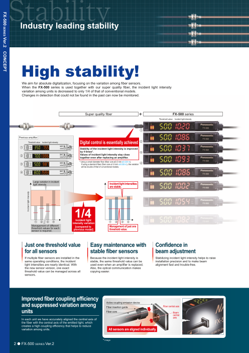
We aim for absolute digitalization, focusing on the variation among fiber sensors.
When the FX-500 series is used together with our super quality fiber, the incident light intensity Introducing the super quality fiber
variation among units is decreased to only 1/4 of that of conventional models.
Changes in detection that could not be found in the past can now be monitored.
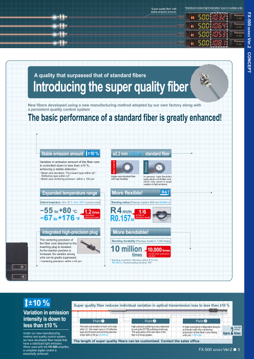
New fibers developed using a new manufacturing method adopted by our own factory along with
a persistent quality control system
Super quality fiber + FX-500 series
Threshold value Incident light intensity The basic performance of a standard fiber is greatly enhanced!
1
Previous amplifier
Threshold value Incident light intensity Digital control is essentially achieved 2
1 Stability of the incident light intensity is improved
by 4 times*. 3 Stable emission amount ±10 % ø2.2 mm ø0.087 in standard fiber
2 Values of incident light intensity stay close
together even after replacing an amplifier. Variation in emission amount of the fiber core
* Using a small diameter fiber (fiber core ø0.5 mm ø0.020 in).
3 If using a standard fiber (fiber core ø1.0 mm ø0.039 in), the variation 4 is controlled down to less than ±10 %,
will be double of that of conventional models. achieving a stable detection.
• Beam axis deviation: Thru-beam type within ±2°,
4 Reflective type within ±3° Single core standard fiber In general, high-flexibility
• Beam axis centering precison: within ± 150 μm with high flexibility types adopt a multi-fiber core,
which may result in large
Large variation in incident variation in light emission.
light intensity. Incident light intensities
are stable.
Expanded temperature range More flexible! R4
Ambient temperature [–40 to +70 °C – 40 to +158 °F in previous model] Bending radius [Previous model is R25 mm R0.984 in]
– +
1/4 55 to 80 °C 1.2 times R4mm 1/6
–67 +176 more than R0.157 of that of
to °F previous model in previous model
1 2 3 4 incident light
intensity variation 1 2 3 4
Management of different
threshold values for each [compared to Management of just one
sensor is required. previous model] threshold value. Integrated high-precision plug More bendable!
The centering precision of Bending durability [Previous model is 1,000 times]
the fiber core attached to the
Just one threshold value Easy maintenance with Confidence in inserting plug is doubled.
As the insertion precision is 10 million 10,000 times
for all sensors stable fiber sensors beam adjustment increased, the variation among times more than previous
units can be greatly suppressed. model
• Centering precision: within ± 40 μm * Bending conditons: Bending radius R10 mm
If multiple fiber sensors are installed in the Because the incident light intensity is Stabilizing incident light intensity helps to raise R0.394 in, Reciprocating bending 180°
same operating conditions, the incident stable, the same threshold value can be installation precision and to make beam
light intensities are nearly identical. With used even when an amplifier is replaced. alignment fast and trouble-free.
the new sensor version, one exact Also, the optical communication makes
threshold value can be managed across all copying easier.
sensors.
Improved fiber coupling efficiency ±10 % Super quality fiber reduces individual variation in optical transmission loss to less than ±10 %
and suppressed variation among Active coupling emission device
Fiber insertion guide Fiber central axis
units Variation in emission
Fiber core Beam
central intensity is down to 1 2 3
In each unit we have accurately aligned the central axis of axis Point Point Point
the fiber with the central axis of the emitted light, which less than ±10 % The beam axis deviation of each unit is kept High precision polishing is accomplished A high-precision integrated plug is more than
within ±2 ° (thru-beam type) or ±3°(reflective by using the PCTM polishing technique. achieved with the centering previous
creates a high coupling efficiency that helps to reduce Under our new manufacturing type) and the beam axis centering precision The specularity of the end face of the precision of the fiber core being
variation among units. All sensors are aligned individually. Approx. 2 times
method and quality control system, is kept within ±150 μm ±5.906 mil. fiber is 5 times greater. ±40 μm 1.575 mil.
we have developed fiber heads that The length of super quality fibers can be customized. Contact the sales office.
have a stabilized light emission.
* Image When used with the FX-500 amplifier,
2 FX-500 SERIES Ver.2 a complete digital control is FX-500 SERIES Ver.2 3
essentially achieved.
Incident light intensity
New material
Previous
FX-500 SERIES Ver.2 CONCEPT
FX-500 SERIES Ver.2 CONCEPT
Page3
“Super quality fiber” with “Stabilized incident light intensities” even in multiple units
stable emission amount
Industry leading stability
High stability! A quality that surpassed that of standard fibers
We aim for absolute digitalization, focusing on the variation among fiber sensors.
When the FX-500 series is used together with our super quality fiber, the incident light intensity Introducing the super quality fiber
variation among units is decreased to only 1/4 of that of conventional models.
Changes in detection that could not be found in the past can now be monitored.
New fibers developed using a new manufacturing method adopted by our own factory along with
a persistent quality control system
Super quality fiber + FX-500 series
Threshold value Incident light intensity The basic performance of a standard fiber is greatly enhanced!
1
Previous amplifier
Threshold value Incident light intensity Digital control is essentially achieved 2
1 Stability of the incident light intensity is improved
by 4 times*. 3 Stable emission amount ±10 % ø2.2 mm ø0.087 in standard fiber
2 Values of incident light intensity stay close
together even after replacing an amplifier. Variation in emission amount of the fiber core
* Using a small diameter fiber (fiber core ø0.5 mm ø0.020 in).
3 If using a standard fiber (fiber core ø1.0 mm ø0.039 in), the variation 4 is controlled down to less than ±10 %,
will be double of that of conventional models. achieving a stable detection.
• Beam axis deviation: Thru-beam type within ±2°,
4 Reflective type within ±3° Single core standard fiber In general, high-flexibility
• Beam axis centering precison: within ± 150 μm with high flexibility types adopt a multi-fiber core,
which may result in large
Large variation in incident variation in light emission.
light intensity. Incident light intensities
are stable.
Expanded temperature range More flexible! R4
Ambient temperature [–40 to +70 °C – 40 to +158 °F in previous model] Bending radius [Previous model is R25 mm R0.984 in]
– +
1/4 55 to 80 °C 1.2 times R4mm 1/6
–67 +176 more than R0.157 of that of
to °F previous model in previous model
1 2 3 4 incident light
intensity variation 1 2 3 4
Management of different
threshold values for each [compared to Management of just one
sensor is required. previous model] threshold value. Integrated high-precision plug More bendable!
The centering precision of Bending durability [Previous model is 1,000 times]
the fiber core attached to the
Just one threshold value Easy maintenance with Confidence in inserting plug is doubled.
As the insertion precision is 10 million 10,000 times
for all sensors stable fiber sensors beam adjustment increased, the variation among times more than previous
units can be greatly suppressed. model
• Centering precision: within ± 40 μm * Bending conditons: Bending radius R10 mm
If multiple fiber sensors are installed in the Because the incident light intensity is Stabilizing incident light intensity helps to raise R0.394 in, Reciprocating bending 180°
same operating conditions, the incident stable, the same threshold value can be installation precision and to make beam
light intensities are nearly identical. With used even when an amplifier is replaced. alignment fast and trouble-free.
the new sensor version, one exact Also, the optical communication makes
threshold value can be managed across all copying easier.
sensors.
Improved fiber coupling efficiency ±10 % Super quality fiber reduces individual variation in optical transmission loss to less than ±10 %
and suppressed variation among Active coupling emission device
Fiber insertion guide Fiber central axis
units Variation in emission
Fiber core Beam
central intensity is down to 1 2 3
In each unit we have accurately aligned the central axis of axis Point Point Point
the fiber with the central axis of the emitted light, which less than ±10 % The beam axis deviation of each unit is kept High precision polishing is accomplished A high-precision integrated plug is more than
within ±2 ° (thru-beam type) or ±3°(reflective by using the PCTM polishing technique. achieved with the centering previous
creates a high coupling efficiency that helps to reduce Under our new manufacturing type) and the beam axis centering precision The specularity of the end face of the precision of the fiber core being
variation among units. All sensors are aligned individually. Approx. 2 times
method and quality control system, is kept within ±150 μm ±5.906 mil. fiber is 5 times greater. ±40 μm 1.575 mil.
we have developed fiber heads that The length of super quality fibers can be customized. Contact the sales office.
have a stabilized light emission.
* Image When used with the FX-500 amplifier,
2 FX-500 SERIES Ver.2 a complete digital control is FX-500 SERIES Ver.2 3
essentially achieved.
Incident light intensity
New material
Previous
FX-500 SERIES Ver.2 CONCEPT
FX-500 SERIES Ver.2 CONCEPT
Page4
Industry leading sensing performance
Sharp detection with suppressed hysteresis
High-speed response & Ultra long range detection So accurate!
The exclusive detection IC combined with the high-intensity beam emitted from the active coupling emission device The FX-500 with its accurate detection catches fractional differences in
provides the capability of offering high-speed response time over a longer sensing range, opening up new possibilities for light intensity, achieving high precision and solving low-hysteresis FR-Z50HW
fiber sensor detection. applications.
H-02 mode
Long range detection of
Max. 25 μs response time small objects with small
FX-500 with its high response time contributes to improve productivity. difference in light intensity
The FX-500 series achieves a long sensing range by its high
intensity beam in addition to suppressed hysteresis. Detection of
minute objects over a long range is now more accurate than before.
Performing minute object detection when using a small diameter fiber is now possible Comparison image The light intensity
with a high response time and longer sensing range. difference caused by
Optimal sensing region one sheet of glass can
H y p e r
HYPR mode incorporated be detected from a
more distant point.
FX-500 in combination with small diameter fibers which can handle
challenging detections, allows long sensing range.
Max. 5.7 times!
Tough
FD-41 longer than the previous model
FX-500 Conventional FX-500
HYPR mode model (H-02)
Previous FD-NFM2 Reflector
FX-301 (LONG mode)
Note: When using FD-NFM2. H-01 mode Comparison image
Optimal sensing region
Highly accurate High light intensity Light saturated region
(saturation) region is reduced, and
detection while avoiding detection is possible
even under high light
Detecting minute objects High-speed mode saturation intensity.
Small diameter fibers can perform detection in long range and A high speed response time of 25 μs, which is 2.6 Even the light is so strong that it causes
with stability even for minute objects. times faster than the previous model, as well as a saturation, the FX-500 series cuts down
long sensing range are both achieved in hysteresis to the utmost limit in order to
high-speed mode. FT-A11 Conventional FX-500
produce the optimal margin for detection. model (H-01)
The active coupling emission device efficiently Conventional FX-300 FX-500 Hysteresis Mode table Low light intensity region
focuses the beam through small diameter fibers Fiber sensor Built-in optical lens Emitting element in a device Three hysteresis modes Hysteresis Light Optimal sensing region
Mode amount intensity Description
OFF Point ON Point High light intensity (saturation) region
Without lens Double coupling lens Active coupling emission device Hysteresis is the difference in incident Sharp detection with high
The super fine optical lens and emitting element are combined Superfine optical lens light intensity at the points when the ON H-01 Minimal Small accuracy is possible in this mode. H-02 addresses long
Optimal for minute object detection sensing range and low
into one device enabling the beam emitted from the emitting where light saturates easily.
output turns ON and when the output light intensity region.
Initial setting mode.
element to be focused directly into the fiber. turns OFF. Hysteresis was originally Ex. Detecting large glass substrate
H-02 Small Large Accurate detection such as
Coupling efficiency is therefore increased by 50 % compared intended to be used as a measure OFF long range detection of a large
glass substrate is possible.
to standard fiber (core ø1 mm ø0.039 in). In particular, the High luminance
Four-chemical four-chemical against vibrations. Three hysteresis A mode used for prevention of H-01 addresses short
small diameter fibers (core ø0.5 mm ø0.020 in) see a dramatic Emitting element emitting element emitting element modes are available to support the H-03 Large Large chattering. sensing range and
Works in adverse environments high light intensity region.
increase in light intensity, making challenging detections Coupling efficiency more than 50 % wide variety of applications for which
Coupling efficiency approx. 10 % Coupling efficiency approx. 20 % Small Incident light intensity Large such as vibration or dirt. Conventional H-01 H-02
possible. fiber sensors are optimally suited. model FX-500 Ex. Detecting wire
Coupling efficiency = (light intensity directed into the fiber / emission intensity of active coupling emission device) × 100 * Image
4 FX-500 SERIES Ver.2 FX-500 SERIES Ver.2 5
Short Sensing range Long
Short Sensing range Long
Short Sensing renge Long
FX-500 SERIES Ver.2 CONCEPT
FX-500 SERIES Ver.2 CONCEPT
Page5
Industry leading sensing performance
Sharp detection with suppressed hysteresis
High-speed response & Ultra long range detection So accurate!
The exclusive detection IC combined with the high-intensity beam emitted from the active coupling emission device The FX-500 with its accurate detection catches fractional differences in
provides the capability of offering high-speed response time over a longer sensing range, opening up new possibilities for light intensity, achieving high precision and solving low-hysteresis FR-Z50HW
fiber sensor detection. applications.
H-02 mode
Long range detection of
Max. 25 μs response time small objects with small
FX-500 with its high response time contributes to improve productivity. difference in light intensity
The FX-500 series achieves a long sensing range by its high
intensity beam in addition to suppressed hysteresis. Detection of
minute objects over a long range is now more accurate than before.
Performing minute object detection when using a small diameter fiber is now possible Comparison image The light intensity
with a high response time and longer sensing range. difference caused by
Optimal sensing region one sheet of glass can
H y p e r
HYPR mode incorporated be detected from a
more distant point.
FX-500 in combination with small diameter fibers which can handle
challenging detections, allows long sensing range.
Max. 5.7 times!
Tough
FD-41 longer than the previous model
FX-500 Conventional FX-500
HYPR mode model (H-02)
Previous FD-NFM2 Reflector
FX-301 (LONG mode)
Note: When using FD-NFM2. H-01 mode Comparison image
Optimal sensing region
Highly accurate High light intensity Light saturated region
(saturation) region is reduced, and
detection while avoiding detection is possible
even under high light
Detecting minute objects High-speed mode saturation intensity.
Small diameter fibers can perform detection in long range and A high speed response time of 25 μs, which is 2.6 Even the light is so strong that it causes
with stability even for minute objects. times faster than the previous model, as well as a saturation, the FX-500 series cuts down
long sensing range are both achieved in hysteresis to the utmost limit in order to
high-speed mode. FT-A11 Conventional FX-500
produce the optimal margin for detection. model (H-01)
The active coupling emission device efficiently Conventional FX-300 FX-500 Hysteresis Mode table Low light intensity region
focuses the beam through small diameter fibers Fiber sensor Built-in optical lens Emitting element in a device Three hysteresis modes Hysteresis Light Optimal sensing region
Mode amount intensity Description
OFF Point ON Point High light intensity (saturation) region
Without lens Double coupling lens Active coupling emission device Hysteresis is the difference in incident Sharp detection with high
The super fine optical lens and emitting element are combined Superfine optical lens light intensity at the points when the ON H-01 Minimal Small accuracy is possible in this mode. H-02 addresses long
Optimal for minute object detection sensing range and low
into one device enabling the beam emitted from the emitting where light saturates easily.
output turns ON and when the output light intensity region.
Initial setting mode.
element to be focused directly into the fiber. turns OFF. Hysteresis was originally Ex. Detecting large glass substrate
H-02 Small Large Accurate detection such as
Coupling efficiency is therefore increased by 50 % compared intended to be used as a measure OFF long range detection of a large
glass substrate is possible.
to standard fiber (core ø1 mm ø0.039 in). In particular, the High luminance
Four-chemical four-chemical against vibrations. Three hysteresis A mode used for prevention of H-01 addresses short
small diameter fibers (core ø0.5 mm ø0.020 in) see a dramatic Emitting element emitting element emitting element modes are available to support the H-03 Large Large chattering. sensing range and
Works in adverse environments high light intensity region.
increase in light intensity, making challenging detections Coupling efficiency more than 50 % wide variety of applications for which
Coupling efficiency approx. 10 % Coupling efficiency approx. 20 % Small Incident light intensity Large such as vibration or dirt. Conventional H-01 H-02
possible. fiber sensors are optimally suited. model FX-500 Ex. Detecting wire
Coupling efficiency = (light intensity directed into the fiber / emission intensity of active coupling emission device) × 100 * Image
4 FX-500 SERIES Ver.2 FX-500 SERIES Ver.2 5
Short Sensing range Long
Short Sensing range Long
Short Sensing renge Long
FX-500 SERIES Ver.2 CONCEPT
FX-500 SERIES Ver.2 CONCEPT
Page6
Class leading form and operability A variety of functions at the industry’s leading edge
Stable detection while being eco-friendly
New form! Previous s Emission power & gain setting
pace re In cases when the incident light intensity Detecting a transparent sheet
is saturated, the light emitting amount can
be adjusted to the optimal level by AUTO Normal AUTO
Flat display with wide viewing angle without changing the response time. This
allows stable detection with an optimal
Object present
The large and high-contrast 7-segment display of high luminance provides clear visibility Compact cover does not get in the way S/N ratio and saves energy by controlling
from a wide angle of view. the emitting electric current.
Reduced to 1/3 of the previous model’s size Object absent
Auto mode (AUTO) and 3-level manual mode Saturated
Clearly visible even (H / M / L [fine-adjustable]) are incorporated.
from sideways
Built-in logic functions
R23 No PLC necessary. Logical calculation with fiber sensor only
mm
R0.906 in Logical calculation functions
Three logical calculations (AND, OR, XOR) Calculation of two neighboring amplifiers Truth table
are available with fiber sensor only.
Lower side Output 1: Normal output operation
3 logical operation can be selected against Calculation result Logical calculation output (C)
Output 1. Additional controller is not Lower side Output 1 output
required so both wire-saving and cost Upper side Output 1 Normal output
operation
reduction can be achieved. Communication direction (Up to 12 units)
Calculation of two outputs in one amplifier FX-502(P) / FX-505(P)-C2
Output 1: Normal output operation
Detection fiber
Output 1 Calculation result output
Output 2 Normal output operation
Streamlined fiber clamp MODE NAVI + Direct setting Calculation of one amplifier and external input FX-502(P) / FX-505(P)-C2
Output 1: Normal output operation
Conventionally clamp operation was performed after opening up the MODE NAVI uses three indicators and a dual display to show the
cover. The FX-500 series adopts a guard structure eliminating the amplifier’s basic operations. The current operation mode can be External input
cover so that the clamp operation can be done in one step. confirmed at a glance, so even a first-time user can easily operate the (sensor, contact, PLC, etc.)
amplifier. Synchronization fiber Output 1 Calculation result output
Saves maintenance time
Streamlined fiber clamp NAVI display (lights off during RUN mode) Threshold tracking function
Conventional Selectable interference prevention
L/D
Switches output operation. This function performs automatic setting of threshold value by checking the In addition to the automatic interference prevention function which is enabled
L: Light-ON D: Dark-ON
incident light intensity at desired intervals in order to follow the changes in through the optical communication of amplifiers mounted in cascade, an
Fiber lock lever CUST the light amount resulting from changes in the environment over long alternate frequency interference prevention function is also incorporated. So
Allows direct setting change selectable from response periods (such as dust). This contributes to reduction in maintenance hours. even for layouts where optical communication cannot be carried out,
time / hysteresis / emitting power / emission. switching of emission frequencies allows interference prevention.
(Initial setting: response time) SHIFT AUTO
PRO (Tracking by limit teaching) (Tracking by automatic teaching) Automatic interference prevention Alternate frequency interference prevention
Fiber installation takes one step due to the eliminated cover. (When amplifiers are mounted in cascade) (When amplifiers are not mounted in cascade)
Large cover model takes 3 steps. Allows the selection of advanced functions Effective for thru-beam type
such as timer, copy, and memory functions. Effective for reflective type!
and retroreflective type! (Dark-ON) Emission frequency 1
Conventional Optical communication Emission frequency 2
Guard structure Direct setting Large Large
ON Threshold
value Emission frequency 3
Direct adjustment Direct teaching Current Current
value value
Press once * Refer to specifications for details of number of sensors allowed in interference prevention.
Threshold OFF
each for object
“present” and Small value Small
The guard structure
incorporated prevents “absent” Time Time
the lever from
disengaging due to The lever is exposed and may Limit teaching is performed Automatic teaching which
accidental impact. be accidentally disengaged. periodically. triggers output is performed.
Threshold value can be changed during RUN mode. Teaching can be done during RUN mode.
6 FX-500 SERIES Ver.2 FX-500 SERIES Ver.2 7
Incident light
intensity
Incident light
intensity
FX-500 SERIES Ver.2 CONCEPT
entm
uir
e
q
FX-500 SERIES Ver.2 CONCEPT
Page7
Class leading form and operability A variety of functions at the industry’s leading edge
Stable detection while being eco-friendly
New form! Previous s Emission power & gain setting
pace re In cases when the incident light intensity Detecting a transparent sheet
is saturated, the light emitting amount can
be adjusted to the optimal level by AUTO Normal AUTO
Flat display with wide viewing angle without changing the response time. This
allows stable detection with an optimal
Object present
The large and high-contrast 7-segment display of high luminance provides clear visibility Compact cover does not get in the way S/N ratio and saves energy by controlling
from a wide angle of view. the emitting electric current.
Reduced to 1/3 of the previous model’s size Object absent
Auto mode (AUTO) and 3-level manual mode Saturated
Clearly visible even (H / M / L [fine-adjustable]) are incorporated.
from sideways
Built-in logic functions
R23 No PLC necessary. Logical calculation with fiber sensor only
mm
R0.906 in Logical calculation functions
Three logical calculations (AND, OR, XOR) Calculation of two neighboring amplifiers Truth table
are available with fiber sensor only.
Lower side Output 1: Normal output operation
3 logical operation can be selected against Calculation result Logical calculation output (C)
Output 1. Additional controller is not Lower side Output 1 output
required so both wire-saving and cost Upper side Output 1 Normal output
operation
reduction can be achieved. Communication direction (Up to 12 units)
Calculation of two outputs in one amplifier FX-502(P) / FX-505(P)-C2
Output 1: Normal output operation
Detection fiber
Output 1 Calculation result output
Output 2 Normal output operation
Streamlined fiber clamp MODE NAVI + Direct setting Calculation of one amplifier and external input FX-502(P) / FX-505(P)-C2
Output 1: Normal output operation
Conventionally clamp operation was performed after opening up the MODE NAVI uses three indicators and a dual display to show the
cover. The FX-500 series adopts a guard structure eliminating the amplifier’s basic operations. The current operation mode can be External input
cover so that the clamp operation can be done in one step. confirmed at a glance, so even a first-time user can easily operate the (sensor, contact, PLC, etc.)
amplifier. Synchronization fiber Output 1 Calculation result output
Saves maintenance time
Streamlined fiber clamp NAVI display (lights off during RUN mode) Threshold tracking function
Conventional Selectable interference prevention
L/D
Switches output operation. This function performs automatic setting of threshold value by checking the In addition to the automatic interference prevention function which is enabled
L: Light-ON D: Dark-ON
incident light intensity at desired intervals in order to follow the changes in through the optical communication of amplifiers mounted in cascade, an
Fiber lock lever CUST the light amount resulting from changes in the environment over long alternate frequency interference prevention function is also incorporated. So
Allows direct setting change selectable from response periods (such as dust). This contributes to reduction in maintenance hours. even for layouts where optical communication cannot be carried out,
time / hysteresis / emitting power / emission. switching of emission frequencies allows interference prevention.
(Initial setting: response time) SHIFT AUTO
PRO (Tracking by limit teaching) (Tracking by automatic teaching) Automatic interference prevention Alternate frequency interference prevention
Fiber installation takes one step due to the eliminated cover. (When amplifiers are mounted in cascade) (When amplifiers are not mounted in cascade)
Large cover model takes 3 steps. Allows the selection of advanced functions Effective for thru-beam type
such as timer, copy, and memory functions. Effective for reflective type!
and retroreflective type! (Dark-ON) Emission frequency 1
Conventional Optical communication Emission frequency 2
Guard structure Direct setting Large Large
ON Threshold
value Emission frequency 3
Direct adjustment Direct teaching Current Current
value value
Press once * Refer to specifications for details of number of sensors allowed in interference prevention.
Threshold OFF
each for object
“present” and Small value Small
The guard structure
incorporated prevents “absent” Time Time
the lever from
disengaging due to The lever is exposed and may Limit teaching is performed Automatic teaching which
accidental impact. be accidentally disengaged. periodically. triggers output is performed.
Threshold value can be changed during RUN mode. Teaching can be done during RUN mode.
6 FX-500 SERIES Ver.2 FX-500 SERIES Ver.2 7
Incident light
intensity
Incident light
intensity
FX-500 SERIES Ver.2 CONCEPT
entm
uir
e
q
FX-500 SERIES Ver.2 CONCEPT
Page8
A variety of functions at the industry’s leading edge
Resolves variation in displayed incident light intensity
Display adjustment setting Display Equipped with 5 timer types An optical communication function allows
adjustment
setting
A wide variety of timer control operations can be carried out by fiber sensors to be adjusted simultaneously
The variation in display can be adjusted to random values. This helps to sensors only.
define proper instruction in a work order. The data that is currently set can be copied and saved all at once for all
Time chart Set to L-ON amplifiers connected togther from the right side thanks to the optical
Beam-
Sensing received communication function.
condition Beam-
interrupted This greatly reduces troublesome setup tasks and makes setup much
Variation in incident light intensity Unify incident light intensity into any value ON
ON-delay T1
OFF smoother.
ON
OFF-delay T1 T1 OFF
Stable detection over long and short periods Stable sensing comparison ON
One-shot T1 T1 OFF Single copy & save operation
Stabilized emission amount Four-chemical emitting element + APC ON OFF- T T ON for all amplifiers
1 2
Short-term stability (FX-500) delay OFF * Timer period: 0.05 ms to 32 s
* Output 1 has ON / OFF-delay and
Three-chemical emitting element ON-delay / T T ON
1 2 ON-delay / One-shot timers are
The “four-chemical emitting element”, which we were the first to incorporate (without APC) One-shot OFF available for Output 1 only. Optical communication
to maintain a stable level of light emission, has now become an industry window
Deviation
standard.
FX-500 series continues to adopt the same emitting element as well as the Long-term stability No need to specify a main unit or sub unit Wire-saving, space-saving
“APC (Auto Power Control) circuit” which improves stability in short periods
such as when the power is turned on. All FX-500 amplifiers can be used as either a main unit or a sub unit. Just The quick-connection cables enable reduction in wiring. The connections
use a main cable or a sub cable to distinguish the two. This reduces the and man-hours required for the relay terminal block setup can be reduced
costs of inventory management. and valuable space is saved.
Time
Suitable for preventative maintenance The same part number
Large can be used as either
Self-diagnosis output Change in light intensity Teaching again
FX-502(P) / FX-505(P)-C2 (preventative maintenance) a main unit or sub unit! Up to 16 sensors allowed in power-supply wire-saving
Output 2
FX-502(P) / FX-505(P)-C2 Detect deterioration in light intensity threshold
value Auto set
can set Output 2 as a (e.g. Useful in dusty environment) to 50%
self-diagnosis output. When Sub cable
the teaching of Output 1’s Output 1 Auto set
threshold value is carried out, threshold value to 50% again
Output 2 is set concurrently Main cable (3-core)
with the setting randomly Self-diagnosis output (alarm) - -
FX-501□ CN 73 C□
Sub cable (1-core)
shifted by the amount of CN-71-C□
surplus of threshold value. - -
Small Main cable (4-core) CN 71/72 C□
- -
Light intensity deterioration CN 74 C□
FX-502□ Main cable Disconnection is possible without
due to fiber breakage or Self-diagnosis can be used with the threshold tracking Sub cable (2-core)
Time moving the amplifier sideways CN-73/74-C□ * Connection of up to 16 units with FX-400 / DPS-400 / LS-400 is possible.
CN-72-C□
function for added effectiveness. * Up to 12 sensors in optical communication.
dust accumulation can be
notified as an alarm output. Network communication
8 data banks
Connection to CC-Link IE Field / CC-Link / DeviceNet / EtherCAT open network is possible through the communication unit for open network, SC-GU3 series.
Analog output cable type FX-505(P)-C2 Smooth setup changes Monitoring or setting changes can be carried out via a PLC, PC, etc.
CC-Link IE Field and CC-Link are trademarks of Mitsubishi Electric Corporation,
To monitor the sensing of objects, a 4 to 20 mA analog current is output The number of data banks used for saving the setup conditions of the amplifier and are controlled by the CC-Link Partner Association.
in respond to the digital value of the incident light intensity. is increased to eight. Setup conditions can be saved and loaded to make DeviceNet is a registered trademark of Open DeviceNet Vendor
Association (ODVA), Inc.
setup changes easy at a worksite where multiple models are manufactured. EtherCAT is a registered trademark of Beckhoff Automation GmbH.
Edge tracking of film or sheet
20 External input
Actual position
Drift position Remote control improves work efficiency FX-502(P) / Current values Communication Unit
FX-505(P)-C2
of connected for Open Network
sensors are shown. SC-GU3 series
Work efficiency can be improved by operating via PLC output or other Digital fiber sensor FX-501/502
external signal. Digital fiber sensor FX-301/305
4 (FX-502(P) can operate via external signal when switching from Output 2 to しきい値 現在値 しきい値 現在値 Digital laser sensor LS-501/403
1ch 90 65 9ch 0 0
2ch 50 0 10ch 0 0 Digital pressure sensor DPS-401/402
0 Incident light intensity (digit) 4,000/8,000 external input.) 3ch 40 70 11ch 0 0
4ch 0 0 12ch 0 0
5ch 0 0 13ch 0 0
Functions operable by external input End unit
6ch 0 0 14ch 0 0
7ch 0 0 15ch 0 0
8ch 0 0 16ch 0 0
Full-auto* / Limit* / 2-point teaching* Display adjustment setting*
The drifting path can be monitored [Touch panel display example]
Data bank load* / save* Logical calculation (self-unit only)
as the light intensity changes. Threshold values of Please refer to our website for details of SC-GU3 series.
Emission halt Copying function lock (self-unit only) connected sensors
* FX-505(P)-C2 conducts the answer back output toward external input, when setting Sensing output are shown.
2 to the anser back output mode.
8 FX-500 SERIES Ver.2 FX-500 SERIES Ver.2 9
Output current (mA)
Light emiting amount
Incident light intensity
Power supply
cable
Output line 1
Output line 2
Output line 16
FX-500 SERIES Ver.2 CONCEPT
FX-500 SERIES Ver.2 CONCEPT
Page9
A variety of functions at the industry’s leading edge
Resolves variation in displayed incident light intensity
Display adjustment setting Display Equipped with 5 timer types An optical communication function allows
adjustment
setting
A wide variety of timer control operations can be carried out by fiber sensors to be adjusted simultaneously
The variation in display can be adjusted to random values. This helps to sensors only.
define proper instruction in a work order. The data that is currently set can be copied and saved all at once for all
Time chart Set to L-ON amplifiers connected togther from the right side thanks to the optical
Beam-
Sensing received communication function.
condition Beam-
interrupted This greatly reduces troublesome setup tasks and makes setup much
Variation in incident light intensity Unify incident light intensity into any value ON
ON-delay T1
OFF smoother.
ON
OFF-delay T1 T1 OFF
Stable detection over long and short periods Stable sensing comparison ON
One-shot T1 T1 OFF Single copy & save operation
Stabilized emission amount Four-chemical emitting element + APC ON OFF- T T ON for all amplifiers
1 2
Short-term stability (FX-500) delay OFF * Timer period: 0.05 ms to 32 s
* Output 1 has ON / OFF-delay and
Three-chemical emitting element ON-delay / T T ON
1 2 ON-delay / One-shot timers are
The “four-chemical emitting element”, which we were the first to incorporate (without APC) One-shot OFF available for Output 1 only. Optical communication
to maintain a stable level of light emission, has now become an industry window
Deviation
standard.
FX-500 series continues to adopt the same emitting element as well as the Long-term stability No need to specify a main unit or sub unit Wire-saving, space-saving
“APC (Auto Power Control) circuit” which improves stability in short periods
such as when the power is turned on. All FX-500 amplifiers can be used as either a main unit or a sub unit. Just The quick-connection cables enable reduction in wiring. The connections
use a main cable or a sub cable to distinguish the two. This reduces the and man-hours required for the relay terminal block setup can be reduced
costs of inventory management. and valuable space is saved.
Time
Suitable for preventative maintenance The same part number
Large can be used as either
Self-diagnosis output Change in light intensity Teaching again
FX-502(P) / FX-505(P)-C2 (preventative maintenance) a main unit or sub unit! Up to 16 sensors allowed in power-supply wire-saving
Output 2
FX-502(P) / FX-505(P)-C2 Detect deterioration in light intensity threshold
value Auto set
can set Output 2 as a (e.g. Useful in dusty environment) to 50%
self-diagnosis output. When Sub cable
the teaching of Output 1’s Output 1 Auto set
threshold value is carried out, threshold value to 50% again
Output 2 is set concurrently Main cable (3-core)
with the setting randomly Self-diagnosis output (alarm) - -
FX-501□ CN 73 C□
Sub cable (1-core)
shifted by the amount of CN-71-C□
surplus of threshold value. - -
Small Main cable (4-core) CN 71/72 C□
- -
Light intensity deterioration CN 74 C□
FX-502□ Main cable Disconnection is possible without
due to fiber breakage or Self-diagnosis can be used with the threshold tracking Sub cable (2-core)
Time moving the amplifier sideways CN-73/74-C□ * Connection of up to 16 units with FX-400 / DPS-400 / LS-400 is possible.
CN-72-C□
function for added effectiveness. * Up to 12 sensors in optical communication.
dust accumulation can be
notified as an alarm output. Network communication
8 data banks
Connection to CC-Link IE Field / CC-Link / DeviceNet / EtherCAT open network is possible through the communication unit for open network, SC-GU3 series.
Analog output cable type FX-505(P)-C2 Smooth setup changes Monitoring or setting changes can be carried out via a PLC, PC, etc.
CC-Link IE Field and CC-Link are trademarks of Mitsubishi Electric Corporation,
To monitor the sensing of objects, a 4 to 20 mA analog current is output The number of data banks used for saving the setup conditions of the amplifier and are controlled by the CC-Link Partner Association.
in respond to the digital value of the incident light intensity. is increased to eight. Setup conditions can be saved and loaded to make DeviceNet is a registered trademark of Open DeviceNet Vendor
Association (ODVA), Inc.
setup changes easy at a worksite where multiple models are manufactured. EtherCAT is a registered trademark of Beckhoff Automation GmbH.
Edge tracking of film or sheet
20 External input
Actual position
Drift position Remote control improves work efficiency FX-502(P) / Current values Communication Unit
FX-505(P)-C2
of connected for Open Network
sensors are shown. SC-GU3 series
Work efficiency can be improved by operating via PLC output or other Digital fiber sensor FX-501/502
external signal. Digital fiber sensor FX-301/305
4 (FX-502(P) can operate via external signal when switching from Output 2 to しきい値 現在値 しきい値 現在値 Digital laser sensor LS-501/403
1ch 90 65 9ch 0 0
2ch 50 0 10ch 0 0 Digital pressure sensor DPS-401/402
0 Incident light intensity (digit) 4,000/8,000 external input.) 3ch 40 70 11ch 0 0
4ch 0 0 12ch 0 0
5ch 0 0 13ch 0 0
Functions operable by external input End unit
6ch 0 0 14ch 0 0
7ch 0 0 15ch 0 0
8ch 0 0 16ch 0 0
Full-auto* / Limit* / 2-point teaching* Display adjustment setting*
The drifting path can be monitored [Touch panel display example]
Data bank load* / save* Logical calculation (self-unit only)
as the light intensity changes. Threshold values of Please refer to our website for details of SC-GU3 series.
Emission halt Copying function lock (self-unit only) connected sensors
* FX-505(P)-C2 conducts the answer back output toward external input, when setting Sensing output are shown.
2 to the anser back output mode.
8 FX-500 SERIES Ver.2 FX-500 SERIES Ver.2 9
Output current (mA)
Light emiting amount
Incident light intensity
Power supply
cable
Output line 1
Output line 2
Output line 16
FX-500 SERIES Ver.2 CONCEPT
FX-500 SERIES Ver.2 CONCEPT
Page10
1.6 times longer sensing range than conventional models
Significantly improved stability and usability
Sensing
range
1.6 times Entry
longer than model
conventional
models
Sensing range up to 1.6 times
Ample sensing distance even with thin fiber
The sensing range of the thin reflective type fiber is about 1.6 times longer than that of a conventional product (the sensing range of the standard reflective type
fiber is about 1.4 times longer). This adds extra flexibility to the sensor layout.
Sensing range (STD mode)
Fiber Rate of increase
FX-551 FX-501 in sensing range FX-551 FD-41
STD mode
FT-31 480 mm 18.898 in 315 mm 12.402 in 152 % 1.6 times approx.
FT-42 1,470 mm 57.874 in 1,130 mm 44.488 in 130 % FX-501 FD-41 longer than conventional models!
FD-41 200 mm 7.874 in 125 mm 4.921 in 160 % STD mode
FD-61 620 mm 24.409 in 450 mm 17.717 in 138 %
When the hysteresis is the same, the higher incident
light intensity results in more stable detection. Easy adjustment of beam axis
When the hysteresis is the same, the higher Thanks to the high emission power,
incident light intensity results in more stable a slight deviation of beam axis
detection. causes no problem.
It is ideal for use in dusty areas* or
for detection through an extremely
small slit.
FX-551
Stable detection!
FX-501 * Need to confirm proper operation in
installed condition.
Distance
Equipped with a mode to minimize the effect
of ambient light
When setting to activate the
environment resistance mode in the
emission frequency setting, the
ambient illuminance for LED lights
becomes about 2.5 times higher than
that in the normal mode. This reduces
erroneous detections caused by LED
lights.
10 FX-550 SERIES FX-550 SERIES 11
Incident light intensity
FX-550 SERIES FUNCTION
FX-550 SERIES CONCEPT
Page11
1.6 times longer sensing range than conventional models
Significantly improved stability and usability
Simplified functions for improved operation ease
The FX-500 series and newer models are equipped with only basic functions for improved ease of use. No matter which model you select, they are all easy
to use.
MODE NAVI + Direct setting
MODE NAVI uses three indicators and a dual display to show the amplifier’s basic operations. The current operation mode can be confirmed at a glance,
so even a first-time user can easily operate the amplifier.
NAVI display (lights off during RUN mode) Direct setting
L/D Direct adjustment Direct teaching
Sensing Switches output operation.
L: Light-ON D: Dark-ON Press once
range each for object
1.6 times Entry CUST “present” and
The sensitivity to received light can be “absent”
changed directly.
longer than model PRO Threshold value can be changed Teaching can be done during
conventional Allows the selection of advanced functions during RUN mode. RUN mode.
models such as timer, shift amount setting and
threshold value tracking setting.
List of functions in PRO mode
PRO 1 Response time setting, timer setting, shift amount setting
PRO 2 Teaching lock setting, digital display item setting, digital display turning setting, Eco setting
PRO 3 Display adjustment setting, reset setting, emission frequency setting, threshold value tracking setting
No need to specify a main unit or sub unit Wire-saving, space-saving
All FX-500 amplifiers can be used as either a main unit or a sub unit. The quick-connection cables enable reduction in wiring. The connections
Just use a main cable or a sub cable to distinguish the two. This reduces and man-hours required for the relay terminal block setup can be reduced
the costs of inventory management. and valuable space is saved.
The same part number
can be used as either
a main unit or sub unit! Up to 16 sensors allowed in power-supply wire-saving
Sub cable
Main cable Disconnection is CN-71-C□
possible without
moving the CN-73-C□ * Connection of up to 16 units with
amplifier sideways FX-500 / FX-400 / DPS-400 / LS-400 is possible.
Note: FX-550 series is not equipped with a communication function.
When connecting to the host communication units SC-GU3
series, SC-GU2-C and SC-GU1-485, please use FX-500 series.
10 FX-550 SERIES FX-550 SERIES 11
Power supply
cable
Output line 1
Output line 2
Output line 16
FX-550 SERIES FUNCTION
FX-550 SERIES CONCEPT
Page12
Reduction of the data analysis burden - one small step towards IoT.
IO-Link Compatible, Self-Monitoring Type Self-Monitoring Sensor
IO-Link compatible Collecting sensor level data
Field data collected and accumulated for “preventive maintenance” and “operation monitoring”.
An analysis of such field data requires high-level know-how and time, causing a burden to people responsible for the
production site management.
The Self-Monitoring Sensor manufactured by Panasonic is capable of reporting sensor data and its own state to the host
device through the I/O Link master.
With the Self-Monitoring Sensor, you can immediately judge the state of the sensor and easily identify the cause of failure.
Thus, this sensor contributes to the reduction of the burden experienced by the client in collecting and analyzing data.
What is “IO-Link”?
For edges PC
IO-Link is an open communication technology Controller level
according to IEC 61131-9 for the 1:1 bidirectional
communication between the IO-Link device (sensor For collecting PLC
or actuator) and the IO-Link master. data
PLC PLC
Field level
Industrial network
IO-Link master
Sensor level
Normal Caution Fault State information
Incident light Pressure Distance Incident light
intensity value measurement value intensity
information, etc.
IO-Link Compatible, Dual Display Digital CMOS type
Self-Monitoring type Pressure Sensor Micro Laser Distance Sensor
FX-550L SERIES DP-100L SERIES HG-C1000L SERIES
With the Panasonic’s Self-Monitoring Sensor, you can leave the sensor to diagnose its own state!
Examples of IoT in the industrial automation field
Before the introduction of Self-Monitoring Sensors After the introduction of
Self-Monitoring Sensors
Preventive ●W e want to avoid production line stoppage that might occur due to
unexpected sensor failure.
maintenance Line stoppage hours × (manufacturing unit cost / hour) = Loss From preventive maintenance
●We want to minimize the production line down time to almost zero. to predictive maintenance
Leave the sensor diagnosis to the
sensor itself.
● All you need to do is to monitor the sensor
state.
● PLC can be used exclusively for controlling
devices.
● Possible to check detail information at a
desired timing.
Leave the resetting for replaced
sensors to the higher-level master
Problems ● A utomatically written from the connected
master.
The amount of data to be collected is large and this may lower the PLC processing capacity. ● P ossible not only to save time but also to
The burden of data analysis is large. Resetting the replaced sensors is troublesome. prevent human errors.
12 FX-550L SERIES FX-550L SERIES 13
FX-550L SERIES FUNCTION
FX-550L SERIES FUNCTION
Page13
Self-monitoring function
With the Panasonic’s Self-Monitoring Sensor,
you can get high-level solutions!
The introduction of IoT requires collection of the incident light intensity data and presents the following problems.
Incident light intensity
Sensor
PLC Previously only ON/OFF data was
Sensor
required. But, due to an addition of the
Sensor incident light intensity data, the PLC
processing burden has increased.
Sensor
● I ncident light intensity
change graph Noticed a change in the We noticed a change in the incident light
incident light intensity!
intensity. However, because there is no
Incident
light Normal to what judgment criteria, we cannot tell whether
intensity level?
Fault from what the incident light status is normal or not.
level?
Time
Causes Countermeasures
Unless we identify the cause of changes
Stained? Service
life? Cleaning? Replacement? in the incident light intensity, we cannot
optimize countermeasures targeting the
Broken? Short- Wiring
circuited? checking? sensors.
Problems are solved by the high-level self-diagnosis.
Status Judgement of the state
Normal Operation is normal.
Check the settings. * R ecover to the normal state through
Notification Detected state is faulty. checking installation and settings.
Reduction in the incident light intensity
Getting close to the end of service life.
Caution Reached the state where the device * L imitation in the writing frequency into the
should be replaced. memory or in the operation hours, etc.
Short-circuited or broken.
Fault Reached the state where it is impossible to * Short-circuited output, damaged EEPROM,
control as a device. etc.
* By creating a program with a PLC, etc., the "State" of the self-monitoring sensor can be grasped.
Easy use of IoT
Monitoring distance
measurement value “Predictive maintenance” can be easily
Burden Analyzing and
making judgment
imposed Identifying the achieved through monitoring the state
on users cause of the Self-Monitoring Sensor.
Taking Monitoring
countermeasures the state
12 FX-550L SERIES FX-550L SERIES 13
Reduction of
the burden
FX-550L SERIES FUNCTION
FX-550L SERIES FUNCTION
Page14
FX-500/FX-550/FX-550L
ORDER GUIDE
Amplifiers Quick-connection cable is not supplied with the amplifier. Please order it separately.
Type Appearance Model No. Emitting
element Output External input
FX-501 NPN open-collector transistor
–
FX-501P PNP open-collector transistor
FX-502 NPN open-collector transistor
2 outputs
FX-500 Incorporated
series Red LED (Switchable with Output 2)
FX-502P PNP open-collector transistor
2 outputs
FX-505-C2 NPN open-collector transistor
2 outputs, analog output
Incorporated
FX-505P-C2 PNP open-collector transistor
2 outputs, analog output
FX-551 NPN open-collector transistor
FX-551P PNP open-collector transistor
FX-550 Red LED –
series
FX-551-C2 NPN open-collector transistor
FX-551P-C2 PNP open-collector transistor
FX-551L3-P-C2
FX-550L
series
( I O- Lin k ) Red LED PNP open-collector transistor –
compatible
FX-551L3-P-J
Supports (Note)
Note: Smartclick is a trademark of OMRON Corporation.
14
M12 connector type Discrete wire type Cable type Connector type Cable type 2-output type Standard type
Page15
FX-500/FX-550/FX-550L
ORDER GUIDE
Quick-connection cables
For FX-501(P) / FX-551(P) Quick-connection cable is not supplied with the amplifier. Please order it separately.
Main cable
Type Model No. Description • CN-73-C□
CN-73-C1 Length: 1 m 3.281 ft
Main cable 0.2 mm2 3-core cabtyre cable, with connector
(3-core) CN-73-C2 Length: 2 m 6.562 ft on one end
Cable outer diameter: ø3.3 mm ø0.130 in
CN-73-C5 Length: 5 m 16.404 ft Sub cable
CN-71-C1 Length: 1 m 3.281 ft 0.2 mm2 1-core cabtyre cable, with connector • CN-71-C□
Sub cable
(1-core) CN-71-C2 Length: 2 m 6.562 ft on one end
Cable outer diameter: ø3.3 mm ø0.130 in
CN-71-C5 Length: 5 m 16.404 ft Connectable to a main cable up to 15 cables.
For FX-502(P) Quick-connection cable is not supplied with the amplifier. Please order it separately.
Main cable
Type Model No. Description • CN-74-C□
CN-74-C1 Length: 1 m 3.281 ft
Main cable 0.2 mm2 4-core cabtyre cable, with connector
(4-core) CN-74-C2 Length: 2 m 6.562 ft on one end
Cable outer diameter: ø3.3 mm ø0.130 in
CN-74-C5 Length: 5 m 16.404 ft Sub cable
CN-72-C1 Length: 1 m 3.281 ft 0.2 mm2 2-core cabtyre cable, with connector • CN-72-C□
Sub cable on one end
(2-core) CN-72-C2 Length: 2 m 6.562 ft Cable outer diameter: ø3.3 mm ø0.130 in
CN-72-C5 Length: 5 m 16.404 ft Connectable to a main cable up to 15 cables.
End plates End plates are not supplied with the amplifier. Please order them separately when the amplifiers are mounted in cascade.
Appearance Model No. Description
When amplifiers are mounted in cascade, or when an
amplifier moves depending on the way it is installed
on a DIN rail, these end plates clamp amplifiers into
MS-DIN-E place on both sides. Make sure to use end plates
when cascading multiple amplifiers together.
Two pcs. per set
OPTIONS
Amplifier mounting bracket
Designation Model No. Description • MS-DIN-2
Amplifier mounting bracket MS-DIN-2 Mounting bracket for amplifier
Amplifier protection seal
• FX-MB1
10 sets of 2 communication Communication
window seal
window seals and 1 connector
seal
Connector seal
Recommended extension cables for M12 connector type
Manufactured by OMRON Corporation
Extension cable with connectors on both ends XS5W series
* Smartclick is a trademark of OMRON Corporation. Contact the manufacturer for details of the recommended products.
15
Page16
FX-500/FX-550/FX-550L
OPTIONS
Communication unit for open network SC-GU3 series
For FX-501 / FX-502
Designation Appearance Model No. Description
Communication unit for SC-GU3-04 This is a communication unit, which can convert the output signal of a sensor
CC-Link IE Field amplifier (NPN output type) into communication data for CC-Link IE Field.
Communication
unit for SC-GU3-01 This is a communication unit, which can convert the output signal of a sensor
CC-Link amplifier (NPN output type) into communication data for CC-Link.
Communication
unit for SC-GU3-02 This is a communication unit, which can convert the output signal of a sensor
DeviceNet amplifier (NPN output type) into communication data for DeviceNet.
Communication
unit for SC-GU3-03 This is a communication unit, which can convert the output signal of a sensor
EtherCAT amplifier (NPN output type) into communication data for EtherCAT.
This end unit can change and check the settings of sensor amplifiers that allow optical
End unit SC-GU3-EU communication and monitor operation status.
* To obtain the output signal of the FX-502 output 2, optical communication must be
performed using the end unit SC-GU3-EU.
Cascading This one-touch connector is used to connect the following devices to SC-GU3-0□:
connector unit SC-71 The FX-501/502/301/305 fiber sensor, the LS-501/403 laser sensor, the DPS-401/402
digital pressure sensor.
Note: Please refer to our website for details of communication unit for open network SC-GU3 series.
16
Page17
FX-500/FX-550/FX-550L
SPECIFICATIONS
FX-500 series
Type Standard type 2-output type Cable type
NPN output FX-501 FX-502 FX-505-C2
Item PNP output FX-501P FX-502P FX-505P-C2
Regulatory compliance EMC Directive, RoHS Directive, UL/c-UL Listing certification, Korean S mark certification
Supply voltage 12 to 24 V DC +10
–15 % Ripple P-P 10 % or less
Power consumption Normal operation: 960 mW or less (current consumption 40 mA or less at 24 V supply voltage, excluding analog output of cable type)
ECO mode: 680 mW or less (current consumption 28 mA or less at 24 V supply voltage, excluding analog output of cable type)
<NPN output type> <PNP output type>
NPN open-collector transistor
Output PNP open-collector transistor
• Maximum sink current: 100 mA
(2-output type and cable type: • Maximum source current: 100 mA
(2-output type and cable type are 50 mA) (Note 2)
Output 1, Output 2) (2-output type and cable type are 50 mA) (Note 2)
• Applied voltage: 30 V DC or less (between output and 0 V) • Applied voltage: 30 V DC or less (between output and +V)
• Residual voltage: 2 V or less (Note 3) (at maximum sink current) • Residual voltage: 2 V or less (Note 3) (at maximum source current)
Output points 1 point 2 points
Output operation Switchable either Light-ON or Dark-ON by L/D mode
Short-circuit protection Incorporated
Response time H-SP: 25 μs or less, FAST: 60 μs or less, STD: 250 μs or less, LONG: 2 ms or less, U-LG: 4 ms or less, HYPR: 24 ms or less, selectable
Analog output (Cable type only) Output current: 4 to 20 mA approx. [H-SP, FAST STD: At 0 to 4,000 digits, LONG: At 0 to 8,000 digits (Note 4)], Response time: 2 ms or
less, Zero point: Within 4 mA ±1 % F.S., Span: Within 16 mA ±5 % F.S., Linearity: Within ±3 % F.S., Load resistance: 0 to 250 Ω
<NPN output type> <PNP output type>
NPN non-contact input PNP non-contact input
External input • Signal condition • Signal condition
(2-output type only, switchable – High: +8 V to +V DC or Open High: +4 V to +V DC
with Output 2) Low: 0 to +1.2 V DC (at 3 mA sink current)
(at 0.5 mA source current) Low: 0 to +0.6 V DC or Open
• Input impedance: 10 kΩ approx. • Input impedance: 10 kΩ approx.
Possible external input function – Emission halt / Teaching (Full-auto, Limit, 2-point) / Logic operation setting / Copy
lock / Display adjustment / Data bank load / Data bank save, selectable
Sensitivity setting 2-point teaching / Limit teaching / Full-auto teaching / Manual adjustment
Incident light intensity display range H-SP / FAST / STD: 0 to 4,000, LONG: 0 to 8,000, U-LG / HYPR: 0 to 9,999
<Output 1>
Incorporated with variable OFF-delay / Incorporated with variable OFF-delay / ON-delay / One-shot / ON OFF-delay /
ON-delay / One-shot / ON OFF-delay / ON-delay • One-shot timer, switchable either effective or ineffective
Timer function ON-delay • One-shot timer, switchable <Output 2>
either effective or ineffective Incorporated with variable OFF-delay / ON-delay / One-shot timer, switchable either
effective or ineffective
Timer range “ms”: 0.5 ms approx., 1 to 9,999 ms approx., 1 ms approx.,
Timer period Timer range “sec.”: 0.5 s approx., 1 to 32 s approx., 1 s approx.,
Timer range “1/10 ms”: 0.05 ms approx., 0.1 to 999.9 ms approx., 0.1 ms approx., each output is set individually
Light emitting amount selection function Incorporated, 3 levels (each level 25 to 100 %) + Auto setting [1 level (25 to 100 %) when using H-SP mode]
Interference prevention function Incorporated (Note 5), selectable either automatic interference prevention or different frequency
Various settings Hysteresis setting / Shift amount setting / Emission power setting / Display turning setting / ECO setting / Data bank loading
saving setting / Copying setting / Code setting / Reset setting / Logical calculation setting / Threshold tracking setting, etc.
Protection IP40 (IEC)
Ambient temperature -10 to +55 °C +14 to +131 °F [If 4 to 7 units are mounted in cascade: -10 to +50 °C +14 to +122 °F or if 8 to 16 units (cable type: 8 to 12 units)
are mounted in cascade: -10 to +45 °C +14 to +113 °F] (No dew condensation or icing allowed), Storage: -20 to +70 °C -4 to +158 °F
Vibration resistance 10 to 150 Hz frequency, 0.75 mm 0.030 in double amplitude (10 G max.) in X, Y and Z directions for two hours each
Shock resistance 98 m/s2 acceleration (10 G approx.) in X, Y and Z directions five times each
Emitting element (modulated) Red LED (Peak emission wavelength: 643 nm 0.025 mil)
Material Enclosure, Case cover: Polycarbonate, Switch: Polyacetal
Cable – 0.2 mm2 6-core cabtyre cable, 2 m 6.562 ft long
Extension up to total 100 m 328.084 ft is
Cable extension – possible with 0.3 mm2, or more, cable.
(however, supply voltage 12 V DC)
Weight Net weight: 15 g approx., Gross weight: 70 g approx. Net weight: 60 g approx., Gross weight: 100 g approx.
Accessory FX-MB1 (Amplifier protection seal): 1 set
Notes: 1) Where measurement conditions have not been specified precisely, the conditions used were an ambient temperature of +23 °C +73.4 °F.
2) 50 mA max. if 5 or more standard types are connected together. (25 mA in case of 2-output type and cable type)
3) In case of using the quick-connection cable (cable length 5 m 16.404 ft) (optional).
4) If display adjustment was conducted, it is not in this range.
5) Number of sensor heads which is possible to be mounted closely in auto interference prevention function depends on response time as shown in table below.
Number of sensor heads which is possible to be mounted closely in different frequency Interference prevention function is up to 3 units.
● Number of sensor heads mountable closely (Unit: set)
Response time H-SP FAST STD LONG U-LG HYPR
IP-1 0 2 4 8 8 12
17
Model No.
Page18
FX-500/FX-550/FX-550L
SPECIFICATIONS
FX-550 series
Type Connector type Cable type
NPN output FX-551 FX-551-C2
Item PNP output FX-551P FX-551P-C2
Regulatory compliance EMC Directive, RoHS Directive
Supply voltage 12 to 24 V DC +10
−15 % Ripple P-P 10 % or less
Power consumption Normal operation: 960 mW or less (current consumption 40 mA or less at 24 V supply voltage)
ECO mode: 680 mW or less (current consumption 28 mA or less at 24 V supply voltage)
<NPN output type> <PNP output type>
NPN open-collector transistor PNP open-collector transistor
Output • Maximum sink current: 100 mA • Maximum source current: 100 mA
• Applied voltage: 30 V DC or less (between output and 0 V) • Applied voltage: 30 V DC or less (between output and +V)
• Residual voltage: 2 V or less (Note 2) (at maximum sink current) • Residual voltage: 2 V or less (Note 2) (at maximum source current)
Output operation Switchable either Light-ON or Dark-ON by L/D mode
Short-circuit protection Incorporated
Response time FAST: 60 μs or less, STD: 250 μs or less, LONG: 2 ms or less, U-LG: 4 ms or less, HYPR: 24 ms or less, selectable
Sensitivity setting 2-point teaching / Limit teaching / Full-auto teaching / Manual adjustment
Incident light sensitivity setting Incorporated, 4 steps
Incident light intensity display range FAST / STD: 0 to 4,000, LONG: 0 to 8,000, U-LG / HYPR: 0 to 9,999
Timer function Incorporated with variable OFF-delay / ON-delay / One-shot / switchable either effective or ineffective
Timer period Timer range “ms”: 1 to 9,999 ms approx., 1 ms approx., Timer range “sec.”: 1 to 32 s approx., 1 s approx.,
Timer range “1/10 ms”: 0.1 to 999.9 ms approx., 0.1 ms approx. (Note 3)
Different frequency interference Incorporated (up to 4 units). Note that the response time varies depending on the setting.
prevention function (Note 4) F-1: 0.8 ms or less, F-2: 0.9 ms or less, F-3: 1.0 ms or less, F-4: 1.7 ms or less
Protection IP40 (IEC)
Ambient temperature -10 to +55 °C +14 to +131 °F (If 4 to 7 units are mounted in cascade: -10 to +50 °C +14 to +122 °F or if 8 to 16 units
are mounted in cascade: -10 to +45 °C +14 to +113 °F) (No dew condensation or icing allowed), Storage: -20 to +70 °C -4 to +158 °F
Vibration resistance 10 to 150 Hz frequency, 0.75 mm 0.030 in double amplitude (10 G max.) in X, Y and Z directions for two hours each
Shock resistance 98 m/s2 acceleration (10 G approx.) in X, Y and Z directions five times each
Emitting element (modulated) Red LED (Peak emission wavelength: 660 nm 0.026 mil)
Material Enclosure, Case cover: Polycarbonate, Switch: Polyacetal
Cable − 0.2 mm2 3-core cabtyre cable, 2 m 6.562 ft long
Extension up to total 100 m 328.084 ft is possible with
Cable extension − 0.3 mm2, or more, cable. (however, supply voltage 12 V DC
or more)
Weight Net weight: 15 g approx., Gross weight: 55 g approx. Net weight: 55 g approx., Gross weight: 90 g approx.
Notes: 1) Where measurement conditions have not been specified precisely, the conditions used were an ambient temperature of +23 °C +73.4 °F.
2) In case of using the quick-connection cable (cable length 5 m 16.404 ft) (optional).
3) When set to LONG, U-LG, HYPR, IP-F or IP-R, the time range cannot be set to 1/10 ms.
4) This function increases the hysteresis. Check the sensing condition when using the function.
18
Model No.
Page19
FX-500/FX-550/FX-550L
SPECIFICATIONS
FX-550L series
Type Discrete wire type M12 connector type
Item Model No. FX-551L3-P-C2 FX-551L3-P-J
Regulatory compliance EMC Directive, RoHS Directive
Supply voltage 12 to 24 V DC +10
−15 % Ripple P-P 10 % or less
Power consumption Normal operation: 960 mW or less (current consumption 40 mA or less at 24 V supply voltage)
ECO mode: 720 mW or less (current consumption 30 mA or less at 24 V supply voltage)
IO-Link
communication IO-Link Specification V1.1
Communication Baud rate COM3 (230.4 kbps)
output (C/Q)
(Note 2) Process data 4 byte
Minimum
cycle time 1.0 ms
PNP open-collector transistor
Control output (DO) • Maximum source current: 50 mA
• Applied voltage: 30 V DC or less (between output and +V)
• Residual voltage: 2 V or less (Note 3) (at maximum source current)
Output operation Switchable either Light-ON or Dark-ON by L/D mode
Short-circuit protection Incorporated
Response time STD: 250 μs or less, LONG: 2 ms or less, U-LG: 4 ms or less, HYPR: 24 ms or less, selectable
Sensitivity setting 2-point teaching / Limit teaching / Full-auto teaching / Manual adjustment
Incident light sensitivity setting Incorporated, 4 steps
Incident light intensity display
range STD: 0 to 4,000, LONG: 0 to 8,000, U-LG / HYPR: 0 to 9,999
Timer function Incorporated with variable OFF-delay / ON-delay / One-shot, switchable either effective or ineffective
Timer period 0.1 to 999.9 ms approx., in units of 0.1 ms approx.
Different frequency
interference prevention Incorporated (up to 4 units). Note that the response time varies depending on the setting.
function (Note 4) F-1: 0.8 ms or less, F-2: 0.9 ms or less, F-3: 1.0 ms or less, F-4: 1.7 ms or less
Protection IP40 (IEC)
-10 to +55 °C +14 to +131 °F (If 4 to 7 units are mounted in cascade: -10 to +50 °C +14 to +122 °F or if 8 to 16 units
Ambient temperature are mounted in cascade: -10 to +45 °C +14 to +113 °F) (No dew condensation or icing allowed),
Storage: -20 to +70 °C -4 to +158 °F
Vibration resistance 10 to 150 Hz frequency, 0.75 mm 0.030 in double amplitude (10 G max.) in X, Y and Z directions for two hours each
Shock resistance 98 m/s2 acceleration (10 G approx.) in X, Y and Z directions five times each
Emitting element (modulated) Red LED (Peak emission wavelength: 660 nm 0.026 mil)
Material Enclosure, Case cover: Polycarbonate, Switch: Polyacetal
Cable 0.2 mm2 4-core cabtyre cable, 2 m 6.562 ft long 0.2 mm2 cabtyre cable with M12 connector, 0.3 m 0.984 ft long
Cable extension Extension up to total 20 m 65.617 ft is possible with 0.3 mm2, or more, cable.
(Condition of CE compliance: less tan 20 m 65.617 ft) (however, supply voltage 12 V DC or more)
Weight Net weight: 55 g approx., Gross weight: 80 g approx. Net weight: 35 g approx., Gross weight: 60 g approx.
Notes: 1) Where measurement conditions have not been specified precisely, the conditions used were an ambient temperature of +23 °C +73.4 °F.
2) When the sensor is used as an ordinary sensor, the communication output (C/Q) provides the same output operation as the control output (DO).
3) In case of using the cable (cable length 2 m 6.562 ft).
4) This function increases the hysteresis. Check the sensing condition when using the function.
19
Page20
FX-500/FX-550/FX-550L
I/O CIRCUIT AND WIRING DIAGRAMS
FX-501 FX-551 FX-551-C2 NPN output type
I/O circuit diagram Terminal No. Wiring diagram Color code of quick-connection cable (Note 3)
Color code of quick-connection cable (Note 3)
(Brown) +V (Note 1) Brown (Note)
1
Load
Load Black + 12 to 24 V DC
(Black) Output + 12 to 24 V DC
2 – + 10
– 15 %
+ 10
– – 15 %
100 mA max. (Note 2) Blue (Note)
(Blue) 0 V (Note 1) Note: The quick-connection sub cable does not have a brown and a blue
3 lead wire.
Internal circuit User’s circuit Terminal arrangement diagram
Notes: 1) T he quick-connection sub cable does not have +V (brown) and 0 V
(blue). The power is supplied from the connector of the main cable. 1 +V
2) 50 mA max., if five amplifiers or more, are connected together.
3) The color of the lead wire of the FX-551-C2 is the same. 2 Output
3 0 V
FX-501P FX-551P FX-551P-C2 PNP output type
I/O circuit diagram Terminal No. Wiring diagram Color code of quick-connection cable (Note 3)
Color code of quick-connection cable (Note 3)
(Brown) +V (Note 1) Brown (Note)
1
100 mA max. (Note 2) Black + 12 to 24 V DC
+ 12 to 24 V DC
2 + 10 – + 10
– 15 %
(Black) Output – – 15 % Load
Load Blue (Note)
(Blue) 0 V (Note 1) Note: T he quick-connection sub cable does not have a brown and a blue
3
lead wire.
Internal circuit User’s circuit
Terminal arrangement diagram
Notes: 1) The quick-connection sub cable does not have +V (brown) and 0 V
(blue). The power is supplied from the connector of the main cable. 1 +V
2) 50 mA max., if five amplifiers or more, are connected together.
3) The color of the lead wire of the FX-551P-C2 is the same. 2 Output
3 0 V
FX-502 NPN output type
I/O circuit diagram Terminal No. Wiring diagram Color code of quick-connection cable
Color code of quick-connection cable
Brown (Note)
(Brown) +V (Note 1)
1 Load Load
(White) Output 2 / External input Load Load White
+ 12 to 24 V DC
4 + – + 10
Black – 15 %
50 mA max. (Note 2) 12 to 24 V DC
+ 10
(Black) Output 1 – – 15 % External
2 External Blue (Note) input
50 mA max. (Note 2) input Note: T he quick-connection sub cable does not have a brown and a blue
3
(Blue) 0 V (Note 1) lead wire.
Internal circuit User’s circuit Terminal arrangement diagram
Notes: 1) The quick-connection sub cable does not have +V (brown) and 0 V
(blue). The power is supplied from the connector of the main cable. 1 +V
2) 25 mA max., if five amplifiers or more, are connected together. 2 Output 1 4 Output 2 / External input
3 0 V
FX-502P PNP output type
I/O circuit diagram Terminal No. Wiring diagram Color code of quick-connection cable
Color code of quick-connection cable
(Brown) +V (Note 1) Brown (Note)
1 External
50 mA max. (Note 2) External Black input
input +
2 12 to 24 V DC
(Black) Output 1 +
50 mA max. (Note 2) 12 to 24 V DC White – + 10
– 15 %
+ 10
– – 15 %
4 Blue Load Load
(White) Output 2 / External input (Note)
Load Load Note: T he quick-connection sub cable does not have a brown and a blue
3
(Blue) 0 V (Note 1) lead wire.
Internal circuit User’s circuit Terminal arrangement diagram
Notes: 1) The quick-connection sub cable does not have +V (brown) and 0 V
(blue). The power is supplied from the connector of the main cable. 1 +V
2) 25 mA max., if five amplifiers or more, are connected together.
2 Output 1 4 Output 2 / External input
3 0 V
20
Sensor circuit Sensor circuit Sensor circuit Sensor circuit