


Document Information
| Document Title | Pulse AC Method Area Ionizer ER-X |
|---|---|
| Document Type | Product Catalog |
| File size | 8Mb |
| Category | |
| Company | Panasonic Industry Co., Ltd. (Documents List) |
Documents related to this company


Product Catalog
Panasonic Industry Co., Ltd.

Product Catalog
Panasonic Industry Co., Ltd.

Document Contents
Page1
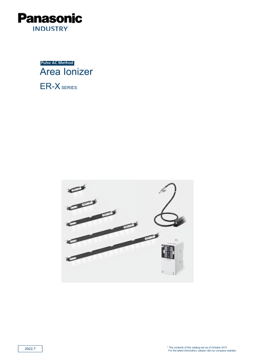
Pulse AC Method
Area Ionizer
ER-X SERIES
2022.7 * The contents of this catalog are as of October 2017.
For the latest information, please visit our company website.
Page2
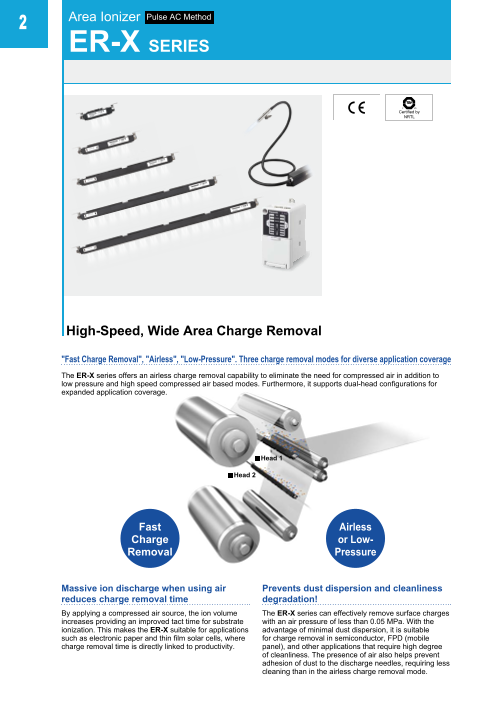
2 Area Ionizer Pulse AC Method
ER-X SERIES
Certified by
NRTL
High-Speed, Wide Area Charge Removal
"Fast Charge Removal", "Airless", "Low-Pressure". Three charge removal modes for diverse application coverage
The ER-X series offers an airless charge removal capability to eliminate the need for compressed air in addition to
low pressure and high speed compressed air based modes. Furthermore, it supports dual-head configurations for
expanded application coverage.
Head 1
Head 2
Fast Airless
Charge or Low-
Removal Pressure
Massive ion discharge when using air Prevents dust dispersion and cleanliness
reduces charge removal time degradation!
By applying a compressed air source, the ion volume The ER-X series can effectively remove surface charges
increases providing an improved tact time for substrate with an air pressure of less than 0.05 MPa. With the
ionization. This makes the ER-X suitable for applications advantage of minimal dust dispersion, it is suitable
such as electronic paper and thin film solar cells, where for charge removal in semiconductor, FPD (mobile
charge removal time is directly linked to productivity. panel), and other applications that require high degree
of cleanliness. The presence of air also helps prevent
adhesion of dust to the discharge needles, requiring less
cleaning than in the airless charge removal mode.
Page3
Area Ionizer ER-X SERIES 3
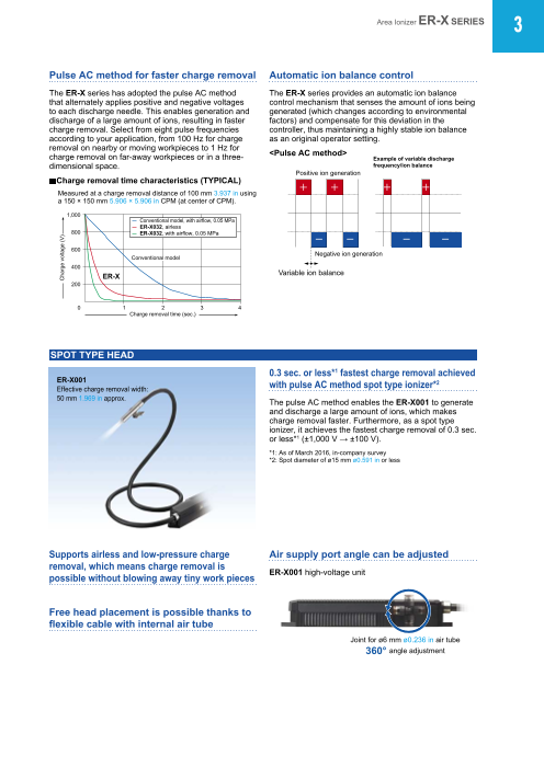
Pulse AC method for faster charge removal Automatic ion balance control
The ER-X series has adopted the pulse AC method The ER-X series provides an automatic ion balance
that alternately applies positive and negative voltages control mechanism that senses the amount of ions being
to each discharge needle. This enables generation and generated (which changes according to environmental
discharge of a large amount of ions, resulting in faster factors) and compensate for this deviation in the
charge removal. Select from eight pulse frequencies controller, thus maintaining a highly stable ion balance
according to your application, from 100 Hz for charge as an original operator setting.
removal on nearby or moving workpieces to 1 Hz for
charge removal on far-away workpieces or in a three- <Pulse AC method>
Example of variable discharge
dimensional space. frequency/ion balance
Positive ion generation
Charge removal time characteristics (TYPICAL)
Measured at a charge removal distance of 100 mm 3.937 in using
a 150 × 150 mm 5.906 × 5.906 in CPM (at center of CPM).
1,000
Conventional model, with airflow, 0.05 MPa
ER-X032, airless
800 ER-X032, with airflow, 0.05 MPa
600
Negative ion generation
Conventional model
400
ER-X Variable ion balance
200
0 1 2 3 4
Charge removal time (sec.)
SPOT TYPE HEAD
0.3 sec. or less*1 fastest charge removal achieved
ER-X001 2
Effective charge removal width: with pulse AC method spot type ionizer*
50 mm 1.969 in approx. The pulse AC method enables the ER-X001 to generate
and discharge a large amount of ions, which makes
charge removal faster. Furthermore, as a spot type
ionizer, it achieves the fastest charge removal of 0.3 sec.
or less*1 (±1,000 V → ±100 V).
*1: As of March 2016, in-company survey
*2: Spot diameter of ø15 mm ø0.591 in or less
Supports airless and low-pressure charge Air supply port angle can be adjusted
removal, which means charge removal is
possible without blowing away tiny work pieces ER-X001 high-voltage unit
Free head placement is possible thanks to
flexible cable with internal air tube
Joint for ø6 mm ø0.236 in air tube
360° angle adjustment
Charge voltage (V)
Page4
4 Area Ionizer ER-X SERIES
BAR TYPE HEAD
High and low temperature resistant type head also available
ER-X008 ER-X□HC
Effective charge removal width: Bar type head compatible with ambient temperatures of
80 mm 3.150 in approx. -60 to +200 °C -76 to +392 °F is available.
ER-X016
Effective charge removal width:
160 mm 6.299 in approx.
ER-X032
Effective charge removal width:
320 mm 12.598 in approx.
ER-X048
Effective charge removal width:
480 mm 18.898 in approx.
ER-X064
Effective charge removal width:
640 mm 25.197 in approx.
Super-compact slim head Discharge needle air barrier design for reduced contamination
By thoroughly redesigning the discharge needle, we A barrier of clean air around the discharge needle keeps
have created a super-compact slim head that combines foreign matter from adhering to it, preventing degraded
high-speed charge removal*1 with a maintenance-saving performance. Additionally, by using separate air sources
design*2. The ER-X series can be embedded in, or for the discharge needle barrier and ion transport, the
retrofitted onto, equipment that did not provide enough ER-X series keeps discharge from becoming unstable
space for antistatic measures in the past. due to pressure concentration, allowing the device to
*1: Pulse AC method with built-in air tubes (max. pressure 0.5 MPa) efficiently generate and transport ions.
*2: Discharge needle air barrier structure, discharge needle unit for
simple need replacement Air barrier Discharge needle after Efficient charge
structure protected by air barrier removal structure
(0.05 MPa) for one month
360-
Angle adjustment screw 30 mm degree
angle
(1.181 in) adjustment
22 mm
(0.866 in) Carefully designed to prevent
contamination in manufacturing processes
In consideration of the manufacturing process
(secondary cells etc.), the ER-X series heads neither
use copper nor plate processing. This minimizes the risk
of contamination with foreign substances.
Flat discharge surface for easy cleaning Discharge needle unit for simple needle replacement
The ER-X series heads have a flat discharge face, The removable discharge needle unit (including a set
allowing effortless cleaning of the discharge needles and of four needles) substantially simplifies maintenance.
air outlets by simply brushing along the groove provided. To remove the unit, just slide it toward both ends as
indicated by the arrows.
Discharge needles
Air outlets Discharge needle unit
Groove Commercial brush
Page5
Area Ionizer ER-X SERIES 5
CONTROLLER
Dual head configuration for enhanced charge area and layout expansion
1
controller + 2 heads
• D ifferent heads can be combined.
* T he new-type controller, ER-XC02, allows simultaneous connection of
the bar type head and spot type head.
• Charge removal is possible with a layout that places
heads on either side of the workpiece.
• The charge removal efficiency can be increased by
synchronizing the two heads.
Controller
High-voltage unit
ER-XC02
High-voltage unit
Head 1
Head 2
Equipped with charging function
The charging function is useful when charging paper or
parts for static electricity adsorption transport. Discharge indicator (green)
Notes: 1 ) Head 2 performs the ordinary charge neutralizing operation. Lights up during discharge.
2) T he ER-X001 cannot use the charging function.
(Discharge operation stops.) CHECK indicator (orange)
All-in-one model equipped with various Lights up when dirt, wear, etc. of the discharge
needle is detected.
functions for optimal removal of charge
ERROR indicator (red)
Level meter indicator (green) Lights up when abnormal discharge is detected.
Indicates static buildup around
the head or the amount of ion Discharge frequency setting switch
generated from the head. Select from eight ion generation frequencies ranging from
100 Hz to 1 Hz according to your application.
Head 1 can be used as a charger when the discharge
frequency setting switch for Head 1 is set to “+ Charge” or “-
Charge.”
Notes: 1) Head 2 performs the ordinary charge removal operation.
2) The ER-X001 cannot use the charging function.
(Discharge operation stops.)
Ion balance setting switch
Discharge control switch Adjust the ion balance to any of 15 levels according
Turn ion generation on and off. to the strength of the charge on the workpieces.
Various setting switch
• Check level changeover switch
SET UP button Set the maintenance notification level to
Determine the settings of “standard” or “high-sensitivity.”
discharge frequency and ion
balance. • Ion balance control switch
Enable or disable the ion balance auto control function.
• Indicator changeover switch
Set the level meter indicator display mode to “charge
strength display” or “ion generation volume display.”
• 2 heads control switch
Discharge control input Set the ion generation timing for the two heads to
Turn ion generation on and off “synchronize” or “inverse.”
from an external device. • Error output changeover switch
Alarm output, error output Set the error output condition to “generation of
Report maintenance timing and abnormal discharge” or “generation of abnormal
malfunctions to an external device. discharge + discharge stop setting ON.”
Page6
6 Area Ionizer ER-X SERIES
APPLICATIONS
Preventing electrostatic damage High-speed charge removal on a Airless charge removal of minute components
during bonding taping machine on a conveyor belt
Removal of static charges on laminate film Prevention of part feeder clogging High-speed charge removal on FPCs
Charge removal and dust removal Charge removal of molded plastic Charge removal and dust removal of
while separating TAB protective film components on a conveyor belt digital camera cases on a conveyor belt
Removing dust during instrument Removing dust during food Preventing adhesion of molded
panel assembly product cup transport parts to molds
High and low
temperature
resistant type
ER-X□HC
Page7
Area Ionizer ER-X SERIES 7
ORDER GUIDE
Heads Head connection cable is not supplied with the head. Please order it separately.
Type Appearance Charge removal time Effective charge
(±1,000 V→±100 V) Ion balance removal width Model No.
0.3 sec. or less
Spot type (Note 1), 50 mm 1.969 in ER-X001
0.5 sec. or less approx. (Note 4)
(Note 2)
ER-X008
(Note 4)
80 mm 3.150 in
High approx.
and low ER-X008HC
temperature (Note 5)
resistant
ER-X016
160 mm 6.299 in
High approx.
and low ER-X016HC
temperature (Note 5)
resistant
±30 V or less
(Note 2, 3)
ER-X032
Bar 1 sec. or less 320 mm 12.598 in
type High (Note 2) approx.
and low ER-X032HC
temperature (Note 5)
resistant
ER-X048
480 mm 18.898 in
High approx.
and low ER-X048HC
temperature (Note 5)
resistant
ER-X064
640mm 25.197 in
High approx.
and low ER-X064HC
temperature (Note 5)
resistant
Notes: 1) Typical value in condition of discharge distance 50 mm 1.969 in, center of the product, discharge frequency 50 Hz and air supply 60 ℓ/min. (0.3 MPa).
2) Typical value in condition of discharge distance 100 mm 3.937 in (ER-X001: 50 mm 1.969 in), center of the product, discharge frequency 50 Hz
(ER-X□HC: 30 Hz) and no air supply.
3) I on balance refers to the average value of plus and minus. The specification value is the typical one in condition used when ambient temperature
change is less than ±10 °C, ion balance is set after 30 minutes from the discharge start, the ion balance control function is set ON.
4) The ER-X001 and ER-X008 must be combined with the new-type ER-XC02 controller.
For the Identification of previous-type and new-type controllers and for the combination with the head, refer to p.16.
5) T he ER-X□HC high / low temperature resistant type head can be used under temperatures from -60 to +200 °C -76 to +392 °F. Be sure to use this head
in combination with the new-type controller, ER-XC02.
For the Identification of previous-type and new-type controllers and for the combination with the head, refer to p.16.
Page8
8 Area Ionizer ER-X SERIES
ORDER GUIDE
Controller Please order power cable or AC adapter separately.
Type Appearance Model No. Number of heads
connected Output
Standard
type ER-XC02 Max. 2 units PhotoMOS relay
Head connection cables Head connection cable is not supplied with the head. Please order it separately.
Appearance Model No. Description
ER-XCCJ2H Length: 2 m 6.562 ft, Net weight: 120 g approx.
ER-XCCJ5H Length: 5 m 16.404 ft, Net weight: 290 g approx. Cabtyre cable with
both connector
ER-XCCJ10H (Note) Length: 10 m 32.808 ft, Net weight: 560 g approx.
Note: Cannot be used with the high and low temperature resistant type head ER-X□HC.
OPTIONS
Power cable
Designation Model No. Description ER-XCC□
ER-XCC2 Length: 2 m 6.562 ft 0.15 mm2 10-core cabtyre cable
Net weight: 80 g approx.
Power cable with connector
Length: 5 m 16.404 ft Cable outer diameter: ø5.3 mm
ER-XCC5 Net weight: 190 g approx. ø0.209 in AC adapter
IN: 100-240 V AC, 50/60 Hz ER-XAPS-EX
ER-XAPS-EX OUT: 24 V DC, 1.5 A
Ambient temperature: 0 to +40 °C +32 to +104 °F
AC adapter Cable length between connector and AC adaptor: 1.8 m 5.905 ft
Ground wire: 3.7 m 12.139 ft ER-XAPS
ER-XAPS AC cable: 1 pc., Cable length 1.8 m 5.906 ft, Rating 125 V AC (Note 1)
Wiring connector terminals: 6 pcs.
CN-ACCN-C2 AC cable (conforming to CCC), Length: 2 m 6.562 ft
AC cable
CN-ACKR-C2 AC cable (conforming to KTL), Length: 2 m 6.562 ft Discharge needle unit
ER-XANT For ER-X016/X032/X048/X064. (Note 2) ER-XANT
Unit with replacement tungsten needles: 1 pc. ER-XANTHC
ER-XANT1 For ER-X001.
Unit with replacement tungsten needles: 1 pc.
Discharge For ER-X008. (Note 2)
needle unit ER-XANT2 Unit with replacement tungsten needles: 1 pc. ER-XANT1
ER-XANTHC For ER-X016HC/X032HC/X048HC/X064HC.
Unit with replacement tungsten needles: 1 pc.
ER-XANT2HC For ER-X008HC.
Unit with replacement tungsten needles: 1 pc.
ER-XANT2
For ER-X016/X032/X048/X064. (Note 2)
Enables to prevent electric shock by mounting to the heads. ER-XANT2HC
Discharge part ER-XACVR 2 pcs. per set. (Note 3)
protective cover Material: Polycarbonate, Weight: 20 g approx. (1 set)
* No effect on charge removal capacity of the heads by mounting a
discharge part protection cover
Notes: 1) Rating of the AC cable is 125 V AC. If the voltage used exceeds 125 V AC, prepare a proper cable
by yourself or purchase our optional cable CN-ACCN-C2 or CN-ACKR-C2. And, the AC cable is Discharge part protective cover
not enclosed with ER-XAPS-EX.
2) Cannot be used with the high and low temperature resistanttype head ER-X□HC. ER-XACVR
3) The number of set(s) you need depends on the head model No.
Model No. ER-X016 ER-X032 ER-X048 ER-X064
No. of set
(2 pcs per set) 1 set 2 sets 3 sets 4 sets
Page9
Area Ionizer ER-X SERIES 9
SPECIFICATIONS
Heads
Type Spot type Bar type
Item Model No. ER-X001 ER-X008 ER-X016 ER-X032 ER-X048 ER-X064
CE marking directive compliance EMC Directive, RoHS Directive
Effective charge removal width 50 mm 1.969 in approx. 80 mm 3.150 in approx. 160 mm 6.299 in approx. 320 mm 12.598 in approx. 480 mm 18.898 in approx. 640 mm 25.197 in approx.
Charge removal time 0.3 sec. or less (Note 1),
(±1,000 V→±100 V) 0.5 sec. or less (Note 2) 1 sec. or less (Note 2)
Ion balance ±30 V or less (Note 2, 3)
Discharge method Pulse AC method
Discharge frequency 50 Hz / 20 Hz 50 Hz / 30 Hz / 20 Hz
/ 10 Hz / 5 Hz / 1 Hz 100 Hz / 70 Hz / 50 Hz / 30 Hz / 20 Hz / 10 Hz / 5 Hz / 1 Hz (Note 4)
Discharge output voltage ±7,000 V approx.
Ozone generation 0.01 ppm or less (Note 2)
Maximum air pressure 0.5 MPa
Applicable fluid Air (dried clean air) (Note 5)
Operating altitude 2,000 m 6561.68 ft or less (Note 6)
Ambient temperature 0 to +50 °C +32 to +122 °F (ER-X001: 0 to +40 °C +32 to +104 °F) (No dew condensation allowed), Storage: -10 to +65 °C +14 to +149 °F
Ambient humidity 35 to 65 % RH, Storage: 35 to 85 % RH
Vibration resistance 10 to 55 Hz (ER-X001: 10 to 150 Hz) frequency, 0.75 mm 0.030 in double amplitude in X, Y and Z directions for two hours each
Shock resistance 100 m/s2 acceleration (10 G approx.), in X, Y and Z directions three times each
Enclosure grounding method Floating
Material Main unit enclosure: PPS, Stainless steal (SUS), Head mounting bracket: Stainless steal (SUS), Discharge needle: PC, PPS, Tungsten (Note 7)
[ER-X001 – Main unit enclosure: Stainless steel (SUS), Head mounting bracket: Stainless steel (SUS), Discharge needle: PFA, Tungsten]
Length of high-voltage cable 1.2 m 3.937 ft 0.5 m 1.640 ft 0.5 m 1.640 ft (Note 4)
Net weight 370 g approx. 330 g approx. 410 g approx. 530 g approx. 650 g approx. 780 g approx.
Accessory Head mounting bracket (mounted at the factory)
Type High and low temperature resistant
Item Model No. ER-X008HC ER-X016HC ER-X032HC ER-X048HC ER-X064HC
CE marking directive compliance EMC Directive, RoHS Directive
Effective charge removal width 80 mm 3.150 in approx. 160 mm 6.299 in approx. 320 mm 12.598 in approx. 480 mm 18.898 in approx. 640 mm 25.197 in approx.
Charge removal time
(±1,000 V→±100 V) 1 sec. or less (Note 2)
Ion balance ±30 V or less (Note 2, 3)
Discharge method Pulse AC method
Discharge frequency 30 Hz (Note 8)
Discharge output voltage ±7,000 V approx.
Ozone generation 0.01 ppm or less (Note 2)
Maximum air pressure 0.1 MPa
Applicable fluid Air (dried clean air) (Note 5)
Operating altitude 2,000 m 6561.68 ft or less (Note 6)
Ambient temperature Head: -60 to +200 °C -76 to +392 °F (No dew condensation or icing allowed) (Note 9), Storage: -10 to +65 °C +14 to +149 °F
High voltage unit: 0 to +50 °C +32 to +122 °F (No dew condensation allowed), Storage: -10 to +65 °C +14 to +149 °F
Ambient humidity 35 to 65 % RH, Storage: 35 to 85 % RH
Vibration resistance 10 to 55 Hz frequency, 0.75 mm 0.030 in double amplitude in X, Y and Z directions for two hours each
Shock resistance 100 m/s2 acceleration (10 G approx.), in X, Y and Z directions three times each
Enclosure grounding method Floating
Material Main unit enclosure: PPS, Stainless steal (SUS), Head mounting bracket: Stainless steal (SUS),
Discharge needle: PC, PPS, Tungsten, Main unit enclosure of high-voltage unit: ABS
Length of high-voltage cable Heat-resistant shielded cable, 1.8 m 5.906 ft long
Net weight 420 g approx. 490 g approx. 620 g approx. 760 g approx. 900 g approx.
Accessories ø6 ø0.236-4 air tube joint: 1 pc., Seal cap: 1 pc., Head mounting bracket (mounted at the factory)
Notes: 1) Typical value in condition of discharge distance 50 mm 1.969 in, center of the product, discharge frequency 50 Hz and air supply 60 ℓ/min.(0.3 MPa).
2) Typical value in condition of discharge distance 100 mm 3.937 in (ER-X001: 50 mm 1.969 in), center of the product, discharge frequency 50 Hz (ER-X□HC: 30 Hz) and no air supply.
3) Ion balance refers to the average value of plus and minus. The specification value is the typical one in condition used when ambient temperature
change is less than ±10 °C, ion balance is set after 30 minutes from the discharge start, the ion balance control function is set ON.
4) The high-voltage cable is also available in lengths of 1 m 3.281 ft and 2 m 6.562 ft. The discharge frequency of 1 m 3.281 ft / 2 m 6.562 ft cables is 50 /
30 / 20 / 10 / 5 / 1 Hz. For details, please contact our sales office.
5) The dried clean air is the air dried (dew point: equivalent of -20 °C -4 °F) and filtered (mesh-size: equivalent of 0.01 μm).
6) Do not use or store in an environment that has been pressurized to an air pressure higher than the atmospheric pressure at 0 m.
7) Silicon needles (ER-X016S, ER-X032S and ER-XANS) are also available. For details, please contact our sales office.
8) Set the discharge frequency to 30 Hz. Do not use any other frequency.
9) Discoloration of the head may occur when used under high temperatures, but it does not affect the charge removal performance.
Page10
10 Area Ionizer ER-X SERIES
SPECIFICATIONS
Allowable ambient temperature of high and low temperature resistant type head ER-X□HC and its installation
When installing, make sure to expose a section measuring 500 mm 19.685 in or more to the normal temperature area as
shown below for the protection of the high-voltage unit.
Allowable ambient temperature of the head Allowable ambient temperature of the high-voltage unit
-60 to +200 °C -76 to +392 °F 0 to +50 °C +32 to +122 °F
High-voltage unit
Head
500 mm
High-voltage cable (1.8 m 5.906 ft) 19.685 in Head connection cable (Note)
or more
Note: The high and low temperature resistant type ER-X□HC cannot be connected with the ER-XCCJ10H head connection cable (10 m 32.808 ft in length).
Controller
Type Controller
Item Model No. ER-XC02
CE marking directive compliance EMC Directive, RoHS Directive
Number of heads connected Maximum 2 units
Supply voltage 24 V DC ±10 %
Current consumption 450 mA or less when connecting 1 head, 800 mA or less when connecting 2 heads
Indicator Displays status of Head 1 and 2
DSC (Discharge) Green LED (lights up when discharging)
CHECK Orange LED (lights up when dirt, wear, etc. of the discharge needle is detected)
ERROR Red LED (lights up when abnormal discharge is detected)
Level meter Green LED (5 levels, lights up depending on amount of the charge or ion generation)
Output PhotoMOS relay output
ALARM • Maximum load current: 100 mA
ERROR • Applied voltage: 30 V DC or less (between output-output common)
COM (Common) • Residual voltage: 1.5 V or less (at 100 mA load current)
Output operation ALARM: ON when dirt or wear of the discharge needle is detected, OFF when operation is normal.
ERROR: OFF when abnormal discharge is detected, ON when operation is normal.
Short-circuit protection Incorporated (automatic reset type)
Discharge control input (DSC OFF) Discharge allowed: Open, Discharge halt: 24 V or 0 V shorted
Contamination level 2
Overvoltage category I
Elevation 2,000 m 6561.68 ft or less (Note)
Ambient temperature 0 to +50 °C +32 to +122 °F (No dew condensation allowed), Storage: –10 to +65 °C +14 to +149 °F
Ambient humidity 35 to 65 % RH, Storage: 35 to 85 % RH
Voltage withstandability 1,000 V AC for one min. between all supply terminals connected together and enclosure
500 V AC for on min. between supply terminals and F.G.
Insulation resistance 20 MΩ, or more, with 250 V DC megger between all supply terminals connected together and enclosure
Vibration resistance 10 to 150 Hz frequency, 0.75 mm 0.030 in double amplitude in X, Y and Z directions for two hours each
Shock resistance 100 m/s2 acceleration (10 G approx.) in X, Y and Z directions three times each
Enclosure grounding method Floating
Material Enclosure: ABS
Weight Net weight: 130 g approx.
Accessories Power supply / I/O connector: 1 set (Housing 5557-10R, Terminal 5556TL [manufactured by Molex])
Ground wire (3.7 m 12.139 ft approx.): 1 pc.
Note: Do not use or store in an environment that has been pressurized to an air pressure higher than the atmospheric pressure at 0 m.
Page11
Area Ionizer ER-X SERIES 11
CHARGE REMOVAL CHARACTERISTICS (TYPICAL) Please contact our office for details on data that is not listed here.
Measured using a 150 × 150 mm 5.906 × 5.906 in CPM (charge plate monitor). (At center of CPM)
Common to ER-X001/X008 ER-X001
Air flow Correlation between charge removal Correlation between charge removal
distance and charge removal time (50 Hz) distance and charge removal time (20 Hz)
100 10 10
─ ER-X001 ─ Airless ─ Airless
─ ER-X008 ─ 0.005 MPa ─ 0.005 MPa
80 8 ─ 0.1 MPa 8 ─ 0.1 MPa
─ 0.3 MPa ─ 0.3 MPa
─ 0.5 MPa ─ 0.5 MPa
60 6 6
Center CPM Center CPM
40 4 L 4 L
20 2 2
0 0.1 0.2 0.3 0.4 0.5 0 200 400 600 800 1,000 0 200 400 600 800 1,000
7.874 15.748 23.622 31.496 39.370 7.874 15.748 23.622 31.496 39.370
Applied pressure (MPa) Charge removal distance L (mm in) Charge removal distance L (mm in)
ER-X001
Charge removal field Charge removal field Charge removal field Charge removal field
(airless, 50 Hz) (airless, 20 Hz) (0.005 MPa, 50 Hz) (0.005 MPa, 20 Hz)
250 250 250 250
9.843 CPM 9.843 CPM 9.843 CPM 9.843
200
7.874 Center 200 200 200
+ 7.874 Center 7.874 Center 7.874
150 150 +
L 150 +
L 150
5.906 L − W 5.906 W 5.906 W 5.906
100 100 − 100 − 100
3.937 3.937 3.937 3.937
50 50 50 50
1.969 1.969 1.969 1.969 CPM
Center
0 0 0 0 +
−50 −50 −50 −50 L
−1.969 −1.969 −1.969 −1.969 − W
−100 −100 −100 −100
−3.937 −3.937 −3.937 −3.937
−150 ─ 1 sec. −150 ─ 1 sec. −150 ─ 1 sec. −150 ─ 1 sec.
−5.906 ─ 2 sec. −5.906 ─ 2 sec. −5.906 ─ 2 sec. −5.906 ─ 2 sec.
−200 ─ 5 sec. −200 ─ 5 sec. −200 ─ 5 sec. −200 ─ 5 sec.
−7.874 ─ 10 sec. −7.874 ─ 10 sec. −7.874 ─ 10 sec. −7.874 ─ 10 sec.
−250 −250 −250 −250
−9.843 0 50 100 150 200 250 −9.843 0 50 100 150 200 250 −9.843 0 50 100 150 200 250 300 350 −9.843 0 50 100 150 200 250 300 350
1.969 3.937 5.906 7.874 9.843 1.969 3.937 5.906 7.874 9.843 1.969 3.937 5.906 7.874 9.843 11.811 13.780 1.969 3.937 5.906 7.874 9.843 11.811 13.780
Charge removal distance L (mm in) Charge removal distance L (mm in) Charge removal distance L (mm in) Charge removal distance L (mm in)
ER-X001
Charge removal field Charge removal field
(0.5 MPa, 50 Hz) (0.5 MPa, 20 Hz)
250 250
9.843 CPM 9.843 CPM
200 Center 200 Center
7.874 + 7.874 +
150 L
5.906 − W 150 L
5.906 − W
100 100
3.937 3.937
50 50
1.969 1.969
0 0
−50 −50
−1.969 −1.969
−100 −100
−3.937 −3.937
−150 ─ 0.5 sec. −150 ─ 0.5 sec.
−5.906 ─ 1 sec. −5.906 ─ 1 sec.
−200 ─ 2 sec. −200 ─ 2 sec.
−7.874 ─ 5 sec. −7.874 ─ 5 sec.
−250 −250
−9.843 0 200 400 600 800 1,000 −9.843 0 200 400 600 800 1,000
7.874 15.748 23.622 31.496 39.370 7.874 15.748 23.622 31.496 39.370
Charge removal distance L (mm in) Charge removal distance L (mm in)
ER-X008
Correlation between charge removal Correlation between charge removal Charge removal field Charge removal field
distance and charge removal time (50 Hz) distance and charge removal time (10 Hz) (vertical direction, airless, 50 Hz) (vertical direction, airless, 10 Hz)
10 10 300 300
─ Airless ─ Airless 11.811 11.811
─ 0.005 MPa CPM
─ 0.005 MPa
8 ─ 0.1 MPa 8 ─ 0.1 MPa 200 Center + 200
─ 0.3 MPa ─ 0.3 MPa 7.874 L W 7.874
─ 0.5 MPa ─ 0.5 MPa −
100 100
6 CPM 6 3.937 3.937
CPM CPM
Center Center 0 0 Center +
4 L 4 L L − W
−100 −100
−3.937 −3.937
2 2 ─ 1 sec. ─ 1 sec.
−200 ─ 2 sec. −200 ─ 2 sec.
−7.874 ─ 5 sec. −7.874 ─ 5 sec.
─ 10 sec. ─ 10 sec.
0 200 400 600 800 1,000 0 200 400 600 800 1,000 −300 −300
−11.811 0 50 100 150 200 250 300 −11.811 0 50 100 150 200 250 300
7.874 15.748 23.622 31.496 39.370 7.874 15.748 23.622 31.496 39.370 1.969 3.937 5.906 7.874 9.843 11.811 1.969 3.937 5.906 7.874 9.843 11.811
Charge removal distance L (mm in) Charge removal distance L (mm in) Charge removal distance L (mm in) Charge removal distance L (mm in)
Charge removal time (sec.)
Charge removal width W (mm in) Charge removal width W (mm in) Air flow [ℓ/min. (ANR)]
Charge removal time (sec.) Charge removal width W (mm in) Charge removal width W (mm in) Charge removal time (sec.)
Charge removal width W (mm in) Charge removal width W (mm in) Charge removal time (sec.)
Charge removal width W (mm in) Charge removal width W (mm in)
Page12
12 Area Ionizer ER-X SERIES
CHARGE REMOVAL CHARACTERISTICS (TYPICAL) Please contact our office for details on data that is not listed here.
Measured using a 150 × 150 mm 5.906 × 5.906 in CPM (charge plate monitor). (At center of CPM)
ER-X008
Charge removal field Charge removal field Charge removal field Charge removal field
(vertical direction, 0.005 MPa, 50 Hz) (vertical direction, 0.005 MPa, 10 Hz) (vertical direction, 0.5 MPa, 50 Hz) (vertical direction, 0.5 MPa, 10 Hz)
300 300 300 300
11.811 CPM 11.811 CPM 11.811 CPM 11.811
Center Center
200 + 200 Center + 200 + 200
7.874 L W 7.874 L W 7.874 L W 7.874
− − −
100 100 100 100
3.937 3.937 3.937 3.937 CPM
0 0 0 0 Center +
L − W
−100 −100 −100 −100
−3.937 −3.937 −3.937 −3.937
─ 1 sec. ─ 1 sec. ─ 1 sec. ─ 1 sec.
−200 ─ 2 sec. −200 ─ 2 sec. −200 ─ 2 sec. −200 ─ 2 sec.
−7.874 ─ 5 sec. −7.874 ─ 5 sec. −7.874 ─ 5 sec. −7.874 ─ 5 sec.
─ 10 sec. ─ 10 sec. ─ 10 sec. ─ 10 sec.
−300 −300 −300 −300
−11.811 0 100 200 300 400 500 600 −11.811 0 100 200 300 400 500 600 −11.811 0 200 400 600 800 1,000 −11.811 0 200 400 600 800 1,000
3.937 7.874 11.811 15.748 19.685 23.622 3.937 7.874 11.811 15.748 19.685 23.622 7.874 15.748 23.622 31.496 39.370 7.874 15.748 23.622 31.496 39.370
Charge removal distance L (mm in) Charge removal distance L (mm in) Charge removal distance L (mm in) Charge removal distance L (mm in)
Common to ER-X016/X032/X048/X064
Air flow Correlation between charge removal Correlation between charge removal Correlation between charge removal
distance and charge removal time (50 Hz) distance and charge removal time (10 Hz) distance and charge removal time (1 Hz)
400 10 10 10
─ Airless ─ Airless ─ Airless
─ 0.005 MPa ─ 0.005 MPa ─ 0.005 MPa
─ ER-X064 8 ─ 0.1 MPa 8 ─ 0.1 MPa 8 ─ 0.1 MPa
300 ─ ER-X048 ─ 0.3 MPa ─ 0.3 MPa ─ 0.3 MPa
─ ER-X032 ─ 0.5 MPa ─ 0.5 MPa ─ 0.5 MPa
─ ER-X016 6 CPM 6 CPM 6 CPM
Center Center Center
200
4 L 4 L 4 L
100 2 2 2
0 0.1 0.2 0.3 0.4 0.5 0 200 400 600 800 1,000 1,200 1,400 1,600 0 200 400 600 800 1,000 1,200 1,400 1,600 0 200 400 600 800 1,000 1,200 1,400 1,600
7.874 15.748 23.622 31.496 39.370 47.244 55.118 62.992 7.874 15.748 23.622 31.496 39.370 47.244 55.118 62.992 7.874 15.748 23.622 31.496 39.370 47.244 55.118 62.992
Applied pressure (MPa) Charge removal distance L (mm in) Charge removal distance L (mm in) Charge removal distance L (mm in)
Common to ER-X016/X032/X048/X064
Charge removal field Charge removal field Charge removal field Charge removal field
(horizontal direction, airless, 50 Hz) (horizontal direction, airless, 10 Hz) (horizontal direction, airless, 1 Hz) (horizontal direction, 0.005 MPa, 50 Hz)
500 500 500 500
19.685 CPM 19.685 CPM 19.685 19.685 CPM
400 + 400
15.748 Center 15.748 Center + 400 400
15.748 15.748 Center +
W
300 W 300 W 300 300 −
11.811 L − 11.811 L − 11.811 11.811 L
200 200 200 200
7.874 7.874 7.874 CPM 7.874
100 100 100 100
3.937 3.937 3.937 Center +
W 3.937
0 0 0 − 0
L
−100 −100 −100 −100
−3.937 −3.937 −3.937 −3.937
−200 −200 −200 −200
−7.874 ─ 1 sec. −7.874 ─ 1 sec. −7.874 ─ 1 sec. −7.874
−300 −300 −300 −300 ─ 1 sec.
−11.811 ─ 2 sec. −11.811 ─ 2 sec. −11.811 ─ 2 sec. −11.811 ─ 2 sec.
−400 ─ 5 sec. −400 ─ 5 sec. −400 ─ 5 sec. −400 ─ 5 sec.
−15.748 ─ 10 sec. −15.748 ─ 10 sec. −15.748 ─ 10 sec. −15.748 ─ 10 sec.
−500 −500 −500 −500
−19.685 0 100 200 300 400 500 600 −19.685 0 100 200 300 400 500 600 −19.685 0 100 200 300 400 500 600 −19.685 0 200 400 600 800 1,000
3.937 7.874 11.811 15.748 19.685 23.622 3.937 7.874 11.811 15.748 19.685 23.622 3.937 7.874 11.811 15.748 19.685 23.622 7.874 15.748 23.622 31.496 39.370
Charge removal distance L (mm in) Charge removal distance L (mm in) Charge removal distance L (mm in) Charge removal distance L (mm in)
Common to ER-X016/X032/X048/X064
Charge removal field Charge removal field Charge removal field Charge removal field
(horizontal direction, 0.005 MPa, 10 Hz) (horizontal direction, 0.005 MPa, 1 Hz) (horizontal direction, 0.5 MPa, 50 Hz) (horizontal direction, 0.5 MPa, 10 Hz)
500 500 500 500
19.685 CPM 19.685 19.685 CPM 19.685 CPM
400 + 400 400 + 400 +
15.748 Center 15.748 15.748 Center 15.748 Center
300 W
L − 300 300 W 300 W
11.811 11.811 11.811 L − 11.811 L −
200 200 200 200
7.874 7.874
100 100 CPM 7.874 7.874
100 100
3.937 3.937 Center + 3.937 3.937
0 0 W 0 0
L −
−100 −100 −100 −100
−3.937 −3.937 −3.937 −3.937
−200 −200 −200 −200
−7.874 ─ 1 sec. −7.874 ─ 1 sec. −7.874 −7.874
−300 −300 −300 −300
−11.811 ─ 2 sec. −11.811 ─ 2 sec. −11.811 ─ 0.5 sec. −11.811 ─ 0.5 sec.
−400 ─ 5 sec. −400 ─ 5 sec. −400 ─ 1 sec. −400 ─ 1 sec.
−15.748 ─ 10 sec. −15.748 ─ 10 sec. −15.748 ─ 2 sec. −15.748 ─ 2 sec.
−500 −500 −500 −500
−19.685 0 200 400 600 800 1,000 −19.685 0 200 400 600 800 1,000 −19.685 0 200 400 600 800 1,000 1,200 1,400 1,600 −19.685 0 200 400 600 800 1,000 1,200 1,400 1,600
7.874 15.748 23.622 31.496 39.370 7.874 15.748 23.622 31.496 39.370 7.874 15.748 23.622 31.496 39.370 47.244 55.118 62.992 7.874 15.748 23.622 31.496 39.370 47.244 55.118 62.992
Charge removal distance L (mm in) Charge removal distance L (mm in) Charge removal distance L (mm in) Charge removal distance L (mm in)
Charge removal width W (mm in) Charge removal width W (mm in) Air flow [ℓ/min. (ANR)] Charge removal width W (mm in)
Charge removal width W (mm in) Charge removal width W (mm in) Charge removal time (sec.) Charge removal width W (mm in)
Charge removal width W (mm in) Charge removal width W (mm in) Charge removal time (sec.) Charge removal width W (mm in)
Charge removal width W (mm in) Charge removal width W (mm in) Charge removal time (sec.) Charge removal width W (mm in)
Page13
Area Ionizer ER-X SERIES 13
CHARGE REMOVAL CHARACTERISTICS (TYPICAL) Please contact our office for details on data that is not listed here.
Measured using a 150 × 150 mm 5.906 × 5.906 in CPM (charge plate monitor). (At center of CPM)
Common to ER-X016/X032/X048/X064 ER-X032
Charge removal field Charge removal field Charge removal field Charge removal field
(horizontal direction, 0.5 MPa, 1 Hz) (vertical direction, airless, 50 Hz) (vertical direction, airless, 10 Hz) (vertical direction, airless, 1 Hz)
500 500 500 500
19.685 19.685 CPM 19.685 CPM 19.685
400 400 400 400
15.748 15.748 Center + 15.748 Center + 15.748
300 300 300 300
11.811 11.811 L − W 11.811 L − W 11.811 ─ 1 sec.
200 200 200 200 ─ 2 sec.
7.874 7.874 7.874 7.874 ─ 5 sec.
100 CPM
+ 100 100 100 ─ 10 sec.
3.937 Center 3.937 3.937 3.937
0 W 0 0 0 CPM
L −
−100 −100 −100 −100 Center +
−3.937 −3.937 −3.937 −3.937 L
−200 −200 −200 −200 − W
−7.874 −7.874 −7.874 −7.874
−300 −300 ─ 1 sec. −300 ─ 1 sec. −300
−11.811 ─ 0.5 sec. −11.811 ─ 2 sec. −11.811 ─ 2 sec. −11.811
−400 ─ 1 sec. −400 ─ 5 sec. −400 ─ 5 sec. −400
−15.748 ─ 2 sec. −15.748 ─ 10 sec. −15.748 ─ 10 sec. −15.748
−500 −500 −500 −500
−19.685 0 200 400 600 800 1,000 1,200 1,400 1,600 −19.685 0 100 200 300 400 500 600 −19.685 0 100 200 300 400 500 600 −19.685 0 100 200 300 400 500 600
7.874 15.748 23.622 31.496 39.370 47.244 55.118 62.992 3.937 7.874 11.811 15.748 19.685 23.622 3.937 7.874 11.811 15.748 19.685 23.622 3.937 7.874 11.811 15.748 19.685 23.622
Charge removal distance L (mm in) Charge removal distance L (mm in) Charge removal distance L (mm in) Charge removal distance L (mm in)
ER-X032
Charge removal field Charge removal field Charge removal field Charge removal field
(vertical direction, 0.005 MPa, 50 Hz) (vertical direction, 0.005 MPa, 10 Hz) (vertical direction, 0.005 MPa, 1 Hz) (vertical direction, 0.5 MPa, 50 Hz)
500 500 500 500
19.685 CPM 19.685 CPM 19.685 19.685 CPM
400 Center 400 Center 400 400
15.748 + 15.748 + 15.748 15.748 Center +
300 L W 300 L W 300 300
11.811 − 11.811 − 11.811 11.811 L − W
200 200 200 200
7.874 7.874 7.874
100 100 100 CPM 7.874
100
3.937 3.937 3.937 Center + 3.937
0 0 0 L − W 0
−100 −100 −100 −100
−3.937 −3.937 −3.937 −3.937
−200 −200 −200 −200
−7.874 ─ 1 sec. −7.874 ─ 1 sec. −7.874 ─ 1 sec. −7.874
−300
−11.811 ─ 2 sec. −300
−11.811 ─ 2 sec. −300 ─ 2 sec. −300
−11.811 −11.811 ─ 0.5 sec.
−400 ─ 5 sec. −400 ─ 5 sec. −400 ─ 5 sec. −400 ─ 1 sec.
−15.748 ─ 10 sec. −15.748 ─ 10 sec. −15.748 ─ 10 sec. −15.748 ─ 2 sec.
−500 −500 −500 −500
−19.685 0 200 400 600 800 1,000 −19.685 0 200 400 600 800 1,000 −19.685 0 200 400 600 800 1,000 −19.685 0 200 400 600 800 1,000 1,200 1,400 1,600
7.874 15.748 23.622 31.496 39.370 7.874 15.748 23.622 31.496 39.370 7.874 15.748 23.622 31.496 39.370 7.874 15.748 23.622 31.496 39.370 47.244 55.118 62.992
Charge removal distance L (mm in) Charge removal distance L (mm in) Charge removal distance L (mm in) Charge removal distance L (mm in)
ER-X032 ER-X064
Charge removal field Charge removal field Charge removal field Charge removal field
(vertical direction, 0.5 MPa, 10 Hz) (vertical direction, 0.5 MPa, 1 Hz) (vertical direction, airless, 50 Hz) (vertical direction, airless, 10 Hz)
500 500 800 800
19.685 CPM 19.685 31.496 CPM 31.496 CPM
400 400
15.748 Center + 15.748 600 Center + 600 Center +
300 300 23.622 23.622
11.811 L − W 11.811 400 L − W 400 L − W
200 200 15.748 15.748
7.874 7.874 200 200
100 100 CPM
Center 7.874 7.874
3.937 3.937 +
0 0 L W 0 0
−100 −100 − −200 −200
−3.937 −3.937 −7.874 −7.874
−200 −200
−7.874 −7.874 −400 −400
−300 −300 −15.748 ─ 1 sec. −15.748 ─ 1 sec.
−11.811 ─ 0.5 sec. −11.811 ─ 0.5 sec. −600 ─ 2 sec. ─ 2 sec.
−400 ─ 1 sec. −400 ─ 1 sec. ─ 5 sec. −600 ─ 5 sec.
−15.748 ─ 2 sec. −15.748 ─ 2 sec. −23.622 ─ 10 sec. −23.622 ─ 10 sec.
−500 −500 −800 −800
−19.685 0 200 400 600 800 1,000 1,200 1,400 1,600 −19.685 0 200 400 600 800 1,000 1,200 1,400 1,600 −31.496 0 100 200 300 400 500 600 −31.496 0 100 200 300 400 500 600
7.874 15.748 23.622 31.496 39.370 47.244 55.118 62.992 7.874 15.748 23.622 31.496 39.370 47.244 55.118 62.992 3.937 7.874 11.811 15.748 19.685 23.622 3.937 7.874 11.811 15.748 19.685 23.622
Charge removal distance L (mm in) Charge removal distance L (mm in) Charge removal distance L (mm in) Charge removal distance L (mm in)
ER-X064
Charge removal field Charge removal field Charge removal field Charge removal field
(vertical direction, airless, 1 Hz) (vertical direction, 0.005 MPa, 50 Hz) (vertical direction, 0.005 MPa, 10 Hz) (vertical direction, 0.005 MPa, 1 Hz)
800 800 800 800
31.496 31.496 CPM 31.496 CPM 31.496 CPM
600 600 Center + 600 Center + 600 Center
23.622 23.622 23.622 23.622 +
400 400 L W 400 L W 400 L W
15.748 15.748 − 15.748 − 15.748 −
200 CPM 200 200 200
7.874 7.874 7.874 7.874
Center
0 + 0 0 0
L W
−200 − −200 −200 −200
−7.874 −7.874 −7.874 −7.874
−400 −400 −400 −400
−15.748 ─ 1 sec. −15.748 −15.748 −15.748
−600 ─ 2 sec. ─ 1 sec. ─ 1 sec. ─ 1 sec.
−23.622 ─ 5 sec. −600
−23.622 ─ 2 sec. −600 ─ 2 sec. −600 ─ 2 sec.
─ 10 sec. ─ 5 sec. −23.622 ─ 5 sec. −23.622 ─ 5 sec.
−800 −800 −800 −800
−31.496 0 100 200 300 400 500 600 −31.496 0 200 400 600 800 1,000 −31.496 0 200 400 600 800 1,000 −31.496 0 200 400 600 800 1,000
3.937 7.874 11.811 15.748 19.685 23.622 7.874 15.748 23.622 31.496 39.370 7.874 15.748 23.622 31.496 39.370 7.874 15.748 23.622 31.496 39.370
Charge removal distance L (mm in) Charge removal distance L (mm in) Charge removal distance L (mm in) Charge removal distance L (mm in)
Charge removal width W (mm in) Charge removal width W (mm in) Charge removal width W (mm in) Charge removal width W (mm in)
Charge removal width W (mm in) Charge removal width W (mm in) Charge removal width W (mm in) Charge removal width W (mm in)
Charge removal width W (mm in) Charge removal width W (mm in) Charge removal width W (mm in) Charge removal width W (mm in)
Charge removal width W (mm in) Charge removal width W (mm in) Charge removal width W (mm in) Charge removal width W (mm in)
Page14
14 Area Ionizer ER-X SERIES
CHARGE REMOVAL CHARACTERISTICS (TYPICAL) Please contact our office for details on data that is not listed here.
Measured using a 150 × 150 mm 5.906 × 5.906 in CPM (charge plate monitor). (At center of CPM)
ER-X064
Charge removal field Charge removal field Charge removal field
(vertical direction, 0.5 MPa, 50 Hz) (vertical direction, 0.5 MPa, 10 Hz) (vertical direction, 0.5 MPa, 1 Hz)
800 800 800
31.496 CPM 31.496 CPM 31.496
600 Center + 600 Center
23.622 23.622 + 600
23.622
400 L − W 400 L W 400
15.748 15.748 − 15.748
200 200 200
7.874 7.874 7.874 CPM
Center
0 0 0 +
L W
−200 −200 −200 −
−7.874 −7.874 −7.874
−400 −400 −400
−15.748 −15.748 −15.748
−600 ─ 0.5 sec. −600 ─ 0.5 sec.
─ 1 sec. ─ 1 sec. −600 ─ 0.5 sec.
−23.622 ─ 2 sec. −23.622 ─ 1 sec.
─ 2 sec. −23.622 ─ 2 sec.
−800 −800 −800
−31.496 0 200 400 600 800 1,000 1,200 1,400 1,600 −31.496 0 200 400 600 800 1,000 1,200 1,400 1,600 −31.496 0 200 400 600 800 1,000 1,200 1,400 1,600
7.874 15.748 23.622 31.496 39.370 47.244 55.118 62.992 7.874 15.748 23.622 31.496 39.370 47.244 55.118 62.992 7.874 15.748 23.622 31.496 39.370 47.244 55.118 62.992
Charge removal distance L (mm in) Charge removal distance L (mm in) Charge removal distance L (mm in)
Common to ER-X□HC ER-X008HC ER-X016HC
Air flow Correlation between charge removal Correlation between charge removal
distance and charge removal time (30 Hz) distance and charge removal time (30 Hz)
100 10 10
─ ER-X064HC ─ Airless ─ Airless
─ ER-X048HC ─ 0.005 MPa ─ 0.005 MPa
80 ─ ER-X032HC 8 ─ 0.05 MPa 8 ─ 0.05 MPa
─ ER-X016HC ─ 0.1 MPa ─ 0.1 MPa
─ ER-X008HC
60 6 6
40 4 4
20 2 CPM CPM
Center 2
Center
L L
0 0.02 0.04 0.06 0.08 0.1 0 200 400 600 800 1,000 0 200 400 600 800 1,000
7.874 15.748 23.622 31.496 39.370 7.874 15.748 23.622 31.496 39.370
Applied pressure (MPa) Charge removal distance L (mm in) Charge removal distance L (mm in)
Please contact our office for details on data that is not listed here.
Air flow [ℓ/min. (ANR)] Charge removal width W (mm in)
Charge removal time (sec.) Charge removal width W (mm in)
Charge removal time (sec.) Charge removal width W (mm in)
Page15
Area Ionizer ER-X SERIES 15
I/O CIRCUIT AND WIRING DIAGRAMS
New-type controller (produced from April 2014 on)
Notice: Products manufactured from April 2014 and before April 2016 cannot be used with the high and low temperature resistant type head ER-X008HC.
For the Identification of previous-type and new-type controllers and for the combination with the head, refer to p.16.
Power connector terminal arrangement When connecting the output to negative common When connecting the output to positive common
(Brown) +V (Brown) +V
6 6
1 2 3 4 5
COM(+) 7 COM(+)
7
(Violet) COM (OUT) *1 (White) COM (IN)
6 7 8 9 10 8
4
3 (Pink) Discharge control input
(Orange) Alarm output
9 Load + 24 V DC
(Front view) (Black) Error output – ±10 % + 24 V DC
10 Load (Orange) Alarm output *2
– ±10 %
3 (Pink) Discharge control input 9 Load
Housing: 5569-10A (White) COM (IN) (Black) Error output
10
[Manufactured by Molex] 8 Load
(Blue) 0 V (Violet) COM (OUT)
1 4
Terminal Terminal Color 2 COM(─) (Blue) 0 V
1
No. name code 2
5 COM(─)
1 0 V Blue (Green/Yellow) F.G. Be sure to ground.
5 Be sure to ground.
2 COM(–) – Internal circuit User’s circuit (Green/Yellow) F.G.
Discharge Internal circuit User’s circuit
3 control input Pink *1 *2
4 COM(OUT) Violet
Non-voltage contact or Non-voltage contact or
5 F.G. terminal Green / Yellow PNP open-collector transistor NPN open-collector transistor
6 24 V Brown
7 COM(+) –
8 COM(IN) White or or
9 Alarm output Orange
10 Error output Black Contact “closed” or transistor ON: Discharge halt Contact “closed” or transistor ON: Discharge halt
Note: C olor code refers to cable colors Contact “open” or transistor OFF: Starting discharge Contact “open” or transistor OFF: Starting discharge
of an optional power supply
cable. Notes: 1) B e sure to ground the F.G. terminal. If F.G. terminal is not connected properly, it may cause electric shock.
In the case of ER-X001, the head mounting bracket and F.G. terminal are internally connected.
2) T o stop discharge, turn ON the discharge control input for 20 ms or longer. To start discharge, turn OFF
(open) the discharge control input. Discharge will start in 20 ms.
Previous-type controller (produced before March 2014)
Notice: Products manufactured before March 2014 cannot be used with ER-X001, ER-X008 and the high and low temperature resistant type
head ER-X□HC.
For the Identification of previous-type and new-type controllers and for the combination with the head, refer to p.16.
Power connector terminal arrangement When connecting the output to negative common When connecting the output to positive common
(Brown) +V (Brown) +V
6 6
1 2 3 4 5 7 COM(+) 7 COM(+)
(Violet) COM (OUT)
6 7 8 9 10 *1
4 3
(Orange) Alarm output (Pink) Discharge control input
9 Load
+ 24 V DC *2 + 24 V DC
(Front view) (Black) Error output Load ±10 % (Orange) Alarm output
10 – 9 Load – ±10 %
3 (Pink) Discharge control input (Black) Error output
Housing: 5569-10A 10 Load
[Manufactured by Molex] (Violet) COM (OUT)
4
(Blue) 0 V (Blue) 0 V
Terminal Terminal Color 1 1
2 COM(─) 2
No. name code COM(─)
5 5
(Green/Yellow) F.G. Be sure to ground. (Green/Yellow) F.G. Be sure to ground.
1 0 V Blue
2 COM(–) – Internal circuit User’s circuit Internal circuit User’s circuit
3 Discharge *1 *2
control input Pink
4 COM(OUT) Violet Non-voltage contact or Non-voltage contact or
5 F.G. terminal Green / Yellow PNP open-collector transistor NPN open-collector transistor
6 24 V Brown
7 COM(+) – or or
8 – White
9 Alarm output Orange Contact “closed” or transistor ON: Discharge halt Contact “closed” or transistor ON: Discharge halt
10 Error output Black Contact “open” or transistor OFF: Starting discharge Contact “open” or transistor OFF: Starting discharge
Note: C olor code refers to cable colors
of an optional power supply Notes: 1) Be sure to ground the F.G. terminal. If F.G. terminal is not connected properly, it may cause electric shock.
cable. 2) T o stop discharge, turn ON the discharge control input for 20 ms or longer. To start discharge, turn OFF
(open) the discharge control input. Discharge will start in 20 ms.
Main circuit Main circuit
Main circuit Main circuit
Page16
16 Area Ionizer ER-X SERIES
PRECAUTIONS FOR PROPER USE
• When using as a CSA and UL compliant product, use a CLASS 2 CSA/
• Never use this product as device for personnel protection. UL certified power supply, or a CSA/UL certified power supply that
• In case of using devices for personnel protection, use has been evaluated as a Limited Power Source as specified in CAN/
products which meet laws or standards, such as OSHA, CSA-C22.2 No.60950-1/UL60950-1.
ANSI or IEC etc., for personnel protection applicable in • This product has been developed / produced for industrial use only.
each region or country. • Do not use this product for purposes other than electric charge removal.
• This product produces high voltages. • Do not use this product in environments which are outside the
• Do not use this product in places where there may be a specification range, otherwise operating problems or damage may occur.
danger of flammable or combustible items being present. In addition, the operating life of the product may become significantly
• To prevent electric shock and to conduct proper reduced.
discharge, be sure to ground a frame ground (F.G.) • This product is a precision device. Do not apply a shock to it by dropping,
terminal of a controller. for example. Accidents or operating problems may occur.
• Do not place hands near the discharge needle. Doing so • Never disassemble, repair or modify this product. Accidents or operating
may cause electric shock. problems may occur.
• Since the tip of the discharge needle is sharp, take • Do not throw this product in fire. It may explode or toxic fumes may be
sufficient care in handling the discharge needle, or generated.
injuries may result. • Do not run the wires together with high-voltage lines or power lines or put
them in the same raceway. This can cause malfunction due to induction.
• The high-voltage cable between the head and the high-
voltage unit must be fixed and the minimum bend radius • Verify that the supply voltage variation is within the rating.
is less than R30 mm R1.181 in. In case of using at the • In case using switching regulator, be sure to connect F.G. terminal.
bend radius R30 mm R1.181 in or less and using at • When connecting / removing the head or performing wiring or inspection
moving part may cause fire and break down, etc. of the work, be sure to turn off the power first. Not doing so may result in
high-voltage cable. accidents, electric shock or operating problems.
• Clean the discharge needle regularly (about once a • After connecting the cables, check that the connections are correct before
week). Otherwise, optimum charge removal performance turning on the power. If the cables are connected incorrectly, operating
may not be achieved, and accidents or operating problems or accidents may occur.
problems may occur. • Do not use a cable with any damage such as cracks or splitting. Risk of
accidents and failure.
• If this product is used in a confined space, ozone emitted
from this product may be detrimental. Be sure to provide • Avoid use in a location with significant steam or dust, or in a location
where the product may come in direct contact with water, oil, or welding
ventilation. spatter.
• Do not direct ionized air toward the face. Ozone may • Do not touch the discharge needle with hard objects such as tools. If the
cause irritation to places such as the nose and throat. discharge needle becomes broken, it will not provide sufficient charge
• When the product has been used under very high or low removal performance, and moreover operating problems or accidents
temperatures, do not touch the product with a bare hand. may occur.
Failure to observe this caution can result in burn or injury. • During installation, fasten the product securely. If it is not securely
Be sure to let the product cool sufficiently when touching fastened or it is subjected to continuous vibration or shock, accidents or
the product for maintenance or other purposes. operating problems may result.
• Power cable that are 0.15mm2 or more and 30 m 98.425 ft or less in total
length for wiring. Also, keep the wiring as short as possible in order to
• NRTL (National Recognized Testing Laboratories) certification means prevent noise.
that the product was tested by the third-party private testing organization
(TÜV SÜD America) authorized by the Occupational Safety and Health • When disposing of this product, treat it appropriately as industrial waste.
Administration (OSHA) and found to comply with the safety standards • After starting discharge, it takes 30 minutes approx. for charge removal
(ANSI/UL) established by American National Standards Institute and the performance to stabilize. Therefore, wait 30 minutes before adjusting ion
standards (CAN/CSA) established by Canadian Standards Association. balance.
• Use the correct combination of head, discharge needle unit and controller.
Identification of previous-type and new-type controllers and combination with the head
New-type controller (Note) Previous-type controller (Note)
Produced from April Produced from April 2014
2016 on and before April 2016 Produced before March 2014
• Front nameplate • Front nameplate
Front ER-XC02 ER-XC02
DSC DSC
nameplate CHECK CHECK
Combination ERROR ERROR
HEAD HEAD HEAD HEAD
1 + + 2 Change 1 + + 2
0 0 of front 0 0
nameplate
- - design - -
• Bottom nameplate • Bottom nameplate • Bottom nameplate
Bottom nameplate
mark indicated mark not indicated mark not indicated
Spot type ER-X001 OK OK Cannot be used
ER-X008 Cannot be used
ER-X016
Bar type ER-X032 OK OK
OK
ER-X048
Head ER-X064
ER-X008HC Cannot be used
High and Low ER-X016HC
temperature ER-X032HC OK Cannot be used
resistant OK
ER-X048HC
ER-X064HC
Note: The layout of the power supply connector pins differ between new-type controllers and previous-type controllers.
For details refer to “I/O CIRCUIT AND WIRING DIAGRAMS” (p.15).
Page17
Area Ionizer ER-X SERIES 17
PRECAUTIONS FOR PROPER USE
Mounting Controller installation
Angle
Head installation adjustment screw • Mount the controller on a 35 mm 1.378 in width DIN rail or using
M4 screws.
• Using two M4 screws or one M6 screw, M4
screw <When mounting on a DIN rail>
mount the head onto the equipment housing.
• Loosen the angle adjustment screw, • Pull the lock release lever to Lock release lever
Angle
adjust the head angle, and then fasten the adjustment screw remove this product from the
head with the tightening torque of 0.5 N∙m DIN rail.
M6
or less. screw
• Position the head mounting bracket of the 35 mm 1.378 in
ER-X001 at least 20 mm 0.787 in away M4 screw width DIN rail
from the tip of the head. The tightening Head <When mounting using M4 screws>
torque for the head fixing screw must be fixing
screw • The tightening torque should be M4 screw
0.5 N∙m or less. 1.2 N∙m or less.
• After mounting and setting up the head,
set the controller according to the procedures described in the
instruction manual in order to properly remove electrical charge.
Notes: 1) B e sure to ground the equipment housing onto which the head is
mounted.
2) The distance between the head and the charge removing object
should be 30 mm 1.181 in or more. Piping
If the static buildup of the charge removing object is 30 kV or more,
set the distance to 50 mm 1.969 in or more. • Air supplied to this product will reduce contamination of the
3) If there is metal near the head or between the head and the charge discharge needle and improve the charge removal speed.
removing object, ion is absorbed, hindering appropriate static • The outer diameter of the air tube to fit to the air inlet portion of
removal. Install the head under the following installation condition.
4) In case using the side mounting, the discharge frequency should this product should be ø6 mm ø0.236 in.
be 10 Hz or more. • Make sure that clean air (air containing no water, no oil and no
• Back-side mounting (All frequencies) • Side mounting (10 Hz or more) dust) should be supplied.
50 mm Surrounding 50 mm Surrounding • Mounting of ER-X001
1.969 in or more metal 1.969 in or more metal • Since the pressure will drop when the air piping from the main
pressure supply is extended or pneumatic components (e.g.,
needle valve, speed controller, mini filter) are added, keep an
20 mm 20 mm eye on the pressure supply to the ionizer making sure it is not in
The discharge 0.787 in
muzzle must 0.787 in
or more short supply. For the pneumatic components, select those that
exceed this line or more can accommodate the air supply flow rate.
(surrounding metal.)
5) When installing two or more heads set the same frequency and
keep the distance as below. In face to face or parallel using ER-X008/X016/X032/X048/X064
different frequency, keep the distance between the heads 400 mm <Connection of pipe to head section>
15.748 in or more.
When installing the heads face to face, install heads in distance Head section
Air inlet
that the heads can perform the charge removal of a side of the
object individualy.
• Face-to-face installation
ø6 mm ø0.236 in tube
100 mm 11.4 mm 0.449 in
100 mm 3.937 in
3.937 in or more
or more ER-X008HC/X016HC/X032HC/X048HC/X064HC
<Connection of pipe to head section>
• Parallel installation
ø6 mm ø0.236 in Head section
heat-resistant tube
50 mm
50 mm 1.969 in 1.969 in ø6 ø0.236-4 air tube joint
or more or more
High-voltage unit installation Insert all the way
• Use two M4 screws or two M6 screws M6 screw ER-X001
to fasten the head. The tightening M4 screw
<Connection to high-voltage unit>
torques for fastening, are as follows. High-voltage unit
• When using M4 screws: 1.2 N∙m
• When using M6 screws: 2.5 N∙m
Notes: 1) Do not place any objects on top of the
high-voltage unit. ø6 mm ø0.236 in tube
2) When using multiple heads, keep the Air inlet
distance of at least 10 mm 0.394 in
between the high-voltage units.
3) When fastening the high-voltage 10 mm
0.394 in
unit using M6 screws, fasten before or more (11.6 mm 0.457 in)
connecting the head connection cable.
4) Use M6 screws for the installation of the high-voltage unit of the
ER-X001. Note: A fter inserting the tube into the joint of this product, always make sure
5) The minimum bending radius of the high-voltage cable is R30 mm that the tube is all the way in and securely inserted. Insufficient tube
R1.181 in. insertion will cause air leakage.
Page18
18 Area Ionizer ER-X SERIES
DIMENSIONS (Unit: mm in) The CAD data can be downloaded from our website.
ER-X008/X016/X032/X048/X064 Head
28.5 Joint for ø6 ø0.236 air tube
1.122
ø6.9 ø0.272 high-voltage cable 0.5 m 1.640 ft 9.4 B 28.5
6 0.370 1.122
0.236 180 7.087 40 A 9.4
2-ø6.5 ø0.256 17 1.575 40 0.370
mounting holes 0.669 160 6.299 1.575
28 1.102 18
0.709 9.5 0.374
Clean air outlet (4 points)
5 2-ø4.5 ø0.177 Points of discharge
31
0.197 mounting holes needle ion air outlet
1.220
(E)
2-ø6.5
38 ø0.256 D
1.496 10.5 170 6.693
0.413 ø12 18 4.2 C
18 30 1.181 22
162 6.378 ø0.472 0.709 0.165 0.866
0.709
35 28.4
1.378 (25 0.984) 1.118 9.4
0.370 Head mounting bracket Head mounting bracket 18
6 6.2 0.709
192 7.559 Discharge needle unit
0.236 0.244
12-pin connector
Details of a head mounting bracket Model No. A B C D (E)
2-ø6.5 ER-X008 40 1.575 106 4.173 138 5.433 150 5.906 163 6.417
ø0.256 4.2
9.4 0.370 0.165 ER-X016 120 4.724 194 7.638 226 8.898 238 9.370 251 9.882
ER-X032 280 11.024 354 13.937 386 15.197 398 15.669 411 16.181
18
0.709 ER-X048 440 17.323 514 20.236 546 21.496 558 21.969 571 22.480
6.2
0.244 ER-X064 600 23.622 674 26.535 706 27.795 718 28.268 731 28.780
Mounting drawing with discharge part protective cover (ER-XACVR)
Discharge part protective cover 18
0.709 Model No. (F)
45.7 ER-X016 159.6 6.283
1.799
15.7 0.618 ER-X032 319.6 12.583
159.6 6.283
(160 6.299) ER-X048 479.6 18.882
18
(F) 0.709 ER-X064 639.6 25.181
25.4
1.000
Note: The ER-XACVR discharge part protective cover cannot be used on the ER-X008 or high and low temperature resistant type head ER-X□HC.
ER-X008HC/X016HC/X032HC/X048HC/X064HC Head
Allowable ambient temperature: -60 to +200 °C -76 to +392 °F
ø6.9 ø0.272 heat-resistant
28.5 high-voltage cable (1.8 m 5.906 ft) ø6 ø0.236-4 air tube joint (accessory) 28.5
1.122 B 1.122
6 9.4 9.4
2-ø6.5 ø0.256 0.236 180 7.087
17 0.370 40 A 0.370
mounting holes 160 6.299 1300 1.575 40 6.9 10
0.669 51.181 1.575 0.272 0.394
28 1.102 18
0.709 9.5 0.374
Points of discharge Clean air outlet (4 points)
5 2-ø4.5 ø0.177 31 needle ion air outlet
0.197 mounting holes 1.220
(E)
2-ø6.5
38 ø0.256 D 22
10.5 170 6.693 C 0.866
1.496 ø12 18 4.2
18 0.413 0.709 30 1.181 4
0.709 162 6.378 ø0.472 0.165 0.157
35
1.378 (25 0.984) 28.4 1.118 9.4
0.370 Head mounting bracket Head mounting bracket
6.2
192 7.559 6 Discharge needle unit 18
0.236 0.244 0.709
12-pin connector
Details of a head mounting bracket Model No. A B C D (E)
2-ø6.5
ø0.256 ER-X008HC 40 1.575 106 4.173 138 5.433 150 5.906 163 6.417
4.2
9.4 0.370 0.165 ER-X016HC 120 4.724 194 7.638 226 8.898 238 9.370 251 9.882
18 ER-X032HC 280 11.024 354 13.937 386 15.197 398 15.669 411 16.181
0.709
ER-X048HC 440 17.323 514 20.236 546 21.496 558 21.969 571 22.480
6.2
0.244 ER-X064HC 600 23.622 674 26.535 706 27.795 718 28.268 731 28.780
Page19
Area Ionizer ER-X SERIES 19
DIMENSIONS (Unit: mm in) The CAD data can be downloaded from our website.
ER-X001 Head
ø10.5 ø0.413 high-voltage cable 1.2 m 3.937 ft long 28.5
(internal air tube) 1.122 12 0.472
8.6 20 16 M3 fixing screw
6 0.236 210 8.268 0.339 0.787 0.630
20
48 0.787
1.890
6.2 0.244
4.2
2-6.5 0.256 (17 0.669) 0.165
mounting holes (20.5 0.807)
Joint for ø6 ø0.236 air tube 70
2.756
(360° rotatable) 44
1.732
38 24 Mountable range
210
1.496 10.5
0.413 8.268 ø35 ø17 0.945 of head mounting
ø13 ø12
18 ø1.378 ø0.669 bracket
0.709 ø0.512 ø0.472
6
0.236
35
1.378 25 18 0.709
0.984 Discharge
14 8 needle unit
21.5 6 0.551 0.315
0.846 0.236 Head mounting bracket
165 6.496 25.4 (removable) Ion air outlet
1.000
222 8.740
ER-XC02 Controller ER-XCCJ□H Head connection cable
16
0.630 • Length L
16
0.630 L
For head 1 9.1 ø6 (9.1 0.358) Model No. Length L
0.358 ø0.236
44 For head 2 14 14 2,000
0.551 0.551 ER-XCCJ2H
1.732 78.740
ER-XCCJ5H 5,000
196.850
Head connection connector
9.3 S12B-PUDSS-1 [Manufactured by JST Mfg. Co., Ltd.] 8.8 8.8 10,000
0.336 0.346 0.346 ER-XCCJ10H 393.701
5.2
0.205 18
0.709
53 2.087 ER-XCC□ Power cable (Optional)
6.5 39 1.535
0.256 Suitable for 35 mm 1.378 in width DIN rail
7 7 10 19.6 L • Length L
0.276 0.276 0.394 (103.5 4.075) 0.772 ø5.3
ø0.209 Model No. Length L
22.2
27.3 0.874
ER-XCC2 2,000
1.075 78.740
76 14.4
2.992 35.4 0.567 ER-XCC5 5,000
196.850
97
3.189 1.394 90
3.543
140
5.512 ER-XAPS(-EX) AC adapter (Optional)
F.G. wire 3.7 m 12.139 ft
4 2-ø5 ø0.197 14.4
0.157 mounting holes 0.567 AC cable
1.8 m 5.910 ft (Note)
28
1.102
Cable
(22.2 0.874) 1.8 m 95.9
60 5.910 ft 3.776
2.362
16.5 43.8
0.650 Power supply connection connector 1.724
9.2 0.362 5569-10A [Manufactured by Molex] (19.6 0.772)
23.2
0.913 Note: The AC cable is not enclosed with ER-XAPS-EX.
Page20
Disclaimer
The applications described in the catalog are all intended for examples only. The purchase of our products described in the catalog shall not be
regarded as granting of a license to use our products in the described applications. We do NOT warrant that we have obtained some
intellectual properties, such as patent rights, with respect to such applications, or that the described applications may not infringe any
intellectual property rights, such as patent rights, of a third party.
Panasonic Industry Co., Ltd.
Industrial Device Business Division
7-1-1, Morofuku, Daito-shi, Osaka 574-0044, Japan
industrial.panasonic.com/ac/e/
ⓒ Panasonic Industry Co., Ltd. Specifications are subject to change without notice. 2022.7
Printed in Japan