


XTLseries
Product Catalog
Document Information
| Document Title | XTLseries |
|---|---|
| Document Type | Product Catalog |
| File size | 11.5Mb |
| Company | TAKAMAZ (TAKAMATSU MACHINERY Co.,ltd) (Documents List) |
Documents related to this company


Document Contents
Page1
English
Head Office and Plant
■TAKAMATSU MACHINERY CO., LTD.
・ HEAD OFFICE & PLANT
1-8 ASAHIGAOKA HAKUSAN-CITY ISHIKAWA JAPAN. 924-8558
TEL +81-(0)76-207-6155 FAX +81-(0)76-274-1418
・ ASAHI PLANT
4-13 ASAHIGAOKA HAKUSAN-CITY ISHIKAWA JAPAN. 924-0004
TEL +81-(0)76-274-0123 FAX +81-(0)76-274-8530
Overseas Bases
■TAKAMATSU MACHINERY U.S.A., INC.
・ CHICAGO HEAD OFFICE
1280 LANDMEIER ROAD ELK GROVE VILLAGE, IL 60007 USA
TEL +1-(0)847-981-8577 FAX +1-(0)847-981-8599
■TAKAMAZ MACHINERY EUROPE GmbH
IM HÜLSENFELD 19, 40721 HILDEN, GERMANY
TEL +49-(0)2103-789-4882 FAX +49-(0)2103-789-4883
■TAKAMAZ MACHINERY( HANGZHOU) CO., LTD.
・ HANGZHOU HEAD OFFICE
NO.6800, JIANGDONG 3RD ROAD, JIANGDONG INDUSTRIAL PARK,
XIAOSHAN, HANGZHOU, ZHEJIANG, CHINA
TEL +86(- 0)571-8287-9709 FAX +86(- 0)571-8215-3732
■TAKAMATSU MACHINERY( THAILAND) CO., LTD.
・ BANGKOK HEAD OFFICE
888/59 MOO 9, TAMBOL BANGPLA, AMPHUR BANGPLEE,
SAMUTPRAKARN PROVINCE, THAILAND
TEL +66(- 0)2-136-7831 FAX +66(- 0)2-136-7834
■PT. TAKAMAZ INDONESIA
JL. FESTIVAL BOULEVARD BLOK AA 11 NO.30,31 GRAND WISATA TAMBUN, BEKASI 17510 SERIES
TEL +62-(0)21-8261-6431 FAX +62-(0)21-8261-6430
■TAKAMAZ MACHINERY MEXICO, S.A.DE C.V.
AVENIDA DE LOS INDUSTRIALES 522, LOCAL 4, INDUSTRIAL JULIAN DE OBREGON, CNC PRECISION LATHE
37290 LEON, GUANAJUATO MEXICO
TEL +52-477-784-0468
■TAKAMATSU MACHINERY VIETNAM CO., LTD
NO.76 M HOANG QUOC VIET, PHU MY WARD, DISTRICT 7, HO CHI MINH CITY, VIETNAM
TEL +84-(0)28-3620-5671 FAX +84-(0)28-3620-5673
Affiliated Companies
■HANGZHOU FEELER TAKAMATSU MACHINERY CO., LTD.
NO.6800, JIANGDONG 3RD ROAD, JIANGDONG INDUSTRIAL PARK,
XIAOSHAN, HANGZHOU, ZHEJIANG, CHINA
TEL +86(- 0)571-8215-3760 FAX +86(- 0)571-8286-5311
Scan this QR Code
for more details.
25.08.1.5B(O)
Page2
WHERE TO CHOOSE PERFORMANCE OPERABILITY CUSTOMISE FITTINGS MAINTENANCE DATA
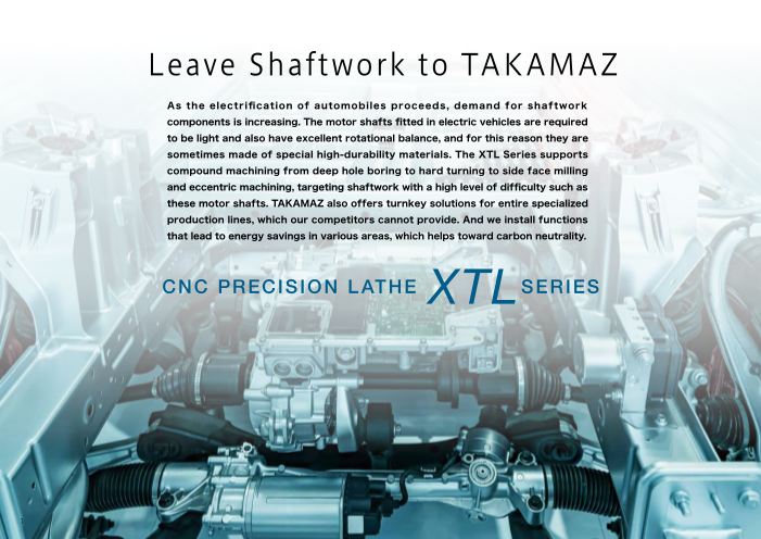
Leave Shaftwork to TAKAMAZ
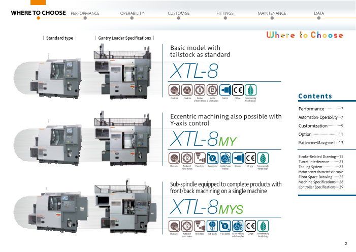
As the electrification of automobiles proceeds, demand for shaftwork Basic model with
components is increasing. The motor shafts fitted in electric vehicles are required tailstock as standard
to be light and also have excellent rotational balance, and for this reason they are
sometimes made of special high-durability materials. The XTL Series supports XTL-8
compound machining from deep hole boring to hard turning to side face milling
and eccentric machining, targeting shaftwork with a high level of difficulty such as
these motor shafts. TAKAMAZ also offers turnkey solutions for entire specialized 10
Chuck size Chuck size Number Number Tailstock CE type Environmentally Contents
production lines, which our competitors cannot provide. And we install functions of turret stations of turret stations friendly design
that lead to energy savings in various areas, which helps toward carbon neutrality. Performance ……………3
Eccentric machining also possible with Automation・Operability…7
Y-axis control
CNC PRECISION L ATHE XTL Customization …………9
SERIES XTL-8 Option……………………11
MY Maintenance・Management…13
Stroke-Related Drawing…15
Turret interference ………21
Chuck size Number of Power tools Y-axis control Spindle Cs-axis Tailstock CE type Environmentally
turret stations indexing friendly design Tooling System……………23
Motor power characteristic curve
Floor Space Drawing ……25
Sub-spindle equipped to complete products with Machine Specifications …28
Controller Specifications …29
front/back machining on a single machine
XTL-8MYS
Chuck size Number of Power tools Sub-spindle Y-axis control Cs-axis indexing Tailstock CE type Environmentally
turret stations on both spindles friendly design
1
Page3
WHERE TO CHOOSE PERFORMANCE OPERABILITY CUSTOMISE FITTINGS MAINTENANCE DATA
Leave Shaftwork to TAKAMAZ
| Standard type | | Gantry Loader Specifications |
As the electrification of automobiles proceeds, demand for shaftwork Basic model with
components is increasing. The motor shafts fitted in electric vehicles are required tailstock as standard
to be light and also have excellent rotational balance, and for this reason they are
sometimes made of special high-durability materials. The XTL Series supports XTL-8
compound machining from deep hole boring to hard turning to side face milling
and eccentric machining, targeting shaftwork with a high level of difficulty such as
these motor shafts. TAKAMAZ also offers turnkey solutions for entire specialized 10
Chuck size Chuck size Number Number Tailstock CE type Environmentally Contents
production lines, which our competitors cannot provide. And we install functions of turret stations of turret stations friendly design
that lead to energy savings in various areas, which helps toward carbon neutrality. Performance ……………3
Eccentric machining also possible with Automation・Operability…7
Y-axis control
CNC PRECISION L ATHE XTL Customization …………9
SERIES XTL-8 Option……………………11
MY Maintenance・Management…13
Stroke-Related Drawing…15
Turret interference ………21
Chuck size Number of Power tools Y-axis control Spindle Cs-axis Tailstock CE type Environmentally
turret stations indexing friendly design Tooling System……………23
Motor power characteristic curve
Floor Space Drawing ……25
Sub-spindle equipped to complete products with Machine Specifications …28
Controller Specifications …29
front/back machining on a single machine
XTL-8MYS
Chuck size Number of Power tools Sub-spindle Y-axis control Cs-axis indexing CE type Environmentally
turret stations on both spindles friendly design
2
Page4
WHERE TO CHOOSE PERFORMANCE OPERABILITY CUSTOMISE FITTINGS MAINTENANCE DATA PERFORMANCE
Balance between Toughness and Durability Essential Greatly Improved Production Efficiency
■ Focused on Shaft Work ■ Adoption of BMT Turret(XTL-8MY、XTL-8MYS) ■ Increased Spindle Torque (Compared to: XT-8)
The machine has a maximum turning length of 600 mm The bolt mounting system (BMT55) is used for the turret head, An AC15/11 kW motor, Spindle acceleration/deceleration time shortened * At 3,500min-1(XTL-8)
(XTL-8). A highly rigid square box-way slide construction improving the repeat positioning accuracy when mounting holders. which is one rank higher 【Non cutting time】Can be substantially reduced
for all axes is combined with a large-diameter φ100-mm The turret’s half-indexing mechanism allows up to 24 tools to be than before, is equipped
MOVIE
spindle to achieve stable machining accuracy and high mounted. A full lineup of attachments enables diverse tool layouts. as standard to improve Acceleration -27 Deceleration
cutting performance. The machine construction allows 2.2s(3.0s) % 1.8s(2.4s) -25%
machining performance
machining over the full Z-axis stroke even with special across the range. 3.00 3.00
high chuck specifications. -0.7s
-0.6s
2.00 2.00
BMT55 XTL-8 XTL-8
XT-8 XT-8
Maximum tool size: φ20 1.00 1.00
Acceleration Deceleration
sec sec
0 0
1,000 2,000 3,000 4,000 1,000 2,000 3,000 4,000
Spindle speed min-1 Spindle speed min-1
■ Tailstock (XTL-8、XTL-8MY) ■ Completion of Products Requiring Back Face Machining as a Second Process on a Single Machine(XTL-8MYS)
Holder for half-indexing The tailstock unit improves Providing a sub-spindle as standard makes it possible to complete products requiring back
the coaxiality, roundness face machining as a second process on a single machine. Completely synchronized rotation
and deflection of shaft of the two spindles also enables consistent high accuracy in shaft work machining.
workpieces. Square slideways
are adopted to achieve a Sub-spindle motor
AC7.5/5.5 kW motor installed
highly rigid structure.
■6-inch chuck
■Bearing inner diameter Φ75mm
■Max. bar diameter Φ35mm(Opt.)
■E axis (Cs) equipped as standard
3
TTiimmee
TTiimmee
Page5
WHERE TO CHOOSE PERFORMANCE OPERABILITY CUSTOMISE FITTINGS MAINTENANCE DATA PERFORMANCE
Balance between Toughness and Durability Essential Greatly Improved Production Efficiency
■ Focused on Shaft Work ■ Adoption of BMT Turret(XTL-8MY、XTL-8MYS) ■ Increased Spindle Torque (Compared to: XT-8)
The machine has a maximum turning length of 600 mm The bolt mounting system (BMT55) is used for the turret head, An AC15/11 kW motor, Spindle acceleration/deceleration time shortened * At 3,500min-1(XTL-8)
(XTL-8). A highly rigid square box-way slide construction improving the repeat positioning accuracy when mounting holders. which is one rank higher 【Non cutting time】Can be substantially reduced
for all axes is combined with a large-diameter φ100-mm The turret’s half-indexing mechanism allows up to 24 tools to be than before, is equipped
MOVIE
spindle to achieve stable machining accuracy and high mounted. A full lineup of attachments enables diverse tool layouts. as standard to improve Acceleration -27 Deceleration
cutting performance. The machine construction allows 2.2s(3.0s) % 1.8s(2.4s) -25%
machining performance
machining over the full Z-axis stroke even with special across the range. 3.00 3.00
high chuck specifications. -0.7s
-0.6s
2.00 2.00
BMT55 XTL-8 XTL-8
XT-8 XT-8
Maximum tool size: φ20 1.00 1.00
Acceleration Deceleration
sec sec
0 0
1,000 2,000 3,000 4,000 1,000 2,000 3,000 4,000
Spindle speed min-1 Spindle speed min-1
■ Tailstock (XTL-8、XTL-8MY) ■ Completion of Products Requiring Back Face Machining as a Second Process on a Single Machine(XTL-8MYS)
Holder for half-indexing The tailstock unit improves Providing a sub-spindle as standard makes it possible to complete products requiring back
the coaxiality, roundness face machining as a second process on a single machine. Completely synchronized rotation
and deflection of shaft of the two spindles also enables consistent high accuracy in shaft work machining.
workpieces. Square slideways
are adopted to achieve a Sub-spindle motor
AC7.5/5.5 kW motor installed
highly rigid structure.
■6-inch chuck
■Bearing inner diameter Φ75mm
■Max. bar diameter Φ35mm(Opt.)
■E axis (Cs) equipped as standard
4
Time
Time
Page6
WHERE TO CHOOSE PERFORMANCE OPERABILITY CUSTOMISE FITTINGS MAINTENANCE DATA PERFORMANCE
User Friendly Design Down to the Smallest Detail
Chuck Door 290mm
limit switch interlock switch
■ Designed with Attention to Detail ■ Safety Support ■ Visibility in the Machine
The coolant circuit is extended to prevent accumulation of A door interlock function is A safety window that is
chips and shorten the time spent cleaning the machine. In provided to completely isolate resistant to scratching
addition, the bed is constructed with flat sections eliminated the machining chamber, ensuring by chips and offers a
and slopes provided to make it hard for chips to build up. operator safety. high level of visibility is
※This machine conforms to safety adopted as standard.
A chuck clamping confirmation device is equipped as standards (JIS B 6031:2014), and
standard to prevent accuracy errors and the workpiece from the displayed machine parts are
equipped as standard.
flying out due to misclamping, so machining can be carried Hydraulic pressure Tailstock limit
switch Safety window switch
out safely. Faults of the hydraulic unit equipped with a chuck
pressure switch as standard are detected, eliminating danger.
Installed on the door lower cover Installed on the top part of the turret housing Capacity Note that accuracy is not guaranteed.
Depending on cutting conditions. XTL-8 XTL-8 XTL-8MYS
MY
Main-spindle Sub-spindle
■ Better Operability and ■ Tailstock slide simple movement unit
Maintainability (XTL-8,XTL-8MY) O.D. heavy cutting Cutting Cross Sectional Area(mm2) 1.89 1.87 1.85 0.85
The tailstock slide can be moved to
The machine construction (at continuous rating)
the required position by turning a
emphasizes accessibility, with handle in the socket at the rear of
a maintenance door provided the tailstock, which lightens the Groove width(mm) 5 5 5 5
behind the operation panel to workload in setup operations. O.D. grooving
facilitate maintenance of the
Distance from chuck jaw end(mm) 100 140 100 82
turret and tailstock.
Drill diameter(mm) φ32 φ32 φ32 φ23
Drilling
(at continuous rating)
Feedrate(mm/rev) f 0.14 f 0.16 f 0.13 f 0.20
※Workpiece:S45C
5
540mm
Page7
WHERE TO CHOOSE PERFORMANCE OPERABILITY CUSTOMISE FITTINGS MAINTENANCE DATA PERFORMANCE
User Friendly Design Down to the Smallest Detail
Chuck Door 290mm
limit switch interlock switch
■ Designed with Attention to Detail ■ Safety Support ■ Visibility in the Machine
The coolant circuit is extended to prevent accumulation of A door interlock function is A safety window that is
chips and shorten the time spent cleaning the machine. In provided to completely isolate resistant to scratching
addition, the bed is constructed with flat sections eliminated the machining chamber, ensuring by chips and offers a
and slopes provided to make it hard for chips to build up. operator safety. high level of visibility is
※This machine conforms to safety adopted as standard.
A chuck clamping confirmation device is equipped as standards (JIS B 6031:2014), and
standard to prevent accuracy errors and the workpiece from the displayed machine parts are
equipped as standard.
flying out due to misclamping, so machining can be carried Hydraulic pressure Tailstock limit
switch Safety window switch
out safely. Faults of the hydraulic unit equipped with a chuck
pressure switch as standard are detected, eliminating danger.
Installed on the door lower cover Installed on the top part of the turret housing Capacity Note that accuracy is not guaranteed.
Depending on cutting conditions. XTL-8 XTL-8 XTL-8MYS
MY
Main-spindle Sub-spindle
■ Better Operability and ■ Tailstock slide simple movement unit
Maintainability (XTL-8,XTL-8MY) O.D. heavy cutting Cutting Cross Sectional Area(mm2) 1.89 1.87 1.85 0.85
The tailstock slide can be moved to
The machine construction (at continuous rating)
the required position by turning a
emphasizes accessibility, with handle in the socket at the rear of
a maintenance door provided the tailstock, which lightens the Groove width(mm) 5 5 5 5
behind the operation panel to workload in setup operations. O.D. grooving
facilitate maintenance of the
Distance from chuck jaw end(mm) 100 140 100 82
turret and tailstock.
Drill diameter(mm) φ32 φ32 φ32 φ23
Drilling
(at continuous rating)
Feedrate(mm/rev) f 0.14 f 0.16 f 0.13 f 0.20
※Workpiece:S45C
6
540mm
Page8
WHERE TO CHOOSE PERFORMANCE OPERABILITY CUSTOMISE FITTINGS MAINTENANCE DATA OPERABILITY
Effects of Process Integration Building Labor-saving Systems
■ Versatile Gantry Loader ■「 Highly-productive Robot System」 ServoROT®series ■ Measuring and Cleaning
The loader type that is Along with growing needs for production automation, the variety of labor-saving TAKAMAZ provides systems that automate the whole sequence
handy for automating systems is also growing. The articulated robot in the photograph is characterized of workpiece transfer → measurement and inspection →
production lines is the by a high range of freedom, allowing unique production lines to be built. corrective machining → sorting good products. Among such
gantry loader. It also TAKAMAZ has a department that specializes in FA systems, where full-time automation equipment, our automated measuring devices have
has a wide range of system integrators propose labor-saving solutions, both new and remodelled. seen increasing demand year after year, and they allow users to
hand shapes and can FGH Loader maximize productivity and achieve the required machining
XTL-8 XTL-8MY XTL-8MYS XTL-8MYS
be operated in tandem Supply Machining Washing Drying Measurement Unloading
Item Unit Pendulum hand Hand for back face(OP) capabilities. The device itself is placed next to the lathe, and
with peripheral devices. Speed Traverse axis m/min 160 160 non-contact laser system and touch probe types are available for
Vertical axis selection according to the cost and required accuracy. The
Transferable Diameter mm φ75 φ150
workpiece dimensions Length mm 450 250 70 accumulated measurement data can also be utilized as necessary.
(reference values) Mass (one side) kg 5.0 1.5 ●Suppresses causes of non-uniformity
Pendulum hand(5kg) Hand for back face(1.5kg) ●Enables machining of 100% good products
●Allows automatic measurement + corrective machining within lines
●Allows high-efficiency, high-accuracy machining
■ Control System with Very Convenient Setup Operations ■ Operation System Integrating PC Functions and IT Technology ●Assures traceability of machining data
For better operability, control of the machine itself ■FANUC touch panel
and the loader can be centralized using FANUC and servo system used
Using one controller manufacturer
operations. And, in addition to the conventional improves maintainability.
operating functions, the optimal functions for ■Easy-to-understand loader
machine automation are equipped. Examples include setup, even for novices
a support function that allows the manual cutting The handle retrace function enables
F Loader operation screen confirmation of operations with a high
level of safety. TAKAMAZ OS Home screen
involved in tool offsetting to be done safely and Home screen for advance Traceability information MOVIE
notification of the causes on each workpiece stored
easily, and a handle retrace function that improves ■NC programs adopted of production stoppages in the unit
the efficiency of setup work. The traceability for loader operation
function helps with preventive maintenance by Standard G codes/M codes and
macros are used.
automatically saving operating statuses.
7
Page9
WHERE TO CHOOSE PERFORMANCE OPERABILITY CUSTOMISE FITTINGS MAINTENANCE DATA OPERABILITY
Effects of Process Integration Building Labor-saving Systems
■ Versatile Gantry Loader ■「 Highly-productive Robot System」 ServoROT®series ■ Measuring and Cleaning
The loader type that is Along with growing needs for production automation, the variety of labor-saving TAKAMAZ provides systems that automate the whole sequence
handy for automating systems is also growing. The articulated robot in the photograph is characterized of workpiece transfer → measurement and inspection →
production lines is the by a high range of freedom, allowing unique production lines to be built. corrective machining → sorting good products. Among such
gantry loader. It also TAKAMAZ has a department that specializes in FA systems, where full-time automation equipment, our automated measuring devices have
has a wide range of system integrators propose labor-saving solutions, both new and remodelled. seen increasing demand year after year, and they allow users to
hand shapes and can FGH Loader maximize productivity and achieve the required machining
XTL-8 XTL-8MY XTL-8MYS XTL-8MYS
be operated in tandem Supply Machining Washing Drying Measurement Unloading
Item Unit Pendulum hand Hand for back face(OP) capabilities. The device itself is placed next to the lathe, and
with peripheral devices. Speed Traverse axis m/min 160 160 non-contact laser system and touch probe types are available for
Vertical axis selection according to the cost and required accuracy. The
Transferable Diameter mm φ75 φ150
workpiece dimensions Length mm 450 250 70 accumulated measurement data can also be utilized as necessary.
(reference values) Mass (one side) kg 5.0 1.5 ●Suppresses causes of non-uniformity
Pendulum hand(5kg) Hand for back face(1.5kg) ●Enables machining of 100% good products
●Allows automatic measurement + corrective machining within lines
●Allows high-efficiency, high-accuracy machining
■ Control System with Very Convenient Setup Operations ■ Operation System Integrating PC Functions and IT Technology ●Assures traceability of machining data
For better operability, control of the machine itself ■FANUC touch panel
and the loader can be centralized using FANUC and servo system used
Using one controller manufacturer
operations. And, in addition to the conventional improves maintainability.
operating functions, the optimal functions for ■Easy-to-understand loader
machine automation are equipped. Examples include setup, even for novices
a support function that allows the manual cutting The handle retrace function enables
F Loader operation screen confirmation of operations with a high
level of safety. TAKAMAZ OS Home screen
involved in tool offsetting to be done safely and Home screen for advance Traceability information MOVIE
notification of the causes on each workpiece stored
easily, and a handle retrace function that improves ■NC programs adopted of production stoppages in the unit
the efficiency of setup work. The traceability for loader operation
function helps with preventive maintenance by Standard G codes/M codes and
macros are used.
automatically saving operating statuses.
8
Page10
WHERE TO CHOOSE PERFORMANCE OPERABILITY CUSTOMISE FITTINGS MAINTENANCE DATA CUSTOMISE
Providing Unique Products Tailored to Your Needs
■ Supply Devices ■ High-Pressure Coolant ■ Steady Rest ■ Mist Collector
Supply devices temporarily stock the workpiece material and Pressurized coolant is discharged When machining shaft work, sometimes This device collects oil mist generated by machining. It is an environmental
completed products. They realize labor savings by working in from high-pressure nozzles to a s e l f - c en t e r i ng s t e ady r e s t i s equipment that collects oil particles from the oil mist exhausted during
tandem with the loader. Various types are available to suit the forcibly expel chips in order to necessary. Coolant can be discharged machining and expels clean air.
workpiece shape and installation footprint. In addition, there are prevent damage to tools. from its nose to reduce the incidence The oil particles contained
also tray changers that can exchange entire trays, and conveyors It can also be expected to extend of rollers or workpieces becoming in oil mist is hamful to the
that operate in tandem with the previous and next processes. tool life. defective due to trapped chips, etc. human body, but adverse
effects on operator health
■Transfer conveyor ■Transfer shuttle can be prevented by
■Various stockers ■Parts feeder IN/OUT conveyor Tray changer
taking out the oil particles,
■Tray changer ■Turnover unit
■Positioning device and this also prevents
Rotary stocker effects on other production
equipment.
Example of use:
XY-120 PLUS + Mist collector
■ Bar Feeder(XTL-8MYS) ■ Parts catcher
(XTL-8MYS)
This equipment is for automatically supplying long pieces of bar stock.
By automatically feeding bar stock into the machine in tandem with the NC Unloads fully machined ■ Collet Chucks ■ Easy-lock Unit(Collet)
lathe, a large volume of products can be output in unmanned operation over a workpieces safely outside
long time with no need to stop machining, making it possible to greatly improve the machine. TAKAMAZ also manufactures collet chucks. We do this in a This unit shortens work time by changing your screw-in collets NEW
plant specialized for that purpose, using machining methods to the quick-change specification. Fitting an intermediate
production efficiency in the plant. honed over many years, and undertaking everything from flange, and combination joints on the sleeve side and collet
machining to heat treatment and grinding. TAKAMAZ collet side, completes the change to a simple one-touch change
chucks boasting robust spring characteristics, wear specification. Customers can continue to use the collets and
resistance and high accuracy are able to MOVIE flanges that they already have. Setting joints on MOVIE
grip all kinds of workpieces. TAKAMAZ also multiple collets in advance makes collet changes
manufactures special orders according to more efficient and renders troublesome stroke
Example of use: XT-8 + bar feeder your requirements. adjustments unnecessary.
In addition, a full range of options are available. For details, ask our sales personnel.
9
Page11
WHERE TO CHOOSE PERFORMANCE OPERABILITY CUSTOMISE FITTINGS MAINTENANCE DATA CUSTOMISE
Providing Unique Products Tailored to Your Needs
■ Supply Devices ■ High-Pressure Coolant ■ Steady Rest ■ Mist Collector
Supply devices temporarily stock the workpiece material and Pressurized coolant is discharged When machining shaft work, sometimes This device collects oil mist generated by machining. It is an environmental
completed products. They realize labor savings by working in from high-pressure nozzles to a s e l f - c en t e r i ng s t e ady r e s t i s equipment that collects oil particles from the oil mist exhausted during
tandem with the loader. Various types are available to suit the forcibly expel chips in order to necessary. Coolant can be discharged machining and expels clean air.
workpiece shape and installation footprint. In addition, there are prevent damage to tools. from its nose to reduce the incidence The oil particles contained
also tray changers that can exchange entire trays, and conveyors It can also be expected to extend of rollers or workpieces becoming in oil mist is hamful to the
that operate in tandem with the previous and next processes. tool life. defective due to trapped chips, etc. human body, but adverse
effects on operator health
■Transfer conveyor ■Transfer shuttle can be prevented by
■Various stockers ■Parts feeder IN/OUT conveyor Tray changer
taking out the oil particles,
■Tray changer ■Turnover unit
■Positioning device and this also prevents
Rotary stocker effects on other production
equipment.
Example of use:
XY-120 PLUS + Mist collector
■ Bar Feeder(XTL-8MYS) ■ Parts catcher
(XTL-8MYS)
This equipment is for automatically supplying long pieces of bar stock.
By automatically feeding bar stock into the machine in tandem with the NC Unloads fully machined ■ Collet Chucks ■ Easy-lock Unit(Collet)
lathe, a large volume of products can be output in unmanned operation over a workpieces safely outside
long time with no need to stop machining, making it possible to greatly improve the machine. TAKAMAZ also manufactures collet chucks. We do this in a This unit shortens work time by changing your screw-in collets NEW
plant specialized for that purpose, using machining methods to the quick-change specification. Fitting an intermediate
production efficiency in the plant. honed over many years, and undertaking everything from flange, and combination joints on the sleeve side and collet
machining to heat treatment and grinding. TAKAMAZ collet side, completes the change to a simple one-touch change
chucks boasting robust spring characteristics, wear specification. Customers can continue to use the collets and
resistance and high accuracy are able to MOVIE flanges that they already have. Setting joints on MOVIE
grip all kinds of workpieces. TAKAMAZ also multiple collets in advance makes collet changes
manufactures special orders according to more efficient and renders troublesome stroke
Example of use: XT-8 + bar feeder your requirements. adjustments unnecessary.
In addition, a full range of options are available. For details, ask our sales personnel.
10
Page12
WHERE TO CHOOSE PERFORMANCE OPERABILITY CUSTOMISE FITTINGS MAINTENANCE DATA FITTINGS
Chip Processing can be Matched to the Application T-ECO Support Environmental Considerations as Standard Specifications
Spindle Acceleration/Deceleration Time Fully Adjustable Power Consumption Monitor
■ Chip Conveyor The spindle acceleration/deceleration time can be adjusted as required to switch between Energy usage can be managed at all times, including the power on time,
A variety of chip shapes are generated depending on the cutting conditions and workpiece operation that prioritizes cutting time and operation that prioritizes energy savings. production quantity, energy consumption, average power consumption per
material. If they are left they accumulate inside the machine, they can obstruct machining or get workpiece, and energy saving effect.
Acceleration/Deceleration Time Adjustable as Required
inside the machine, and in the worst case this can lead to the machine being stopped by a fault. A Example with spindle acceleration/deceleration set at 80%: This helps to reduce the environmental load and manage running costs.
chip conveyor can prevent and eliminate such problems. We offer a lineup of chip conveyor
models matched to a variety of machines. Please select the equipment that suits your application. Power -2% Cycle time +1%
consumption
* According to actual values measured * According to actual values measured
Steel : Curly, long Castings : Chip-shaped Aluminum : Chip-shaped by TAKAMAZ by TAKAMAZ
「Actual figure for XTL-8MY」 「Actual figure for XTL-8,XTL-8MY」
* In lines comprising multiple machines in sequence, when there are
Spiral Type Floor Type waiting times for material loading due to differences in process cycle
times, operation that prioritizes energy savings can be used effectively
to achieve power savings without increasing the line cycle time.
Steel : Curly, long Steel : Granular Aluminum : Curly, long Equipment
Compatibility Table Magnet i c Non-magnet i c
Steel Castings Aluminum Brass 20% Reduction in Power Consumption while Machine is Stopped When hydraulic
○:Can be used pump is OFF
An “idle stop function” that automatically stops power supply to the hydraulic pump
×:Cannot be used when the machine is stopped is now incorporated. This provides a power conservation Power consumption-25% Production information Power consumption
effect when the machine is stopped, such as during machine setup work. (per-day basis) history
Steel : Curly, short Brass : Needle-shaped Aluminum : Granular * According to actual values measured by TAKAMAZ
「Actual figure for XTL-8」
Type
Spiral ○ ○ × × × × × × × × × × × ■ Chuck Stroke Check Function
Floor ○ ○ ○ × × × × × × × × × × Just set the clamping and unclamping positions, with no need 【Previously:Chuck clamp detector】 【Chuck stroke check function】
Scraper × ○ ○ ○ ○ ○ × ○ ○ ○ ○ ○ ○
Steel : Curly, short Brass : Granular Aluminum : Curly, long to change the position of the proximity sensor as previously.
Magnet scraper × ○ ○ ○ ○ ○ × × × × × × × Proximity sensor Position sensor
Drum filter scraper × × × × × × × ○ ○ ○ ○ ○ ○ ■No need to change the sensor position using tools ●2 Proximity sensor used ●1 position sensor used
2-stage(drum + floor) × × × × × × ○ ○ ○ ○ ○ ○ ○ ■Register clamp and unclamp positions on the Chuck ●Sensor adjustment using tools
●Needed to remove the machine Chuck ●No tools required for sensor adjustment
dedicated screen (stroke numbers: max. 32 pairs) ●Sensor detection position can be set on
Magnet roller × ○ ○ ○ ○ ○ × × × × × × × cover and change the sensor a dedicated screen without removing the
■Registered stroke numbers can be called by selection Chucking cylinder position at setup changes Chucking cylinder machine cover
on the screen or by calling them in a program.
11
Needle-shaped Granular
Chip-shaped
Curly, short
Needle-shaped Granular
Chip-shaped
Curly, short
Curly, long
Needle-shaped Granular
Chip-shaped
Needle-shaped Granular
Chip-shaped
Curly, short
Curly, long
Page13
WHERE TO CHOOSE PERFORMANCE OPERABILITY CUSTOMISE FITTINGS MAINTENANCE DATA FITTINGS
Chip Processing can be Matched to the Application T-ECO Support Environmental Considerations as Standard Specifications
Spindle Acceleration/Deceleration Time Fully Adjustable Power Consumption Monitor
■ Chip Conveyor The spindle acceleration/deceleration time can be adjusted as required to switch between Energy usage can be managed at all times, including the power on time,
A variety of chip shapes are generated depending on the cutting conditions and workpiece operation that prioritizes cutting time and operation that prioritizes energy savings. production quantity, energy consumption, average power consumption per
material. If they are left they accumulate inside the machine, they can obstruct machining or get workpiece, and energy saving effect.
Acceleration/Deceleration Time Adjustable as Required
inside the machine, and in the worst case this can lead to the machine being stopped by a fault. A Example with spindle acceleration/deceleration set at 80%: This helps to reduce the environmental load and manage running costs.
chip conveyor can prevent and eliminate such problems. We offer a lineup of chip conveyor
models matched to a variety of machines. Please select the equipment that suits your application. Power -2% Cycle time +1%
consumption
* According to actual values measured * According to actual values measured
Steel : Curly, long Castings : Chip-shaped Aluminum : Chip-shaped by TAKAMAZ by TAKAMAZ
「Actual figure for XTL-8MY」 「Actual figure for XTL-8,XTL-8MY」
* In lines comprising multiple machines in sequence, when there are
Spiral Type Floor Type waiting times for material loading due to differences in process cycle
times, operation that prioritizes energy savings can be used effectively
to achieve power savings without increasing the line cycle time.
Steel : Curly, long Steel : Granular Aluminum : Curly, long Equipment
Compatibility Table Magnet i c Non-magnet i c
Steel Castings Aluminum Brass 20% Reduction in Power Consumption while Machine is Stopped When hydraulic
○:Can be used pump is OFF
An “idle stop function” that automatically stops power supply to the hydraulic pump
×:Cannot be used when the machine is stopped is now incorporated. This provides a power conservation Power consumption-25% Production information Power consumption
effect when the machine is stopped, such as during machine setup work. (per-day basis) history
Steel : Curly, short Brass : Needle-shaped Aluminum : Granular * According to actual values measured by TAKAMAZ
「Actual figure for XTL-8」
Type
Spiral ○ ○ × × × × × × × × × × × ■ Chuck Stroke Check Function
Floor ○ ○ ○ × × × × × × × × × × Just set the clamping and unclamping positions, with no need 【Previously:Chuck clamp detector】 【Chuck stroke check function】
Scraper × ○ ○ ○ ○ ○ × ○ ○ ○ ○ ○ ○
Steel : Curly, short Brass : Granular Aluminum : Curly, long to change the position of the proximity sensor as previously.
Magnet scraper × ○ ○ ○ ○ ○ × × × × × × × Proximity sensor Position sensor
Drum filter scraper × × × × × × × ○ ○ ○ ○ ○ ○ ■No need to change the sensor position using tools ●2 Proximity sensor used ●1 position sensor used
2-stage(drum + floor) × × × × × × ○ ○ ○ ○ ○ ○ ○ ■Register clamp and unclamp positions on the Chuck ●Sensor adjustment using tools
●Needed to remove the machine Chuck ●No tools required for sensor adjustment
dedicated screen (stroke numbers: max. 32 pairs) ●Sensor detection position can be set on
Magnet roller × ○ ○ ○ ○ ○ × × × × × × × cover and change the sensor a dedicated screen without removing the
■Registered stroke numbers can be called by selection Chucking cylinder position at setup changes Chucking cylinder machine cover
on the screen or by calling them in a program.
12
Needle-shaped Granular
Chip-shaped
Curly, short
Needle-shaped Granular
Chip-shaped
Curly, short
Curly, long
Needle-shaped Granular
Chip-shaped
Needle-shaped Granular
Chip-shaped
Curly, short
Curly, long
Page14
WHERE TO CHOOSE PERFORMANCE OPERABILITY CUSTOMISE FITTINGS MAINTENANCE DATA MAINTENANCE
Original Systems Designed to Improve Productivity
®
®
Thermony Issues Affecting the Machine Tool Industry Advantages of Providing T-PROGRAM GUIDE
Temperature Measured values Prediction of Offset values
The machined dimension values change as the machine temperature changes due to the measurement input to CNC thermal displacement input to CNC
user's conditions of use(machining conditions) and the environmental conditions(factory Production costs increasing due to rising raw
Increased costs Ability to assess the process and check conditions at a glance Easy to reflect machining results (shape correction)
temperature, etc.). material, energy and personnel costs Tool numbers, cutting speeds, Recalculation of coordinates unnecessary, with quick and
This system predicts the amount of thermal displacement based on the temperature changes CNC etc., for each process displayed in a list simple correction through screen operations alone
at various sections of the machine and provides compensation values to the CNC controller in controller
Difficult to maintain quality and pass on skills
order to minimize affects on the machining dimension values. When Thermony is not applied, Insufficient manpower due to shortage of skilled technicians
the amount of change in the machined diameter over 8 hours is 15 μm, but when it is applied Temperature input unit
the amount of change is suppressed to 6 μm, exhibiting an improvement of 60%.
Feedback Calculation program to predict the individual Young people are not coming into the
Ambient temperature: Temperature rise of 5°C over 3 hours starting at 9:00 amount of thermal displacement Insufficient successors machine tool field, and the skills and
: Rapid change in temperature by 3°C over a short time Prediction of amount of thermal displacement in real time knowledge are not being passed on.
20 10 min.stopped 60 min. stopped 20 min. stopped 数値変更による修正 形状変更による修正
18 Thermony applied Position command Automatic input of compensation in each cycle
16
14 Thermony not applied The first requirement when mass producing parts using machine
12 Easy to reflect machining results (cutting condition correction) Ability to check using simulations
10
8 tools is setup. A lot of preparation is required, from understanding
6 Quick editing in the process list, with Check interference and the cut profile simply
4 the shape of the material and creating a cutting program, to
2 no need to search for the targeted block with animations and tool path displays.
0 selecting and mounting the cutting tool and chuck. Unlike skilled
-2
-4 workers, it takes time for inexperienced operators to master the
-6
-8 know-how required for creating programs for cutting to the required
-10
Time 9:00 10:00 11:00 12:00 13:00 14:00 15:00 16:00 17:00 accuracy in a short period of time, making full use of G-codes and so
Thermony not applied - Amount of change = 15 μm on. They will also be apprehensive about their ability to accomplisah
Thermony applied - Amount of change = 6 μm(improved by 60%) the cutting using the completed program without any interference.
To help under these conditions we have an assistance function that
enables even operators with little experience to create programs
without errors, called the T-PROGRAM GUIDE.
13
Change of diameterμm
Page15
WHERE TO CHOOSE PERFORMANCE OPERABILITY CUSTOMISE FITTINGS MAINTENANCE DATA MAINTENANCE
Original Systems Designed to Improve Productivity
®
®
Thermony Issues Affecting the Machine Tool Industry Advantages of Providing T-PROGRAM GUIDE
Temperature Measured values Prediction of Offset values
The machined dimension values change as the machine temperature changes due to the measurement input to CNC thermal displacement input to CNC
user's conditions of use(machining conditions) and the environmental conditions(factory Production costs increasing due to rising raw
Increased costs Ability to assess the process and check conditions at a glance Easy to reflect machining results (shape correction)
temperature, etc.). material, energy and personnel costs Tool numbers, cutting speeds, Recalculation of coordinates unnecessary, with quick and
This system predicts the amount of thermal displacement based on the temperature changes CNC etc., for each process displayed in a list simple correction through screen operations alone
at various sections of the machine and provides compensation values to the CNC controller in controller
Difficult to maintain quality and pass on skills
order to minimize affects on the machining dimension values. When Thermony is not applied, Insufficient manpower due to shortage of skilled technicians
the amount of change in the machined diameter over 8 hours is 15 μm, but when it is applied Temperature input unit
the amount of change is suppressed to 6 μm, exhibiting an improvement of 60%.
Feedback Calculation program to predict the individual Young people are not coming into the
Ambient temperature: Temperature rise of 5°C over 3 hours starting at 9:00 amount of thermal displacement Insufficient successors machine tool field, and the skills and
: Rapid change in temperature by 3°C over a short time Prediction of amount of thermal displacement in real time knowledge are not being passed on.
20 10 min.stopped 60 min. stopped 20 min. stopped 数値変更による修正 形状変更による修正
18 Thermony applied Position command Automatic input of compensation in each cycle
16
14 Thermony not applied The first requirement when mass producing parts using machine
12 Easy to reflect machining results (cutting condition correction) Ability to check using simulations
10
8 tools is setup. A lot of preparation is required, from understanding
6 Quick editing in the process list, with Check interference and the cut profile simply
4 the shape of the material and creating a cutting program, to
2 no need to search for the targeted block with animations and tool path displays.
0 selecting and mounting the cutting tool and chuck. Unlike skilled
-2
-4 workers, it takes time for inexperienced operators to master the
-6
-8 know-how required for creating programs for cutting to the required
-10
Time 9:00 10:00 11:00 12:00 13:00 14:00 15:00 16:00 17:00 accuracy in a short period of time, making full use of G-codes and so
Thermony not applied - Amount of change = 15 μm on. They will also be apprehensive about their ability to accomplisah
Thermony applied - Amount of change = 6 μm(improved by 60%) the cutting using the completed program without any interference.
To help under these conditions we have an assistance function that
enables even operators with little experience to create programs
without errors, called the T-PROGRAM GUIDE.
14
Change of diameterμm
Page16
WHERE TO CHOOSE PERFORMANCE OPERABILITY CUSTOMISE FITTINGS MAINTENANCE DATA DATA
Stroke-Related Drawing XTL-8 XTL-8
Standard φ100 spindle/standard 8-station turret Standard φ100 spindle・OP12-station turret
Front shift specification Rear shift (Option) Front shift specification Rear shift (Option)
850 950
850 950 750 85 15 850 85 15
745 90 15 845 90 15
138 600st. 7 238 600st. 7
47 98 593 47 98 693
143 600st. 7 243 600st. 7
47 98 598 47 98 698
FUTAMURA FUTAMURA
TSD-D43 type NCF4-002
(2 Acollet) MT-4 TSD-D43 type NCF4-002 FUTAMURA FUTAMURA
(2 Acollet) MT-4
TSD-D43 type NCF4-002
(2 Acollet) MT-4 TSD-D43 type NCF4-002
(2 Acollet) MT-4
8-inch 545 8-inch 645
ZA6-8 ZA6-8 8-inch 8-inch
ZA6-8 545 ZA6-8 645
47 146 100st. 240st. 108 47 146 100st. 240st. 108
Tailstock spindle Tailstock slide Tailstock spindle Tailstock slide 47 146 100st. 240st. 108 47 146 100st. 240st. 108
stroke stroke stroke stroke Tailstock spindle Tailstock slide Tailstock spindle Tailstock slide
847 947 stroke stroke stroke stroke
847 947
850 950
850 950 750 85 15 850 85 15
745 90 15 845 90 15
96 600st. 45 4 196 600st. 45 4
47 98 551 47 98 651 101 600st. 45 4 201 600st. 45 4
47 98 556 47 98 656
TSD-D43 type FUTAMURA
NCF4-002 TSD-D43 type FUTAMURA
(2 Acollet) MT-4 (2 Acollet) NCF4-002 TSD-D43 type FUTAMURA FUTAMURA
MT-4 (2 Acollet) NCF4-002 TSD-D43 type
(2 Acollet) NCF4-002
MT-4 MT-4
8-inch 503 8-inch 603
ZA6-8 ZA6-8 8-inch 8-inch
ZA6-8 508 ZA6-8 608
47 146 100st. 240st. 108 47 146 100st. 240st. 108
Tailstock spindle Tailstock slide Tailstock spindle Tailstock slide 47 146 100st. 240st. 108 47 146 100st. 240st. 108
stroke stroke stroke stroke Tailstock spindle Tailstock slide Tailstock spindle Tailstock slide
847 947 stroke stroke stroke stroke
847 947
Unit(mm)
15
160 40 150
177 (13) 190st. 30 150
190st. 170
φ75 φ75
350 350
160 40 150
177 (13) 190st. 30 150
190st. 170
φ75 φ75
350 350
140 40 210
177 (13) 190st. 30 210
190st. 150
φ75 φ75
390 390
140 40 210
177 (13) 190st. 30 210
190st. 150
φ75 φ75
390 390
Page17
WHERE TO CHOOSE PERFORMANCE OPERABILITY CUSTOMISE FITTINGS MAINTENANCE DATA DATA
Stroke-Related Drawing XTL-8 XTL-8
Standard φ100 spindle/standard 8-station turret Standard φ100 spindle・OP12-station turret
Front shift specification Rear shift (Option) Front shift specification Rear shift (Option)
850 950
850 950 750 85 15 850 85 15
745 90 15 845 90 15
138 600st. 7 238 600st. 7
47 98 593 47 98 693
143 600st. 7 243 600st. 7
47 98 598 47 98 698
FUTAMURA FUTAMURA
TSD-D43 type NCF4-002
(2 Acollet) MT-4 TSD-D43 type NCF4-002 FUTAMURA FUTAMURA
(2 Acollet) MT-4
TSD-D43 type NCF4-002
(2 Acollet) MT-4 TSD-D43 type NCF4-002
(2 Acollet) MT-4
8-inch 545 8-inch 645
ZA6-8 ZA6-8 8-inch 8-inch
ZA6-8 545 ZA6-8 645
47 146 100st. 240st. 108 47 146 100st. 240st. 108
Tailstock spindle Tailstock slide Tailstock spindle Tailstock slide 47 146 100st. 240st. 108 47 146 100st. 240st. 108
stroke stroke stroke stroke Tailstock spindle Tailstock slide Tailstock spindle Tailstock slide
847 947 stroke stroke stroke stroke
847 947
850 950
850 950 750 85 15 850 85 15
745 90 15 845 90 15
96 600st. 45 4 196 600st. 45 4
47 98 551 47 98 651 101 600st. 45 4 201 600st. 45 4
47 98 556 47 98 656
TSD-D43 type FUTAMURA
NCF4-002 TSD-D43 type FUTAMURA
(2 Acollet) MT-4 (2 Acollet) NCF4-002 TSD-D43 type FUTAMURA FUTAMURA
MT-4 (2 Acollet) NCF4-002 TSD-D43 type
(2 Acollet) NCF4-002
MT-4 MT-4
8-inch 503 8-inch 603
ZA6-8 ZA6-8 8-inch 8-inch
ZA6-8 508 ZA6-8 608
47 146 100st. 240st. 108 47 146 100st. 240st. 108
Tailstock spindle Tailstock slide Tailstock spindle Tailstock slide 47 146 100st. 240st. 108 47 146 100st. 240st. 108
stroke stroke stroke stroke Tailstock spindle Tailstock slide Tailstock spindle Tailstock slide
847 947 stroke stroke stroke stroke
847 947
Unit(mm)
16
160 40 150
177 (13) 190st. 30 150
190st. 170
φ75 φ75
350 350
160 40 150
177 (13) 190st. 30 150
190st. 170
φ75 φ75
350 350
140 40 210
177 (13) 190st. 30 210
190st. 150
φ75 φ75
390 390
140 40 210
177 (13) 190st. 30 210
190st. 150
φ75 φ75
390 390
Page18
WHERE TO CHOOSE PERFORMANCE OPERABILITY CUSTOMISE FITTINGS MAINTENANCE DATA DATA
Stroke-Related Drawing XTL-8 XTL-8MY
OPφ120 Spindle・Standard 8-station turret/OP12-station turret Standard φ100 Spindle・12-station turre(t BMT55)
8-station turret 12-station turret (Option) Front shift Rear shift (Option)
946 850 950
846 85 15
946 685 90 65 10 785 90 65 10
841 90 15 20 45 20 45
234 600st. 7 32 32
60 184 590 239 600st. 7 □25 □25
60 184 595
47 98 508 47 98 608
103 550st. 7 203 550st. 7
FUTAMURA FUTAMURA
10-inch NCF4-002
MT-4 10-inch NCF4-002
BR10 BR10 MT-4 FUTAMURA FUTAMURA
TSC-D43 type NCF4-002 TSC-D43 type NCF4-002
(2 Acollet) MT-4 (2 Acollet) MT-4
8-inch 460 8-inch 560
ZA6-8 ZA6-8
100st. 240st. 108 100st. 240st. 108 47 146 100st. 240st. 108 47 146 100st. 240st. 108
Tailstock spindle Tailstock slide Tailstock spindle Tailstock slide Tailstock spindle Tailstock slide Tailstock spindle Tailstock slide
stroke stroke stroke stroke
943 943 847 stroke stroke 947 stroke stroke
946
846 85 15 850 950
946 685 90 65 10 785 90 65 10
841 90 15 20 45 20 45
192 600st. 45 4
60 184 548 197 600st. 45 4
60 184 553 80 550st. 45 10 180 550st. 45 10
47 98 485 47 98 585
10-inch FUTAMURA
NCF4-002 10-inch FUTAMURA
BR10 BR10 NCF4-002 FUTAMURA FUTAMURA
MT-4 MT-4 TSC-D43 type NCF4-002 TSC-D43 type NCF4-002
(2 Acollet) MT-4 (2 Acollet) MT-4
8-inch 437 8-inch 537
ZA6-8 ZA6-8
100st. 240st. 108 100st. 240st. 108
Tailstock spindle Tailstock slide Tailstock spindle Tailstock slide 47 146 100st. 240st. 108 47 146 100st. 240st. 108
stroke stroke stroke stroke Tailstock spindle Tailstock slide Tailstock spindle Tailstock slide
943 943 847 stroke stroke 947 stroke stroke
Unit(mm)
17
160 40 150
177 (13) 190st. 30 150
190st. 170
φ75 φ75
350 350
140 40 210
177 (13) 190st. 30 210
190st. 150
φ75 φ75
390 390
150 60 190 31 64 190
(162) (13) 115 55
175st. 175st.
φ75 φ75
400 400
150 60 190 31 64 190
(162) (13) 115 55
175st. 175st.
φ75 φ75
400 400
Page19
WHERE TO CHOOSE PERFORMANCE OPERABILITY CUSTOMISE FITTINGS MAINTENANCE DATA DATA
Stroke-Related Drawing XTL-8 XTL-8MY
OPφ120 Spindle・Standard 8-station turret/OP12-station turret Standard φ100 Spindle・12-station turre(t BMT55)
8-station turret 12-station turret (Option) Front shift Rear shift (Option)
946 850 950
846 85 15
946 685 90 65 10 785 90 65 10
841 90 15 20 45 20 45
234 600st. 7 32 32
60 184 590 239 600st. 7 □25 □25
60 184 595
47 98 508 47 98 608
103 550st. 7 203 550st. 7
FUTAMURA FUTAMURA
10-inch NCF4-002
MT-4 10-inch NCF4-002
BR10 BR10 MT-4 FUTAMURA FUTAMURA
TSC-D43 type NCF4-002 TSC-D43 type NCF4-002
(2 Acollet) MT-4 (2 Acollet) MT-4
8-inch 460 8-inch 560
ZA6-8 ZA6-8
100st. 240st. 108 100st. 240st. 108 47 146 100st. 240st. 108 47 146 100st. 240st. 108
Tailstock spindle Tailstock slide Tailstock spindle Tailstock slide Tailstock spindle Tailstock slide Tailstock spindle Tailstock slide
stroke stroke stroke stroke
943 943 847 stroke stroke 947 stroke stroke
946
846 85 15 850 950
946 685 90 65 10 785 90 65 10
841 90 15 20 45 20 45
192 600st. 45 4
60 184 548 197 600st. 45 4
60 184 553 80 550st. 45 10 180 550st. 45 10
47 98 485 47 98 585
10-inch FUTAMURA
NCF4-002 10-inch FUTAMURA
BR10 BR10 NCF4-002 FUTAMURA FUTAMURA
MT-4 MT-4 TSC-D43 type NCF4-002 TSC-D43 type NCF4-002
(2 Acollet) MT-4 (2 Acollet) MT-4
8-inch 437 8-inch 537
ZA6-8 ZA6-8
100st. 240st. 108 100st. 240st. 108
Tailstock spindle Tailstock slide Tailstock spindle Tailstock slide 47 146 100st. 240st. 108 47 146 100st. 240st. 108
stroke stroke stroke stroke Tailstock spindle Tailstock slide Tailstock spindle Tailstock slide
943 943 847 stroke stroke 947 stroke stroke
Unit(mm)
18
160 40 150
177 (13) 190st. 30 150
190st. 170
φ75 φ75
350 350
140 40 210
177 (13) 190st. 30 210
190st. 150
φ75 φ75
390 390
150 60 190 31 64 190
(162) (13) 115 55
175st. 175st.
φ75 φ75
400 400
150 60 190 31 64 190
(162) (13) 115 55
175st. 175st.
φ75 φ75
400 400
Page20
WHERE TO CHOOSE PERFORMANCE OPERABILITY CUSTOMISE FITTINGS MAINTENANCE DATA DATA
Stroke-Related Drawing XTL-8MY XTL-8MYS
Milling range・12-station turre(t BMT55) 12-station turre(t BMT55)
Side milling・Front shift Side milling・Rear shift (Option) Front shift
850 950 O.D. holder Side milling Cut-off holder
685 90 65 10 785 90 65 10 460 460 460
20 45 20 45 (280) 125 55 55 MAX.125 (280) 80 100 100 MAX.80 (334) 51 75 75 51
104
77 77 167
90 90 90
75
180 550st. 280 550st.
47 98 585 47 98 685 (33) Z:350st Z:200st (110) Z:350st Z:200st (35) Z:350st Z:200st
(4.6) (4.6) (4.6)
47 152.2 A:400st 129.2 47 47 152.2 A:400st 129.2 47 47 152.2 A:400st 129.2 47
FUTAMURA FUTAMURA
NCF4-002 NCF4-002 Home 2nd position 2nd position Home position 2nd position
TSC-D43 type φ20 MT-4 TSC-D43 type φ20 MT-4 Kitagawa position Kitagawa Kitagawa Home Kitagawa Kitagawa Kitagawa
(2Acollet) (2Acollet) BR08 BR06 BR08 position BR06 BR08 BR06
8-inch 6-inch 8-inch 6-inch 8-inch 6-inch
Takamaz collet Takamaz collet Takamaz collet
537 687 TPC3-CS55 TPC3-CS43 φ20 Takamaz collet Takamaz collet Takamaz collet
8-inch 8-inch TPC3-CS55 TPC3-CS43 TPC3-CS55 TPC3-CS43
ZA6-8 ZA6-8
47 146 100st. 240st. 108 47 146 100st. 240st. 108
Tailstock spindle Tailstock slide Tailstock spindle Tailstock slide 47 175 (366) 145 47 47 175 (366) 145 47 47 175 (366) 145 47
780 780
847 stroke stroke 780
947 stroke stroke
Face milling・Front shift Face milling・Rear shift (Option) Rear shift (Option)
850 950 O.D. holder Side milling Cut-off holder
685 90 65 10 785 90 65 10 560 560 560
555 75 55 555 175 55
5 550st. (MAX) 5 550st. (MAX) (380) 125 55 55 MAX.125 (380) 80 100 100 MAX.80 (434) 51 75 75 51
104
77 77
167
90 90 90
80 550st. 180 550st.
47 98 485 47 98 585 75
(133) Z:350st Z:200st (210) Z:350st Z:200st (135) Z:350st Z:200st
47 152.2 (104.6) A:400st 129.2 47 47 152.2 (104.6) A:400st 129.2 47 47 152.2 (104.6) A:400st 129.2 47
FUTAMURA FUTAMURA Home position 2nd position
Home 2nd position 2nd position
TSC-D43 type NCF4-002
(2Acollet) MT-4 TSC-D43 type NCF4-002 Kitagawa position Kitagawa Kitagawa Home Kitagawa Kitagawa Kitagawa
(2Acollet) MT-4 BR08 BR06 BR08 position BR06 BR08 BR06
8-inch 6-inch 8-inch 6-inch 8-inch 6-inch
Takamaz collet Takamaz collet
TPC3-CS55 TPC3-CS43 φ20 Takamaz collet Takamaz collet Takamaz collet
8-inch 437 8-inch 537 Takamaz collet TPC3-CS43 TPC3-CS55 TPC3-CS43
ZA6-8 ZA6-8 TPC3-CS55
47 146 100st. 240st. 108 47 146 100st. 240st. 108
Tailstock spindle Tailstock slide Tailstock spindle Tailstock slide 47 175 66 (400) 145 47 47 175 (66) A:400st 145 47 47 175 (66) A:400st 145 47
847 stroke stroke 947 stroke stroke 880 880 880
Unit(mm)
19
175st. 60 190 175st. 70 190
150 140
60
(MAX)
φ75 φ75
400 400
175st. 60 190
150
175st. 70 190
140
60
(MAX)
φ75 φ75
400 400
X:175st X:175st
(115) 95 190 (115) 95 190
400 400
φ20 φ20
MAX.50 MAX.50
X:175st X:175st
(90) 120 190 (90) 120 190
400 400
X:175st X:175st
(90) 120 190 (90) 120 190
400 400