


TAKAMAZ XY Series Catalog
Product Catalog
CNC Multi turning center
Document Information
| Document Title | TAKAMAZ XY Series Catalog |
|---|---|
| Document Type | Product Catalog |
| File size | 4.1Mb |
| Category | |
| Company | TAKAMAZ (TAKAMATSU MACHINERY Co.,ltd) (Documents List) |
Documents related to this company


Document Contents
Page1
CNC Multi-Turning Center
XYseries
TAKAMATSU MACHINERY CO., LTD. TAKAMAZ MACHINERY MEXICO, S.A.DE C.V.
■HEAD OFFICE & PLANT AVENIDA DE LOS INDUSTRIALES 522, LOCAL 4, INDUSTRIAL JULIAN DE OBREGON, 37290 LEON,
1-8 ASAHIGAOKA HAKUSAN-CITY ISHIKAWA JAPAN. 924-8558 TEL +81-(0)76-207-6155 FAX +81-(0)76-274-1418 GUANAJUATO MEXICO
■ASAHI PLANT TEL +52-477-784-0468
4-13 ASAHIGAOKA HAKUSAN-CITY ISHIKAWA JAPAN. 924-0004 TEL +81-(0)76-274-0123 FAX +81-(0)76-274-8530 TAKAMATSU MACHINERY VIETNAM CO., LTD
TAKAMATSU MACHINERY U.S.A., INC. NO.76 M HOANG QUOC VIET, PHU MY WARD, DISTRICT 7, HO CHI MINH CITY, VIETNAM
■CHICAGO HEAD OFFICE TEL +84-(0)28-3620-5671 FAX +84-(0)28-3620-5673
1280 LANDMEIER ROAD ELK GROVE VILLAGE, IL 60007 USA TEL +1-(0)847-981-8577 FAX +1-(0)847-981-8599
TAKAMAZ MACHINERY EUROPE GmbH
IM HÜLSENFELD 19, 40721 HILDEN, GERMANY TEL +49-(0)2103-789-4882 FAX +49-(0)2103-789-4883
TAKAMAZ MACHINERY( HANGZHOU) CO., LTD.
■HANGZHOU HEAD OFFICE
NO.6800, JIANGDONG 3RD ROAD, JIANGDONG INDUSTRIAL PARK, XIAOSHAN, HANGZHOU, ZHEJIANG, CHINA
TEL +86-(0)571-8287-9709 FAX +86-(0)571-8215-3732 Precautions Related to Foreign Exchange and Foreign Trade Control Laws
TAKAMATSU MACHINERY( THAILAND) CO., LTD. This product (machine and ancillary equipment) may fall under the category of controlled
goods by the foreign exchange and foreign trade control laws.
■BANGKOK HEAD OFFICE As such, the exportation must be authorized by the Japanese government as stipulated in the laws
888/59 MOO 9, TAMBOL BANGPLA, AMPHUR BANGPLEE, SAMUTPRAKARN PROVINCE, THAILAND This product is manufactured in accordance with the regulations and standards that prevail in the
TEL +66-(0)2-136-7831 FAX +66-(0)2-136-7834 country or region of destination.
PT. TAKAMAZ INDONESIA The user must not export, sell, or relocate the product, to anycountry with different regulations or standards.
JL. FESTIVAL BOULEVARD BLOK AA 11 NO.30,31 GRAND WISATA TAMBUN, BEKASI 17510
TEL +62-(0)21-8261-6431 FAX +62-(0)21-8261-6430
23.11.1B(O)
Page2
CNC Multi-Turning Center
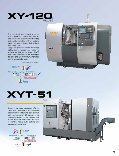
This middle size multi-turning center
is equipped with the sub-spindle X2
axis to enable superimposed cutting
and can be installed with an optional
sub-turret, which further helps short-
en turning time.
Compared to conventional machines,
higher-grade motors are used to
achieve an OD turning area of 0.87
mm2 (10% increase) on the main-spin-
dle side and 0.5 mm2 (13% increase)
on the sub-spindle side.
※Cutting amount×Feedrate.
From Blank to Finish with a Single Switch! Main-turret Y1
X1
(12-station)
Z1
Main-spindle (6") Sub-spindle (5")
CS1 CS2 Z2
X2
Both spindles are
fully synchronized.
Sub-turret
(12-station)
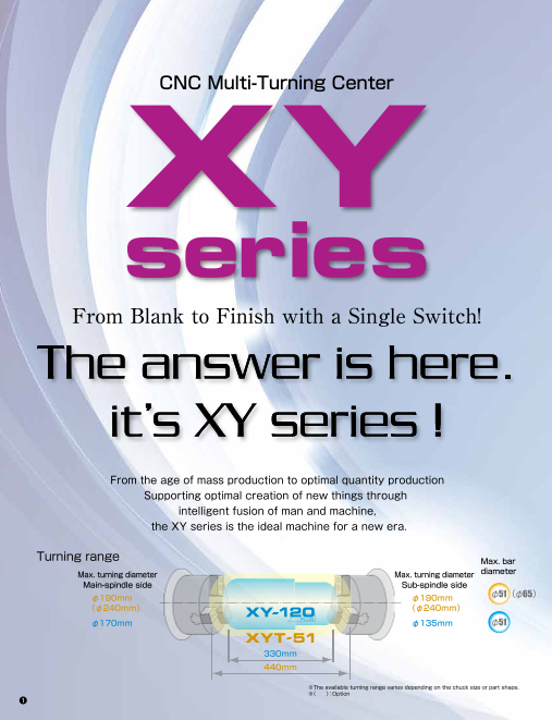
From the age of mass production to optimal quantity production
Supporting optimal creation of new things through Suited to bar work up to max. φ51 mm
intelligent fusion of man and machine, (φ65 mm), and able to accommodate
the XY series is the ideal machine for a new era. a maximum of 48 turning tools through
half indexing or 24 power tools.
Increasing motor output beyond that
Turning range of the existing machines allows it
Max. bar to handle heavy-duty cutting and
Max. turning diameter Max. turning diameter diameter compound machining.
Main-spindle side Sub-spindle side
φ190mm φ190mm φ51(φ65) Y1
X1 #1 Turret
(φ240mm) (φ240mm) Z1 (12-station)
φ170mm φ135mm φ51 Main-spindle (6") Sub-spindle (6")
C1 C2 A
Both spindles are
330mm fully synchronized.
440mm #2 Turret Z2
(12-station) X2
※The available turning range varies depending on the chuck size or part shape.
※( ):Option
1 2
Page3
CNC Multi-Turning Center
This middle size multi-turning center
is equipped with the sub-spindle X2
axis to enable superimposed cutting
and can be installed with an optional
sub-turret, which further helps short-
en turning time.
Compared to conventional machines,
higher-grade motors are used to
achieve an OD turning area of 0.87
mm2 (10% increase) on the main-spin-
dle side and 0.5 mm2 (13% increase)
on the sub-spindle side.
※Cutting amount×Feedrate.
From Blank to Finish with a Single Switch! Main-turret Y1
X1
(12-station)
Z1
Main-spindle (6") Sub-spindle (5")
CS1 CS2 Z2
X2
Both spindles are
fully synchronized.
Sub-turret
(12-station)
From the age of mass production to optimal quantity production
Supporting optimal creation of new things through Suited to bar work up to max. φ51 mm
intelligent fusion of man and machine, (φ65 mm), and able to accommodate
the XY series is the ideal machine for a new era. a maximum of 48 turning tools through
half indexing or 24 power tools.
Increasing motor output beyond that
Turning range of the existing machines allows it
Max. bar to handle heavy-duty cutting and
Max. turning diameter Max. turning diameter diameter compound machining.
Main-spindle side Sub-spindle side
φ190mm φ190mm φ51(φ65) Y1
X1 #1 Turret
(φ240mm) (φ240mm) Z1 (12-station)
φ170mm φ135mm φ51 Main-spindle (6") Sub-spindle (6")
C1 C2 A
Both spindles are
330mm fully synchronized.
440mm #2 Turret Z2
(12-station) X2
※The available turning range varies depending on the chuck size or part shape.
※( ):Option
1 2
Page4
Turning and milling available with the Y axis for power tools
Equipped with a Y axis and milling function, multi-turning operation equi-
valent to machining centers is possible. By using the Y axis, multi-turning
operations such as polar coordinate interpolation and cylindrical interpo-
lation which were conventionally difficult with turning machines are
made simpler with high precision.
Y-axis Power tool Power tool
cutting range storage capacity capacity Cylinder blocks
(car air-conditioners) Bar work automated FANUC Manual Guide i
with parts catcher installed for good and
± 35mm 12 tools / turret φ13mm,M8mm easy-to-use programming
The parts catcher can be configured to Cutting cycles for milling, turning, inclined
the most appropriate part-receiving timing cutting and more can be programmed
± 35mm 12 tools / #1 turret φ13mm,M12mm by programming and, if combined with an with ease and simulated in realistic
12 tools / #2 turret φ13mm,M12mm automatic bar feeder, enables extended graphical representation, which will
unmanned operation of bar work. dramatically shorten programming time.
Pistons
Sub-spindle provided for shaft work and
blank-to-finish cutting on both front and back faces
A sub-spindle having the same capability as the main-spindle enables
back face cutting of the second process in a single machine struc-
ture. Fully synchronized rotation of both spindles offers high precision Swivable operation panel Chip conveyor for chip
and uniform finish shaft work. Sleeves, body valves for good operability accumulation prevention
To reduce the operator's burden, a The slant bed structure of the XY series
Sub-spindle
Chuck size Spindle speed Stroke swivable operation panel is employed in assures a smooth flow of chips. Even if
cons i de ra t i on o f m in im i z i ng t he chips have complex shapes depending
operator’s motion area. Operations in on cutting conditions, using a chip
good posture support a strain-free, conveyor in combination can remove
5 inches Max.5,000min-1 440mm efficient and safe working environment. such chips smoothly from the machine.
Consideration to maintenance and environment
6 inches Max.5,000min-1 550mm For ease of maintenance and good operability, the chuck pressure regulating valve and lubrication
pump are arranged on the front face of the machine. A periodical inspection notice function notifies
Gear sleeves the time of battery replacement and hydraulic pump inspection to support control of maintenance
and help keep the machine in top condition all the time. In addition, the XY-120plus is equipped with
high-performance motors.
φ51 Specification φ65 Specification(OP)
Power Main-spindle Sub-spindle Power tools Main-spindle Sub-spindle Main-spindle Sub-spindle Power tools
AC7.5/5.5kW AC11/7.5kW(OP) AC5.5/3.7kW AC3.7/2.2/1.5kW AC18.5/15/11kW AC9/7.5/5.5kW AC18.5/15/11kW AC9/7.5/5.5kW AC3.7/2.2kW
Characteristic Max. 5,000min-1 Max. 4,000min-1 Max. 5,000min-1 Max. 4,000min-1 Max. 5,000min-1 MAX.5,000min-1 Max. 4,000min-1 MAX.4,000min-1 Max. 4,000min-1
12 12 12 4 21
750 3,000 1,5003.7kW 5 min rated 18.5kW S3 15% operating area 12 21 18.5kW S3 15% operating area 12 4 1,500
18 1,500 2,500
10 9kW S3 15% operating area 3.7kW 15min, S3 60%
T=118N・m 18 1,250 2,083
Curve operating area
10 7.5kW 15 min, S3 25% 10 11kW 15 min, S3 10 10 9kW S3 15% operating area
operating area 25% operating area T=141N・m
1,500 4,500 operating area
3 15 T=95.5N・m 3,500 15 T=114N・m 1,125 3,375
2,916 3
8 1,250 3,750 8 1,333 7.5kW Continuous 8
A wide range of high operating area 5.5kW 15 min, S3 40% 2.2kW 15 min, rated 15kW 8 T=57.3N・m 15kW 8 T=76N・m
operating area operating area 12 15min, S3 25% operating area 15min, S3 25% operating area
2,000 7.5kW 15min, S3 25% operating area 12 1,666 7.5kW 15min, S3 25% operating area
performance motors are 6 1,666 5.5kW Continuous 6 T=105.0N・m
T=70.5N・m 6 1,125 3,375 2 1.5kW Continuous rated (kW)
9 11kW Continuous (kW)6 2,000 (kW) (kW)6 1,500 (kW)2 2.2kW Continuous
(kW) operating area operating area 5.5kW Continuous 9 11kW Continuous
T=57.6N・m (kW) T=55.5N・m (kW) 1,500 3.7kW (kW) operating area operating area 5.5kW Continuous operating area
available according to your 4 T=42.0N・m 4 4 Continuous operating area
6 60min, S3 40% 4 operating area 4 operating are
operating area T=47.8N・m 6 60min, S3 40%
60 min, S3 40% T=46.6N・m 1 T=23.6N・m operating area T=62.7N・m
T=31.2N・m
needs from high horsepower 2 2 operating area 1
2 T=36.0N・m
T=24.0N・m T=13.9N・m 3 T=70N・m 2 T=35.0N・m
T=26.3N・m 3 T=84N・m T=46.7N・m
60 min, S3 40% 2 T=34.7N・m
T=52.5N・m 60min, S3 40% operating area T=63N・m
to high speed rotation. operating area T=9.54N・m
0 0 0 60 min, S3 40% operating area 60min, S3 40% operating area
0 0 0 0 0 0
0 1 2 3 4 5 0 1 2 3 4 5 0 1 2 3 4 5 0 1 2 3 4 0 1 2 3 4 5 0 1 2 3 4 5 0 1 2 3 4 5 0 1 2 3 4 5 0 1 2 3 4
Spindle speed (×1,000min-1) Spindle speed (×1,000min-1) Spindle speed (×1,000min-1) Spindle speed (×1,000min-1) Spindle speed (×1,000min-1) Spindle speed (×1,000min-1) Spindle speed (×1,000min-1) Spindle speed (×1,000min-1) Spindle speed (×1,000min-1)
3 4
Output
Output
Output
Output
Output
Output
Output
Output
Output
Page5
Turning and milling available with the Y axis for power tools
Equipped with a Y axis and milling function, multi-turning operation equi-
valent to machining centers is possible. By using the Y axis, multi-turning
operations such as polar coordinate interpolation and cylindrical interpo-
lation which were conventionally difficult with turning machines are
made simpler with high precision.
Y-axis Power tool Power tool
cutting range storage capacity capacity Cylinder blocks
(car air-conditioners) Bar work automated FANUC Manual Guide i
with parts catcher installed for good and
± 35mm 12 tools / turret φ13mm,M8mm easy-to-use programming
The parts catcher can be configured to Cutting cycles for milling, turning, inclined
the most appropriate part-receiving timing cutting and more can be programmed
± 35mm 12 tools / #1 turret φ13mm,M12mm by programming and, if combined with an with ease and simulated in realistic
12 tools / #2 turret φ13mm,M12mm automatic bar feeder, enables extended graphical representation, which will
unmanned operation of bar work. dramatically shorten programming time.
Pistons
Sub-spindle provided for shaft work and
blank-to-finish cutting on both front and back faces
A sub-spindle having the same capability as the main-spindle enables
back face cutting of the second process in a single machine struc-
ture. Fully synchronized rotation of both spindles offers high precision Swivable operation panel Chip conveyor for chip
and uniform finish shaft work. Sleeves, body valves for good operability accumulation prevention
To reduce the operator's burden, a The slant bed structure of the XY series
Sub-spindle
Chuck size Spindle speed Stroke swivable operation panel is employed in assures a smooth flow of chips. Even if
cons i de ra t i on o f m in im i z i ng t he chips have complex shapes depending
operator’s motion area. Operations in on cutting conditions, using a chip
good posture support a strain-free, conveyor in combination can remove
5 inches Max.5,000min-1 440mm efficient and safe working environment. such chips smoothly from the machine.
Consideration to maintenance and environment
6 inches Max.5,000min-1 550mm For ease of maintenance and good operability, the chuck pressure regulating valve and lubrication
pump are arranged on the front face of the machine. A periodical inspection notice function notifies
Gear sleeves the time of battery replacement and hydraulic pump inspection to support control of maintenance
and help keep the machine in top condition all the time. In addition, the XY-120plus is equipped with
high-performance motors.
φ51 Specification φ65 Specification(OP)
Power Main-spindle Sub-spindle Power tools Main-spindle Sub-spindle Main-spindle Sub-spindle Power tools
AC7.5/5.5kW AC11/7.5kW(OP) AC5.5/3.7kW AC3.7/2.2/1.5kW AC18.5/15/11kW AC9/7.5/5.5kW AC18.5/15/11kW AC9/7.5/5.5kW AC3.7/2.2kW
Characteristic Max. 5,000min-1 Max. 4,000min-1 Max. 5,000min-1 Max. 4,000min-1 Max. 5,000min-1 MAX.5,000min-1 Max. 4,000min-1 MAX.4,000min-1 Max. 4,000min-1
12 12 12 4 21
750 3,000 1,5003.7kW 5 min rated 18.5kW S3 15% operating area 12 21 18.5kW S3 15% operating area 12 4 1,500
18 1,500 2,500
10 9kW S3 15% operating area 3.7kW 15min, S3 60%
T=118N・m 18 1,250 2,083
Curve operating area
10 7.5kW 15 min, S3 25% 10 11kW 15 min, S3 10 10 9kW S3 15% operating area
operating area 25% operating area T=141N・m
1,500 4,500 operating area
3 15 T=95.5N・m 3,500 15 T=114N・m 1,125 3,375
2,916 3
8 1,250 3,750 8 1,333 7.5kW Continuous 8
A wide range of high operating area 5.5kW 15 min, S3 40% 2.2kW 15 min, rated 15kW 8 T=57.3N・m 15kW 8 T=76N・m
operating area operating area 12 15min, S3 25% operating area 15min, S3 25% operating area
2,000 7.5kW 15min, S3 25% operating area 12 1,666 7.5kW 15min, S3 25% operating area
performance motors are 6 1,666 5.5kW Continuous 6 T=105.0N・m
T=70.5N・m 6 1,125 3,375 2 1.5kW Continuous rated (kW)
9 11kW Continuous (kW)6 2,000 (kW) (kW)6 1,500 (kW)2 2.2kW Continuous
(kW) operating area operating area 5.5kW Continuous 9 11kW Continuous
T=57.6N・m (kW) T=55.5N・m (kW) 1,500 3.7kW (kW) operating area operating area 5.5kW Continuous operating area
available according to your 4 T=42.0N・m 4 4 Continuous operating area
6 60min, S3 40% 4 operating area 4 operating are
operating area T=47.8N・m 6 60min, S3 40%
60 min, S3 40% T=46.6N・m 1 T=23.6N・m operating area T=62.7N・m
T=31.2N・m
needs from high horsepower 2 2 operating area 1
2 T=36.0N・m
T=24.0N・m T=13.9N・m 3 T=70N・m 2 T=35.0N・m
T=26.3N・m 3 T=84N・m T=46.7N・m
60 min, S3 40% 2 T=34.7N・m
T=52.5N・m 60min, S3 40% operating area T=63N・m
to high speed rotation. operating area T=9.54N・m
0 0 0 60 min, S3 40% operating area 60min, S3 40% operating area
0 0 0 0 0 0
0 1 2 3 4 5 0 1 2 3 4 5 0 1 2 3 4 5 0 1 2 3 4 0 1 2 3 4 5 0 1 2 3 4 5 0 1 2 3 4 5 0 1 2 3 4 5 0 1 2 3 4
Spindle speed (×1,000min-1) Spindle speed (×1,000min-1) Spindle speed (×1,000min-1) Spindle speed (×1,000min-1) Spindle speed (×1,000min-1) Spindle speed (×1,000min-1) Spindle speed (×1,000min-1) Spindle speed (×1,000min-1) Spindle speed (×1,000min-1)
3 4
Output
Output
Output
Output
Output
Output
Output
Output
Output
Page6
Cycle time shortened with superimposed cutting The XY series machines have a spacious cutting chamber which makes
Superimposed in-machine work such as setup changes easier and provides a turning
Cutting X2 axis configuration is added to the sub-spindle slide to enable X- and Z-axis range flexible with varied workpieces.
superimposed cutting. An optional sub-turret further enables superimposed cutting
simultaneously on the main-spindle and the sub-spindle, which contributes to drastic Chip expulsion and dust-proofing are also improved compared to existing
cycle time reduction. (See the chart below.) machines, and the 60°angled cover under the turret reduces retention of
chips in the machine, and improves the chip removal capability which is
required by a mult i -turning center. Linear guides with excel lent
Main-spindle Cut
off Supply OD turning ID turning Drill Endmill Waiting dust-proofing are adopted.
Passing
Sub-spindle Waiting OD turning ID turning Drill Drill Discharge
Cover angle 60° Sliding slideway cover of
single-plate construction
Max. 50% time reduction
Simultaneous front and back face cutting is ※Excluding part supply, passing and discharge time
available by using the sub-spindle axis.
Main-spindle Cut
off Supply OD turning ID turning Drill Endmill
Passing
Sub-spindle OD turning ID turning Drill Drill Discharge
Superimposed cutting Cutting with sub-turret
Sufficient tool storage capacity
The 12-station main-turret with the intermediate indexing function has 24 tool
storage positions or if a sub-turret is installed 36 tool storage positions, reducing the
number of tool setup times that might be required frequently during various kinds
various volumes production.
A maximum of 12 power tools for drilling of up to φ13 mm can be installed. 60°
Sliding door adopted for ease of maintenance
The right side cover of the machine can be slid as a maintenance door.
A large maintenance area can be secured, which facilitates maintenance
or inspections and helps to reduce machine failures and trouble.
By applying two synchronized turning tools (for example, a rough turning tool and a
BALANCE CUT finish turning tool) simultaneously from both sides, part deflection can be dampened,
achieving high cutting precision and shorter cycle times.
Main-spindle side On the Sub-spindle side
#1 Turret
Use of bolt mount system (BMT45, 55)
#1 and #2 turrets are synchronized during The XYT-51 adopts the new global standard BMT system. This is a holder
OD turning for high precision balance cutting. securing system using four bolts and key grooves.
It is compatible with a wide range of attachments and a variety of tooling layouts
by each holder manufacturer, enabling turning and milling tailored to your needs
#2 Turret of production.
5 6
Conventional machine This machine
Page7
Cycle time shortened with superimposed cutting The XY series machines have a spacious cutting chamber which makes
Superimposed in-machine work such as setup changes easier and provides a turning
Cutting X2 axis configuration is added to the sub-spindle slide to enable X- and Z-axis range flexible with varied workpieces.
superimposed cutting. An optional sub-turret further enables superimposed cutting
simultaneously on the main-spindle and the sub-spindle, which contributes to drastic Chip expulsion and dust-proofing are also improved compared to existing
cycle time reduction. (See the chart below.) machines, and the 60°angled cover under the turret reduces retention of
chips in the machine, and improves the chip removal capability which is
required by a mult i -turning center. Linear guides with excel lent
Main-spindle Cut
off Supply OD turning ID turning Drill Endmill Waiting dust-proofing are adopted.
Passing
Sub-spindle Waiting OD turning ID turning Drill Drill Discharge
Cover angle 60° Sliding slideway cover of
single-plate construction
Max. 50% time reduction
Simultaneous front and back face cutting is ※Excluding part supply, passing and discharge time
available by using the sub-spindle axis.
Main-spindle Cut
off Supply OD turning ID turning Drill Endmill
Passing
Sub-spindle OD turning ID turning Drill Drill Discharge
Superimposed cutting Cutting with sub-turret
Sufficient tool storage capacity
The 12-station main-turret with the intermediate indexing function has 24 tool
storage positions or if a sub-turret is installed 36 tool storage positions, reducing the
number of tool setup times that might be required frequently during various kinds
various volumes production.
A maximum of 12 power tools for drilling of up to φ13 mm can be installed. 60°
Sliding door adopted for ease of maintenance
The right side cover of the machine can be slid as a maintenance door.
A large maintenance area can be secured, which facilitates maintenance
or inspections and helps to reduce machine failures and trouble.
By applying two synchronized turning tools (for example, a rough turning tool and a
BALANCE CUT finish turning tool) simultaneously from both sides, part deflection can be dampened,
achieving high cutting precision and shorter cycle times.
Main-spindle side On the Sub-spindle side
#1 Turret
Use of bolt mount system (BMT45, 55)
#1 and #2 turrets are synchronized during The XYT-51 adopts the new global standard BMT system. This is a holder
OD turning for high precision balance cutting. securing system using four bolts and key grooves.
It is compatible with a wide range of attachments and a variety of tooling layouts
by each holder manufacturer, enabling turning and milling tailored to your needs
#2 Turret of production.
5 6
Conventional machine This machine
Page8
T OOLING SYSTEM TURRET
Tooling System Turret interference
O.D./Face/Grooving tool□20
Clamp block C
O.D. holder S
O.D. holder(W)
O.D./Face tool□20 □20
Clamp block C
φ 1
2 6
0 5
Turning holder
Tap Tap holder 80
□1
6 16
Round hole bush 5
φ20 φ 3
13 75
φ16
Boring bar φ12 30
Maxφ25 φ10
φ8 12-station main-turret 75 210
Blank Plug
φ25 boring holder 25
100 105
φ100
5
φ11 85
U-drill Round hole bush
Maxφ25 φ20 120
φ
φ25 U-drill holder 110
5
φ1
3
φ17
0
Cut-off tool□20
95
30
Cut-off holder
φ13
5 φ5
1
Clamp block16(A) φ13 150
□ s
Straight drill Tool□16 2 t φ
0 6 2
5 00
Endmill 60
26 1
Maxφ13 Clamp block16(B) 20
Collet chuck φ
1 4 2
ER20-φD Face milling holder 0
5
Tap (also for rear milling) 0st 2 8
0 5
5
Max.M8
Sub-turret
Boring bar Round hole bush
Maxφ20 φ16 12-station sub-turre(t OP.)
Center φ12
φ10
straight φ8
drill φ6
Side milling holder Blank
Round hole bush
Boring bar φ16
Maxφ20 φ12
φ10
φ8
φ6
Blank Boring holde(r 24ST)
24ST
Clamp block16(A)
Tool□16
Clamp block16(B)
O.D. holder S(24ST)
Uni(t mm) Uni(t mm)
7 8
□16
φ115
φ20
φ20
φ2 1035 80
10
7 75
φ51
φ135
φ51
φ5
φ 151
□1
6
1
φ5
□1
6
φ115
φ580
Page9
T OOLING SYSTEM TURRET
Tooling System Turret interference
O.D./Face/Grooving tool□20
Clamp block C
O.D. holder S
O.D. holder(W)
O.D./Face tool□20 □20
Clamp block C
φ 1
2 6
0 5
Turning holder
Tap Tap holder 80
□1
6 16
Round hole bush 5
φ20 φ 3
13 75
φ16
Boring bar φ12 30
Maxφ25 φ10
φ8 12-station main-turret 75 210
Blank Plug
φ25 boring holder 25
100 105
φ100
5
φ11 85
U-drill Round hole bush
Maxφ25 φ20 120
φ
φ25 U-drill holder 110
5
φ1
3
φ17
0
Cut-off tool□20
95
30
Cut-off holder
φ13
5 φ5
1
Clamp block16(A) φ13 150
□ s
Straight drill Tool□16 2 t φ
0 6 2
5 00
Endmill 60
26 1
Maxφ13 Clamp block16(B) 20
Collet chuck φ
1 4 2
ER20-φD Face milling holder 0
5
Tap (also for rear milling) 0st 2 8
0 5
5
Max.M8
Sub-turret
Boring bar Round hole bush
Maxφ20 φ16 12-station sub-turre(t OP.)
Center φ12
φ10
straight φ8
drill φ6
Side milling holder Blank
Round hole bush
Boring bar φ16
Maxφ20 φ12
φ10
φ8
φ6
Blank Boring holde(r 24ST)
24ST
Clamp block16(A)
Tool□16
Clamp block16(B)
O.D. holder S(24ST)
Uni(t mm) Uni(t mm)
7 8
□16
φ115
φ20
φ20
φ2 1035 80
10
7 75
φ51
φ135
φ51
φ5
φ 151
□1
6
1
φ5
□1
6
φ115
φ580
Page10
STROKE TOOLING SYSTEM
Stroke-Related Drawing Tooling System
BMT45
Turning holder Boring holder
O.D./Face/Grooving tool □20
Clamp block C
O.D. holder
90 250 60 60 260 95 250 55 50 270
100 100
636 85
47 14 Max85
O.D./Face tool □20
11.1 37 11.1 37
330st
(Z-axis) 157.5 70 157.5 Clamp block C
(HAINBUCH) 250 80 (HAINBUCH) (HAINBUCH) 250 80 (HAINBUCH)
Colet Colet Colet Colet
JIS A2-6 169 JIS A2-4 JIS A2-6 169 JIS A2-4 Turning holder
(SMW) (SMW) (SMW)
6’chuck 5’chuck (SMW)
6’chuck 78 85 110 80 38 5’chuck Tap Tap holder
JIS A2-5 JIS A2-4 JIS A2-5 182 JIS A2-4
47 13
182
92 90 25 Round hole bush
Boring bar φ20
Maxφ25 φ16
φ12
440st 440st φ10
182 391 (Z2-axis) 147 182 391 (Z2-axis) 147 φ8 φ25 boring holder
720 720 Blank
U-drill Round hole bush
Maxφ25 φ20
φ16 12-station turret(BMT45)
φ12
φ10 φ25 U-drill holder
Z-Axis (Face) milling holder X-Axis (Side) milling holder φ8
Blank
Plug
65 250 85 52.5 267.5 150 250 50 270 Cut-off tool
□20
100 100
Cut-off holder (reverse) Cut-off holder (normal)
636
11.1 37 169 11.1 37
250 80 85 Max50 157.5
(HAINBUCH) (HAINBUCH) (HAINBUCH) 250 80 (HAINBUCH) Straight drill
Colet 169 Colet Colet
JIS A2-4 Colet
JIS A2-6 157.5 JIS A2-6 JIS A2-4 Endmill
Maxφ13
(SMW) 330st (SMW) (SMW)
6’chuck 5’chuck 6’chuck (SMW)
JIS A2-5 (Z-axis) JIS A2-4 JIS A2-5 5’chuck Collet chuck
JIS A2-4 AR20-φD
330st Tap Z-Axis(Face)milling holder
(Z-axis) Max.M12 (Doubles for back face use)
440st 440st
(Z2-axis) (Z2-axis)
182 391 147 182 391 147
720 720
X-Axis(Side)milling holder
Uni(t mm) Uni(t mm)
9 10
205 205
16 φ165
150st 75 165
(X-axis) 4 φ51 150st 125 165
25φ51 135 (X1-axis)
85 30
φ51
49.5 29.5
160 140 134 140
124 26
15 375
89.5 26
0st 375150st
(X2-axis) (X2-axis)
205 205
150st 80 165
(X1-axis)
150st 50 75 165
(X-axis)
φ51
130
85
160 140 160 140
124 26 375 4 120 26 375
150st 150st
(X2-axis) (X2-axis)
Page11
STROKE TOOLING SYSTEM
Stroke-Related Drawing Tooling System
BMT45
Turning holder Boring holder
O.D./Face/Grooving tool □20
Clamp block C
O.D. holder
90 250 60 60 260 95 250 55 50 270
100 100
636 85
47 14 Max85
O.D./Face tool □20
11.1 37 11.1 37
330st
(Z-axis) 157.5 70 157.5 Clamp block C
(HAINBUCH) 250 80 (HAINBUCH) (HAINBUCH) 250 80 (HAINBUCH)
Colet Colet Colet Colet
JIS A2-6 169 JIS A2-4 JIS A2-6 169 JIS A2-4 Turning holder
(SMW) (SMW) (SMW)
6’chuck 5’chuck (SMW)
6’chuck 78 85 110 80 38 5’chuck Tap Tap holder
JIS A2-5 JIS A2-4 JIS A2-5 182 JIS A2-4
47 13
182
92 90 25 Round hole bush
Boring bar φ20
Maxφ25 φ16
φ12
440st 440st φ10
182 391 (Z2-axis) 147 182 391 (Z2-axis) 147 φ8 φ25 boring holder
720 720 Blank
U-drill Round hole bush
Maxφ25 φ20
φ16 12-station turret(BMT45)
φ12
φ10 φ25 U-drill holder
Z-Axis (Face) milling holder X-Axis (Side) milling holder φ8
Blank
Plug
65 250 85 52.5 267.5 150 250 50 270 Cut-off tool
□20
100 100
Cut-off holder (reverse) Cut-off holder (normal)
636
11.1 37 169 11.1 37
250 80 85 Max50 157.5
(HAINBUCH) (HAINBUCH) (HAINBUCH) 250 80 (HAINBUCH) Straight drill
Colet 169 Colet Colet
JIS A2-4 Colet
JIS A2-6 157.5 JIS A2-6 JIS A2-4 Endmill
Maxφ13
(SMW) 330st (SMW) (SMW)
6’chuck 5’chuck 6’chuck (SMW)
JIS A2-5 (Z-axis) JIS A2-4 JIS A2-5 5’chuck Collet chuck
JIS A2-4 AR20-φD
330st Tap Z-Axis(Face)milling holder
(Z-axis) Max.M12 (Doubles for back face use)
440st 440st
(Z2-axis) (Z2-axis)
182 391 147 182 391 147
720 720
X-Axis(Side)milling holder
Uni(t mm) Uni(t mm)
9 10
205 205
16 φ165
150st 75 165
(X-axis) 4 φ51 150st 125 165
25φ51 135 (X1-axis)
85 30
φ51
49.5 29.5
160 140 134 140
124 26
15 375
89.5 26
0st 375150st
(X2-axis) (X2-axis)
205 205
150st 80 165
(X1-axis)
150st 50 75 165
(X-axis)
φ51
130
85
160 140 160 140
124 26 375 4 120 26 375
150st 150st
(X2-axis) (X2-axis)
Page12
TOOLING SYSTEM TURRET
Tooling System Turret interference
BMT55 BMT45
O.D./Face/Grooving tool □25
Clamp block
O.D. holder
O.D./Face tool □25
Clamp block TM112-10000
Turning holder
95 X1 Distance between
centers:300
Boring bar 75
Maxφ40 X2 Distance between
centers:315
50
g d
iam
ete
r
φ40 boring holderS
U-drill holder Round hole bush cki
n
Maxφ40 φ32 (T x c
huTM112-11000
M112-12000)
0 M
a .φ25
φ20 φ1
7
φ16
35s
t
φ12
φ10
Tap φ8
Tap holder Blank
Drill t
35sDrill holder
φ40 U-drill holder 12-station turret(BMT55)
75
Plug ia.
φ580 M
ax. turnin
g d
Cut-off tool
□25
75
Cut-off holder (reverse) Cut-off holder (normal)
50
Straight drill
Endmill
Maxφ20
Collet chuck
AR32-φD Z-Axis(Face)milling holder
(Doubles for back face use)
Tap
Max.M16
X-Axis(Side)milling holder
単位(mm) Uni(t mm)
11 12
□20
φ580 Max. turning dia.
75
φ25
(T
T MM 11 11 22 -- 11 21 00 00 00 )
TM112-10000
165
.
402
5
165
157
.5
150
237
.5
395
230
φ170
165
165
-10
000
12
TM1
80 φ
13
MAX
170
st
MAX
162
.5st
80
TM1
12-
100
00
0
φ1
7
φ13
Page13
TOOLING SYSTEM TURRET
Tooling System Turret interference
BMT55 BMT45
O.D./Face/Grooving tool □25
Clamp block
O.D. holder
O.D./Face tool □25
Clamp block TM112-10000
Turning holder
95 X1 Distance between
centers:300
Boring bar 75
Maxφ40 X2 Distance between
centers:315
50
g d
iam
ete
r
φ40 boring holderS
U-drill holder Round hole bush cki
n
Maxφ40 φ32 (T x c
huTM112-11000
M112-12000)
0 M
a .φ25
φ20 φ1
7
φ16
35s
t
φ12
φ10
Tap φ8
Tap holder Blank
Drill t
35sDrill holder
φ40 U-drill holder 12-station turret(BMT55)
75
Plug ia.
φ580 M
ax. turnin
g d
Cut-off tool
□25
75
Cut-off holder (reverse) Cut-off holder (normal)
50
Straight drill
Endmill
Maxφ20
Collet chuck
AR32-φD Z-Axis(Face)milling holder
(Doubles for back face use)
Tap
Max.M16
X-Axis(Side)milling holder
単位(mm) Uni(t mm)
11 12
□20
φ580 Max. turning dia.
75
φ25
(T
T MM 11 11 22 -- 11 21 00 00 00 )
TM112-10000
165
.
402
5
165
157
.5
150
237
.5
395
230
φ170
165
165
-10
000
12
TM1
80 φ
13
MAX
170
st
MAX
162
.5st
80
TM1
12-
100
00
0
φ1
7
φ13
Page14
TURRET STROKE
Turret interference Stroke-Related Drawing BMT45
BMT55
O.D. holder Z-Axis(Face)milling holder
915 915
455 460 455 460
143 Z1:500st 75 Z1:500st
393 50 35 45
192 192
TSC D42 flange (RIKEN)SAD-40
(2A Collet) A2-5 TSC D42 flange (RIKEN)SAD-40
A2-6 (2A Collet) A2-5
A2-6
(KITAGAWA)B206 (KITAGAWA)B206 (KITAGAWA)B206 (KITAGAWA)B206
A2-6 A2-5 A2-6 A2-5
φ21 145
0 145
189 189
X1 Distance between 398 45 50
64 centers:320 35
Z2:500st 148 Z2:500st 80
A:550st 172 172
67
60
φ2
10
Ma
x. c
huc
kin
g d
iam
ete
r X2 Distance between
centers:320 Boring holder, U-drill holder X-Axis(Side)milling holder
915 915
455 460 455 460
105 Z1:500st 205 Z1:500st
355 55 45
40
st
192 192
TSC D42 flange 理研SAD-40
t
35
s (2A Collet) A2-5 TSC D42 flange (RIKEN)SAD-40
A (2A Collet) A2-5
2-6 A2-6
(KITAGAWA)B206 北川B206
A2-6 A2-5 (KITAGAWA)B206 (KITAGAWA)B206
A2-6 A2-5
145 145
189 189
45 55 360
φ580 M
ax. turnin
g radius
Z2:500st 110 Z2:500st 210
172 172
67
Turning holder Cut-off holder
60 915 915
455 460 455 460
140.5 Z1:500st 140.5 Z1:500st
375 388
192 192
TSC D42 flange (RIKEN)SAD-40 TSC D42 flange (RIKEN)SAD-40
(2A Collet) A2-5 (2A Collet) A2-5
A2-6 A2-6
(KITAGAWA)B206 (KITAGAWA)B206 (KITAGAWA)B206 (KITAGAWA)B206
A2-6 A2-5 A2-6 A2-5
145 145
189 189
380 527
Z2:500st 130 Z2:500st 274.5
172 A:550st 172
単位(mm)
13 14
φ646 M □25ax. turning radius
41
φ634 limi φte 2
φ4
d 4
0
0Turning radius
φ210
395 395 395
X1:162.5st X1:162.5st
2.5 165 80 X1:162.5st
13
165 70 0.5 165 125
70 165 0.5 123 165
13
2.5 X2:170st 80 165 X2:170stX2:170st
402.5 402.5 402.5
395 395 395
X1:162.5st
X1:162.5st 165 75 50 X1:162.5st 165 75 7.5
165 127.5 105
127.5 165 112.5
X2:170st 50 75 165 7.5X2:170st 75 165X2:170st
402.5 402.5 402.5
19
0
0 19
0
0 41
16
0
0 22
16 60
MA
X
17
0s
t
0 0
41 22
10
0
19
19
0
2.5 φ1
6
MA
X
16
2.5
st
60
6
φ1
Page15
TURRET STROKE
Turret interference Stroke-Related Drawing BMT45
BMT55
O.D. holder Z-Axis(Face)milling holder
915 915
455 460 455 460
143 Z1:500st 75 Z1:500st
393 50 35 45
192 192
TSC D42 flange (RIKEN)SAD-40
(2A Collet) A2-5 TSC D42 flange (RIKEN)SAD-40
A2-6 (2A Collet) A2-5
A2-6
(KITAGAWA)B206 (KITAGAWA)B206 (KITAGAWA)B206 (KITAGAWA)B206
A2-6 A2-5 A2-6 A2-5
φ21 145
0 145
189 189
X1 Distance between 398 45 50
64 centers:320 35
Z2:500st 148 Z2:500st 80
A:550st 172 172
67
60
φ2
10
Ma
x. c
huc
kin
g d
iam
ete
r X2 Distance between
centers:320 Boring holder, U-drill holder X-Axis(Side)milling holder
915 915
455 460 455 460
105 Z1:500st 205 Z1:500st
355 55 45
40
st
192 192
TSC D42 flange 理研SAD-40
t
35
s (2A Collet) A2-5 TSC D42 flange (RIKEN)SAD-40
A (2A Collet) A2-5
2-6 A2-6
(KITAGAWA)B206 北川B206
A2-6 A2-5 (KITAGAWA)B206 (KITAGAWA)B206
A2-6 A2-5
145 145
189 189
45 55 360
φ580 M
ax. turnin
g radius
Z2:500st 110 Z2:500st 210
172 172
67
Turning holder Cut-off holder
60 915 915
455 460 455 460
140.5 Z1:500st 140.5 Z1:500st
375 388
192 192
TSC D42 flange (RIKEN)SAD-40 TSC D42 flange (RIKEN)SAD-40
(2A Collet) A2-5 (2A Collet) A2-5
A2-6 A2-6
(KITAGAWA)B206 (KITAGAWA)B206 (KITAGAWA)B206 (KITAGAWA)B206
A2-6 A2-5 A2-6 A2-5
145 145
189 189
380 527
Z2:500st 130 Z2:500st 274.5
172 A:550st 172
単位(mm)
13 14
φ646 M □25ax. turning radius
41
φ634 limi φte 2
φ4
d 4
0
0Turning radius
φ210
395 395 395
X1:162.5st X1:162.5st
2.5 165 80 X1:162.5st
13
165 70 0.5 165 125
70 165 0.5 123 165
13
2.5 X2:170st 80 165 X2:170stX2:170st
402.5 402.5 402.5
395 395 395
X1:162.5st
X1:162.5st 165 75 50 X1:162.5st 165 75 7.5
165 127.5 105
127.5 165 112.5
X2:170st 50 75 165 7.5X2:170st 75 165X2:170st
402.5 402.5 402.5
19
0
0 19
0
0 41
16
0
0 22
16 60
MA
X
17
0s
t
0 0
41 22
10
0
19
19
0
2.5 φ1
6
MA
X
16
2.5
st
60
6
φ1
Page16
STROKE FLOOR SPACE
Stroke-Related Drawing BMT55 Floor Space Drawing
O.D. holder Z-Axis(Face)milling holder
R840
915 915
455 460 455 460
128 Z1:500st 75 Z1:500st
378 40 45 45
214 214
(RIKEN)SAD-65 (RIKEN)SAD-65 (RIKEN)SAD-65 (RIKEN)SAD-65
A2-8 A2-6 A2-8 A2-6
SMW BHM210 SMW BHM210 SMW BHM210 SMW BHM210
A2-8 A2-6 A2-8 A2-6
227 190
232 232
383 45 45 40
Z2:500st 133 Z2:500st 80
A:550st 219 219
Boring holder, U-drill holder X-Axis(Side)milling holder
915 915
455 460 455 460 520 1,550 560
105 Z1:500st 205 Z1:500st 630 (200) 200 2,015 415
355 55 45 330 1,025 2,630 830
200 (3,660)
Uni(t mm)
214 214
(RIKEN)SAD-65 (RIKEN)SAD-65 (RIKEN)SAD-65 (RIKEN)SAD-65
A2-8 A2-6 A2-8 A2-6
SMW BHM210 SMW BHM210 SMW BHM210 SMW BHM210
A2-8 A2-6 A2-8 A2-6
227 190
232 232
45 55 360
Z2:500st 110 Z2:500st 210
219 219
Turning holder Cut-off holder
915 915
455 460 455 460 2,988(3,000:φ65 specification)
95 Z1:500st 132.5 Z1:500st
345 380 3,160(3,172:φ65 specification)
80
214 214 (1,093)
(RIKEN)SAD-65 (RIKEN)SAD-65 (RIKEN)SAD-65 (RIKEN)SAD-65
A2-8 A2-6 A2-8 A2-6
SMW BHM210 SMW BHM210 SMW BHM210 SMW BHM210
A2-8 A2-6 A2-8 A2-6
227 227
232 232
350 535 695 4,078(4,090:φ65 specification)
Z2:500st 100 Z2:500st 282.5
219 A:550st 219
Uni(t mm)
15 16
410 410 410
X1:162.5st X1:162.5st X1:162.5st
21.5 190 60 13
190 36 10.5 190 95
3
36 190 95 190
14 13
X2:170st X2:170st 60 190 X2:170st
410 410 410
410 410 410
X1:162.5st X1:162.5st
X1:162.5st
60 190 60 2.5
190 130 190 67 93
130 190 93 67 190
60 10 60 190X2:170st
X2:170st X2:170st
410 410 410
1,455 310 1,400
1,240 1,050
955
2,163
2,130 380
2,158
10
(48)
1,000
800 367 567
1,410 215 1,410 105 810 755
1,730 80 158
1,950
0
R51
Page17
STROKE FLOOR SPACE
Stroke-Related Drawing BMT55 Floor Space Drawing
O.D. holder Z-Axis(Face)milling holder
R840
915 915
455 460 455 460
128 Z1:500st 75 Z1:500st
378 40 45 45
214 214
(RIKEN)SAD-65 (RIKEN)SAD-65 (RIKEN)SAD-65 (RIKEN)SAD-65
A2-8 A2-6 A2-8 A2-6
SMW BHM210 SMW BHM210 SMW BHM210 SMW BHM210
A2-8 A2-6 A2-8 A2-6
227 190
232 232
383 45 45 40
Z2:500st 133 Z2:500st 80
A:550st 219 219
Boring holder, U-drill holder X-Axis(Side)milling holder
915 915
455 460 455 460 520 1,550 560
105 Z1:500st 205 Z1:500st 630 (200) 200 2,015 415
355 55 45 330 1,025 2,630 830
200 (3,660)
Uni(t mm)
214 214
(RIKEN)SAD-65 (RIKEN)SAD-65 (RIKEN)SAD-65 (RIKEN)SAD-65
A2-8 A2-6 A2-8 A2-6
SMW BHM210 SMW BHM210 SMW BHM210 SMW BHM210
A2-8 A2-6 A2-8 A2-6
227 190
232 232
45 55 360
Z2:500st 110 Z2:500st 210
219 219
Turning holder Cut-off holder
915 915
455 460 455 460 2,988(3,000:φ65 specification)
95 Z1:500st 132.5 Z1:500st
345 380 3,160(3,172:φ65 specification)
80
214 214 (1,093)
(RIKEN)SAD-65 (RIKEN)SAD-65 (RIKEN)SAD-65 (RIKEN)SAD-65
A2-8 A2-6 A2-8 A2-6
SMW BHM210 SMW BHM210 SMW BHM210 SMW BHM210
A2-8 A2-6 A2-8 A2-6
227 227
232 232
350 535 695 4,078(4,090:φ65 specification)
Z2:500st 100 Z2:500st 282.5
219 A:550st 219
Uni(t mm)
15 16
410 410 410
X1:162.5st X1:162.5st X1:162.5st
21.5 190 60 13
190 36 10.5 190 95
3
36 190 95 190
14 13
X2:170st X2:170st 60 190 X2:170st
410 410 410
410 410 410
X1:162.5st X1:162.5st
X1:162.5st
60 190 60 2.5
190 130 190 67 93
130 190 93 67 190
60 10 60 190X2:170st
X2:170st X2:170st
410 410 410
1,455 310 1,400
1,240 1,050
955
2,163
2,130 380
2,158
10
(48)
1,000
800 367 567
1,410 215 1,410 105 810 755
1,730 80 158
1,950
0
R51
Page18
SPECIFICATION
Machine Specifications Controller Specifications
φ51 THRU,BMT45 Specification φ65 THRU,BMT55 Specification(OP) Item TAKAMAZ&FANUC 0i-TD TAKAMAZ & FANUC 32i-B
Item Unit Main-spindle Main-spindle
Main-spindle Sub-spindle Main-spindle Sub-spindle Controlled axes 7 axes(X1, Z1, C1, Y, X2, Z2, C2) 8 axes (X1, Z1, C1, Y, X2, Z2, C2, A)
Simultaneously controllable axes Simultaneous 4 axes
Max. turning diameter mm φ170 φ135 φ190 φ240 Least input increment 0.001mm (X in diameter)
Max. turning length mm 330 150(440:One-side operation) 150(440:One-side operation) Least command increment X: 0.0005mm Z, Y: 0.001mm X: 0.0005mm Z, Y, A: 0.001mm C: 0.001deg.
Max. bar diameter mm φ42 (φ51) φ20 φ51 φ42 φ65 φ51 Auxiliary function M3 digits
Chuck size Inch Collet, 6 Collet, 5 Collet, 6 8 Spindle function S4 digits
Spindle nose JIS A2-5 (A2-6) A2-4 A2-6 A2-5 A2-8 A2-6 Tool function T4 digits
Spindle bearing I.D. mm φ85 (φ100) φ65 φ100 φ85 φ120 φ100 Tape code EIA(RS232C) / ISO(840)automatic recognition
Through-hole on spindle mm φ52 (φ61) φ36 φ52 φ43 φ66 φ52 Cutting feedrate 1~ 5,000mm/min 1~7,000mm/min
Spindle speed min-1 Max.5,000(Max.4,000) Max.5,000 Max.5,000 Max.4,000 Command system Incremental / Absolute
Type 12-station turret 24st. 12-station turret 24st. BMT45 12-station turret 24st. BMT55 Linear interpolation G01
Tool shank mm □20 □20 □25 Circular interpolation G02, G03
Boring holder I.D. mm φ25 φ25 φ40 Cutting feedrate override 0~ 150%
Max. stroke mm X1:150 Z1:330 Y:±35 X1:162.5 Z1:500 Y:±35 X1:162.5 Z1:500 Y:+40-35 Rapid traverse override F0, 100% F0, 25%, 50%, 100%
X2:150 Z2:440 X2:170 Z2:500 A:550 X2:170 Z2:500 A:550 Program number 4 digits Program file name 32 characters
Rapid traverse rate m/min X1:18 Z1:24 Y:12
X2:18 Z2:18 X:18 Z:30 Y:12 A:30 X:18 Z:30 Y:12 A:30 Backlash compensation 0~ 9,999μm
Program memory capacity 1Mbyte(2,560m)(Dual systems total) 64Kbyte(160m)(Dual systems total)
Tool storage capacity pcs. 12 12 12 Tool offsets 128 sets(Dual systems total) 99 sets(Dual systems total)
Rotation speed min-1 Max.4,000 Max.4,000 Max.4,000 Registered programs 800 pcs.(Dual systems total) 63 pcs(. Dual systems total)
Drill mm φ13 φ13 φ20 Tool geometry /Wear offset Standard
C a pacity Endmill mm φ13 φ13 φ20 Canned cycle G90, G92, G94
Tap mm M8 M12 M16 Radius designation on arc Standard
Rapid traverse rate deg./min 21,600 24,000 24,000 Tool offset measurement input Standard
C axis motor kW Cs-axis AC 0.75 - Background editing Standard
Spindle motor kW AC7.5/5.5(AC11/7.5) AC5.5/3.7 AC18.5/15/11 AC9/7.5/5.5 AC18.5/15/11 AC9/7.5/5.5 Direct drawing dimension programming Standard Option
Feed motor kW X1:AC1.2 Z1:AC1.8 Y:AC0.75
X2:AC0.75 Z2:AC1.2 X:1.8 Z:1.8 Y:1.4 A:1.2 X:1.8 Z:1.8 Y:1.4 A:1.2 Custom macro Standard
Custom macro common variables #100~#199, #500~#999 Option
Coolant motor kW AC 0.25/0.25 AC 0.4 AC 0.4 Pattern data input Standard ー
Hydraulic motor kW AC1.5 AC 0.75 AC 0.75 Nose R compensation G40, G41, G42
Power tools motor kW AC3.7/2.2/1.5 AC3.7/2.2 AC3.7/2.2 Inch /Metric conversion G20/G21 Option
Spindle center height mm 1,050 1,240 1,240 Programmable data input G10
L×W×H mm 2,630 × 1,950 × 1,730 2,988×2,163×2,158(3,490※1) 3,000×2,163×2,158 Run hour / Parts count display Standard Option
Machine weight kg 4,500 7,400(8,250※1) 7,500 Extended part program editing Standard
Total electric capacity KVA 27(31) 44 44 Multiple repetitive cycle G70~G76
※1 Gantry Loader type ( ):Option Multiple repetitive cycleⅡ Pocket-shaped Option
Spindle synchronous control Standard
Standard Accessories Sub-spindle torque skip Standard
Y-axis offset Standard
Canned drilling cycle Standard
Constant surface speed control G96, G97
□Boring holder 2 sets Continuous thread cutting G32
□O.D. holder 2 sets Variable lead thread cutting G34 Option
□Cut-off holder 1 set Thread cutting retract Standard Option
□Collet flange 1 set ea(. Main, Sub) Clock function Standard
□Hydraulic chuck Option Help function Standard
□Hydraulic chucking cylinder ー 1 set ea(. Main, Sub) Alarm history display 50 pcs.
□Y-axis function 1 set(Main) 1 set(#1 Turret) Self-diagnosis function Standard
□Spindle indexing device Cs-axis 1 set ea(. Main, Sub) Cs-axis 1 set ea(. Main, Sub) Sub-program call Up to 10 loops
□Power tools drive unit 1 set(Main) 1 set(For both turrets) Decimal point input Standard
□Sub-spindle 1 set 2nd reference point return G30
□Coolant unit 1 set(200lit.) 1 set(360lit.) Work coordinate system setting G50, G54~G59
□Service tool kit 1 set Rigid tapping For Power Tool only
□TAKAMAZ Instruction manual 1 set Polar coordinate interpolation Standard
Cylindrical interpolation Standard
Stored stroke check 1 Standard
Optional Accessories Stored stroke check 2,3 Standard
Input / Output interface USB Flash Memory, Memory card, Ethernet
Alarm message Standard
□Tool holders ○ Graphic display Standard
□Stroke adjusting cylinder ○ Spindle orientation Standard
□Collet chucks ○ Conversational programming with graphic function Standard ー
□Hydraulic chucks ○(Main:6 Inch Sub:5 Inch) ○ Abnormal load detection Standard
□Chuck clamp detector ○ (Standard) Overlap Cutting Process Standard
□Sub-spindle parts ejector ○ (Standard) Balance cut ー G68, 69
□Sub turret(□16, φ20) ○(12-station) ー Manual handle trace Standard
□TAKAMAZ loader system ○ ー Automatic data backup Max.3
□Bar feeder system ○ Automatic screen deletion function Standard
□Unloader unit(Out-conveyor) ○ (Standard) TAKAMAZ management support function Work / Tool counter, Tool load monitor, Others
□Work set detector ○ TAKAMAZ maintenance function Standard
□Cut-off check device ○ FANUC set of manuals CD-ROM DVD-ROM
□Power tools(Face / Side milling) ○ ー
□Chip conveyor Optional Specifications
(Floor type/Spiral type) ○(Right)
□Front air blower ○
□Rear air blower ○ ー Item TAKAMAZ&FANUC 0i-TD TAKAMAZ & FANUC 32i-B
□Rear coolant unit ○ Tool life management
□Signal light(1-tier / 2-tier / 3-tier) ○ Multiple M codes in one block Max. 3
□Automatic fire extinguisher ○ Dynamic graphic display※
□Automatic power shut-off device ○ Manual guide i※
□Automatic door system ○ ー Helical interpolation
□Special color ○ RS232C
□Others※ ○ FANUC instruction manuals Bound
17 ※For more information on attachments, consult our sales representative. ※These cannot be used together. 18
Size Motors C-axis Power tools Tool post Spindle Capacity
Page19
SPECIFICATION
Machine Specifications Controller Specifications
φ51 THRU,BMT45 Specification φ65 THRU,BMT55 Specification(OP) Item TAKAMAZ&FANUC 0i-TD TAKAMAZ & FANUC 32i-B
Item Unit Main-spindle Main-spindle
Main-spindle Sub-spindle Main-spindle Sub-spindle Controlled axes 7 axes(X1, Z1, C1, Y, X2, Z2, C2) 8 axes (X1, Z1, C1, Y, X2, Z2, C2, A)
Simultaneously controllable axes Simultaneous 4 axes
Max. turning diameter mm φ170 φ135 φ190 φ240 Least input increment 0.001mm (X in diameter)
Max. turning length mm 330 150(440:One-side operation) 150(440:One-side operation) Least command increment X: 0.0005mm Z, Y: 0.001mm X: 0.0005mm Z, Y, A: 0.001mm C: 0.001deg.
Max. bar diameter mm φ42 (φ51) φ20 φ51 φ42 φ65 φ51 Auxiliary function M3 digits
Chuck size Inch Collet, 6 Collet, 5 Collet, 6 8 Spindle function S4 digits
Spindle nose JIS A2-5 (A2-6) A2-4 A2-6 A2-5 A2-8 A2-6 Tool function T4 digits
Spindle bearing I.D. mm φ85 (φ100) φ65 φ100 φ85 φ120 φ100 Tape code EIA(RS232C) / ISO(840)automatic recognition
Through-hole on spindle mm φ52 (φ61) φ36 φ52 φ43 φ66 φ52 Cutting feedrate 1~ 5,000mm/min 1~7,000mm/min
Spindle speed min-1 Max.5,000(Max.4,000) Max.5,000 Max.5,000 Max.4,000 Command system Incremental / Absolute
Type 12-station turret 24st. 12-station turret 24st. BMT45 12-station turret 24st. BMT55 Linear interpolation G01
Tool shank mm □20 □20 □25 Circular interpolation G02, G03
Boring holder I.D. mm φ25 φ25 φ40 Cutting feedrate override 0~ 150%
Max. stroke mm X1:150 Z1:330 Y:±35 X1:162.5 Z1:500 Y:±35 X1:162.5 Z1:500 Y:+40-35 Rapid traverse override F0, 100% F0, 25%, 50%, 100%
X2:150 Z2:440 X2:170 Z2:500 A:550 X2:170 Z2:500 A:550 Program number 4 digits Program file name 32 characters
Rapid traverse rate m/min X1:18 Z1:24 Y:12
X2:18 Z2:18 X:18 Z:30 Y:12 A:30 X:18 Z:30 Y:12 A:30 Backlash compensation 0~ 9,999μm
Program memory capacity 1Mbyte(2,560m)(Dual systems total) 64Kbyte(160m)(Dual systems total)
Tool storage capacity pcs. 12 12 12 Tool offsets 128 sets(Dual systems total) 99 sets(Dual systems total)
Rotation speed min-1 Max.4,000 Max.4,000 Max.4,000 Registered programs 800 pcs.(Dual systems total) 63 pcs(. Dual systems total)
Drill mm φ13 φ13 φ20 Tool geometry /Wear offset Standard
C a pacity Endmill mm φ13 φ13 φ20 Canned cycle G90, G92, G94
Tap mm M8 M12 M16 Radius designation on arc Standard
Rapid traverse rate deg./min 21,600 24,000 24,000 Tool offset measurement input Standard
C axis motor kW Cs-axis AC 0.75 - Background editing Standard
Spindle motor kW AC7.5/5.5(AC11/7.5) AC5.5/3.7 AC18.5/15/11 AC9/7.5/5.5 AC18.5/15/11 AC9/7.5/5.5 Direct drawing dimension programming Standard Option
Feed motor kW X1:AC1.2 Z1:AC1.8 Y:AC0.75
X2:AC0.75 Z2:AC1.2 X:1.8 Z:1.8 Y:1.4 A:1.2 X:1.8 Z:1.8 Y:1.4 A:1.2 Custom macro Standard
Custom macro common variables #100~#199, #500~#999 Option
Coolant motor kW AC 0.25/0.25 AC 0.4 AC 0.4 Pattern data input Standard ー
Hydraulic motor kW AC1.5 AC 0.75 AC 0.75 Nose R compensation G40, G41, G42
Power tools motor kW AC3.7/2.2/1.5 AC3.7/2.2 AC3.7/2.2 Inch /Metric conversion G20/G21 Option
Spindle center height mm 1,050 1,240 1,240 Programmable data input G10
L×W×H mm 2,630 × 1,950 × 1,730 2,988×2,163×2,158(3,490※1) 3,000×2,163×2,158 Run hour / Parts count display Standard Option
Machine weight kg 4,500 7,400(8,250※1) 7,500 Extended part program editing Standard
Total electric capacity KVA 27(31) 44 44 Multiple repetitive cycle G70~G76
※1 Gantry Loader type ( ):Option Multiple repetitive cycleⅡ Pocket-shaped Option
Spindle synchronous control Standard
Standard Accessories Sub-spindle torque skip Standard
Y-axis offset Standard
Canned drilling cycle Standard
Constant surface speed control G96, G97
□Boring holder 2 sets Continuous thread cutting G32
□O.D. holder 2 sets Variable lead thread cutting G34 Option
□Cut-off holder 1 set Thread cutting retract Standard Option
□Collet flange 1 set ea(. Main, Sub) Clock function Standard
□Hydraulic chuck Option Help function Standard
□Hydraulic chucking cylinder ー 1 set ea(. Main, Sub) Alarm history display 50 pcs.
□Y-axis function 1 set(Main) 1 set(#1 Turret) Self-diagnosis function Standard
□Spindle indexing device Cs-axis 1 set ea(. Main, Sub) Cs-axis 1 set ea(. Main, Sub) Sub-program call Up to 10 loops
□Power tools drive unit 1 set(Main) 1 set(For both turrets) Decimal point input Standard
□Sub-spindle 1 set 2nd reference point return G30
□Coolant unit 1 set(200lit.) 1 set(360lit.) Work coordinate system setting G50, G54~G59
□Service tool kit 1 set Rigid tapping For Power Tool only
□TAKAMAZ Instruction manual 1 set Polar coordinate interpolation Standard
Cylindrical interpolation Standard
Stored stroke check 1 Standard
Optional Accessories Stored stroke check 2,3 Standard
Input / Output interface USB Flash Memory, Memory card, Ethernet
Alarm message Standard
□Tool holders ○ Graphic display Standard
□Stroke adjusting cylinder ○ Spindle orientation Standard
□Collet chucks ○ Conversational programming with graphic function Standard ー
□Hydraulic chucks ○(Main:6 Inch Sub:5 Inch) ○ Abnormal load detection Standard
□Chuck clamp detector ○ (Standard) Overlap Cutting Process Standard
□Sub-spindle parts ejector ○ (Standard) Balance cut ー G68, 69
□Sub turret(□16, φ20) ○(12-station) ー Manual handle trace Standard
□TAKAMAZ loader system ○ ー Automatic data backup Max.3
□Bar feeder system ○ Automatic screen deletion function Standard
□Unloader unit(Out-conveyor) ○ (Standard) TAKAMAZ management support function Work / Tool counter, Tool load monitor, Others
□Work set detector ○ TAKAMAZ maintenance function Standard
□Cut-off check device ○ FANUC set of manuals CD-ROM DVD-ROM
□Power tools(Face / Side milling) ○ ー
□Chip conveyor Optional Specifications
(Floor type/Spiral type) ○(Right)
□Front air blower ○
□Rear air blower ○ ー Item TAKAMAZ&FANUC 0i-TD TAKAMAZ & FANUC 32i-B
□Rear coolant unit ○ Tool life management
□Signal light(1-tier / 2-tier / 3-tier) ○ Multiple M codes in one block Max. 3
□Automatic fire extinguisher ○ Dynamic graphic display※
□Automatic power shut-off device ○ Manual guide i※
□Automatic door system ○ ー Helical interpolation
□Special color ○ RS232C
□Others※ ○ FANUC instruction manuals Bound
17 ※For more information on attachments, consult our sales representative. ※These cannot be used together. 18
Size Motors C-axis Power tools Tool post Spindle Capacity
Page20
CNC Multi-Turning Center
XYseries
TAKAMATSU MACHINERY CO., LTD. TAKAMAZ MACHINERY MEXICO, S.A.DE C.V.
■HEAD OFFICE & PLANT AVENIDA DE LOS INDUSTRIALES 522, LOCAL 4, INDUSTRIAL JULIAN DE OBREGON, 37290 LEON,
1-8 ASAHIGAOKA HAKUSAN-CITY ISHIKAWA JAPAN. 924-8558 TEL +81-(0)76-207-6155 FAX +81-(0)76-274-1418 GUANAJUATO MEXICO
■ASAHI PLANT TEL +52-477-784-0468
4-13 ASAHIGAOKA HAKUSAN-CITY ISHIKAWA JAPAN. 924-0004 TEL +81-(0)76-274-0123 FAX +81-(0)76-274-8530 TAKAMATSU MACHINERY VIETNAM CO., LTD
TAKAMATSU MACHINERY U.S.A., INC. NO.76 M HOANG QUOC VIET, PHU MY WARD, DISTRICT 7, HO CHI MINH CITY, VIETNAM
■CHICAGO HEAD OFFICE TEL +84-(0)28-3620-5671 FAX +84-(0)28-3620-5673
1280 LANDMEIER ROAD ELK GROVE VILLAGE, IL 60007 USA TEL +1-(0)847-981-8577 FAX +1-(0)847-981-8599
TAKAMAZ MACHINERY EUROPE GmbH
IM HÜLSENFELD 19, 40721 HILDEN, GERMANY TEL +49-(0)2103-789-4882 FAX +49-(0)2103-789-4883
TAKAMAZ MACHINERY( HANGZHOU) CO., LTD.
■HANGZHOU HEAD OFFICE
NO.6800, JIANGDONG 3RD ROAD, JIANGDONG INDUSTRIAL PARK, XIAOSHAN, HANGZHOU, ZHEJIANG, CHINA
TEL +86-(0)571-8287-9709 FAX +86-(0)571-8215-3732 Precautions Related to Foreign Exchange and Foreign Trade Control Laws
TAKAMATSU MACHINERY( THAILAND) CO., LTD. This product (machine and ancillary equipment) may fall under the category of controlled
goods by the foreign exchange and foreign trade control laws.
■BANGKOK HEAD OFFICE As such, the exportation must be authorized by the Japanese government as stipulated in the laws
888/59 MOO 9, TAMBOL BANGPLA, AMPHUR BANGPLEE, SAMUTPRAKARN PROVINCE, THAILAND This product is manufactured in accordance with the regulations and standards that prevail in the
TEL +66-(0)2-136-7831 FAX +66-(0)2-136-7834 country or region of destination.
PT. TAKAMAZ INDONESIA The user must not export, sell, or relocate the product, to anycountry with different regulations or standards.
JL. FESTIVAL BOULEVARD BLOK AA 11 NO.30,31 GRAND WISATA TAMBUN, BEKASI 17510
TEL +62-(0)21-8261-6431 FAX +62-(0)21-8261-6430
23.11.1B(O)