


TAKAMAZ XTT-500/500M Catalog
Product Catalog
CNC 1 Spindle 2 Turret Precision Lathe
Document Information
| Document Title | TAKAMAZ XTT-500/500M Catalog |
|---|---|
| Document Type | Product Catalog |
| File size | 2Mb |
| Category | |
| Company | TAKAMAZ (TAKAMATSU MACHINERY Co.,ltd) (Documents List) |
Documents related to this company


Document Contents
Page1
CNC1Spindle2Turret Controller Specifications
Precision Lathe Item XTT-500 XTT-500M
TAKAMAZ & FANUC 0i-TF CNC1Spindle2Turret
Controlled axes 4 axes(X1, X2, Z1, Z2) 5 axes(X1, Z1, C, X2, Z2)
Simultaneously controllable axes Simultaneous 2 axes(× 2)Simultaneous 3 axes (× 2) Precision Lathe
Machine Specifications Least input increment 0.001mm (X in diameter)
Least command increment X : 0.0005mm Z : 0.001mm
Item Unit XTT-500 XTT-500M Auxiliary function M-code 3 digit
Max. turning diameter mm φ210 Spindle function S-code 4 digit
Max. turning length mm 450 400 Tool function T-code 4 digit
Tape code EIA(RS232C)/ISO(840)automatic recognition
Max. bar diameter mm φ42, φ51(φ65) φ42, φ51 Cutting feedrate 1~5,000mm/min
Chuck size inch Collet, 8(10) Collet, 8 Command system Incremental/Absolute
Spindle nose JIS A2-6(A2-8) A2-6 Linear interpolation G01
Spindle bearing I.D. mm φ100(φ120) φ100 Circular interpolation G02, G03
Through-hole on spindle mm φ61(φ80) φ61 Cutting feedrate override 0~150%
Rapid traverse override F0, 100%
Spindle speed min -1 Max.4,000(3,500) Max.4,000 Program file name 32 characters
Type 8-station turret×2 Backlash compensation 0~9,999μm
Tool shank mm □25 Program memory capacity 1Mbyte (2,560m)(Dual systems total)
Boring holder I.D. mm φ32 Tool offsets 128 sets (Dual systems total)
Registered programs
Max. stroke mm X:105 Z:450 800 pcs. (Dual systems total)
Tool geometry/Wear offset Standard
Rapid traverse rate m/min X:18 Z:24 Canned cycle G90, G92, G94
Tool storage capacity pcs. - 4(one side) Radius designation on arc Standard
Rotation speed min -1 - Max.4,000 Tool offset measurement input Standard
Drill mm - φ10 Background editing Standard
Direct drawing dimension programming Standard
Capacity Endmill mm - φ10 Custom macro Standard
Tap mm - M4~M8 Custom macro common variables #100~#199, #500~#999
Rapid traverse rate deg./min - 18,000 Pattern data input Standard
C-axis
C-axis motor kW - AC 0.5 Nose R compensation G40, G41, G42
Inch/Metric conversion
Spindle motor kW AC15/11(18.5/15) AC15/11 G20/G21
Programmable data input G10
Feed motor kW X:AC1.2 Z:AC1.8 Run hour/Parts count display Standard
Coolant motor kW AC 0.4×2 Extended part program editing Standard
Hydraulic motor kW AC1.5 Multiple repetitive cycle G70~G76
Power tools motor kW - AC1.8 Multiple repetitive cycle Ⅱ Pocket-shaped
Canned drilling cycle Standard
L×W×H mm
Size 1,695×1,830×1,850 Constant surface speed control G96, G97
Machine weight kg 4,600 4,800 Continuous thread cutting G32
Total electric capacity KVA 26 28 Variable lead thread cutting G34
( ):Option Thread cutting retract Standard
Clock function Standard
Standard Accessories Help function Standard
Alarm history display 50 pcs.
□Clamp block ……………………… 16sets □Power tools drive uni(t 500M) … 1set Self-diagnosis function Standard
□Coolant block(For reverse cutting tools)… 16sets □Thread cutting unit Sub-program call Up to 10 loops
□Hydraulic chucks(8 inch・Solid)… 1set (Including constant surface speed control)… 1set Decimal point input Standard
□Hydraulic chucking cylinde(r Solid)… 1set □Coolant uni(t 170 lit.)………… 1set 2nd reference point return G30
Work coordinate system setting
□Hydraulic unit ……………………… 1set □Work light ………………………… 1set G50, G54~G59
Rigid tapping - Standard
□Chuck clamp detector …………… 1set □Service tool kit ………………… 1set Polar coordinate interpolation - Standard
□Spindle indexing device(C-axis/500M)… 1set □TAKAMAZ instruction manual …… 1set Cylindrical interpolation - Standard
Stored stroke check 1 Standard
Optional Accessories Stored stroke check 2,3 Standard
Input/Output interface USB Flash Memory, Memory card, Ethernet
□Tool holders □Power tools(500M) Alarm message Standard
□Collet chucks □Rear chip conveyor Graphic display Standard
□Hydraulic chucks (Floor type/Spiral type) Conversational programming with graphic function Standard
Abnormal load detection Standard
□Alloyed Clamp Holder for vibrations suppression □Front air blower Balance cut G68, G69
□Special spindle speed(3,500min-1) □Rear coolant unit Manual handle trace Standard
□Center rest unit □Signal light(1-Tier/2-Tiers/3-Tiers) Automatic data backup Max. 3
□Storage-type work rest device □Automatic power shut-off device Automatic screen deletion function Standard
□TAKAMAZ loader system □Automatic door system(Auto door/Shutter) TAKAMAZ management support function Work/Tool counter, Tool load monitor, Others
TAKAMAZ maintenance functions Standard
□Spindle indexing device(Electrical/Mechanical) □Special color FANUC set of manuals DVD-ROM
□Tailstock □Others※
※For more information on attachments,consult our sales representative. Optional Specifications
Input/Output interface RS232C
Tool life management
Multiple M codes in one block Max. 3
Spindle orientation 1 set/6 sets
Dynamic graphic display
FANUC instruction manual Bound
TAKAMATSU MACHINERY CO., LTD. TAKAMAZ MACHINERY MEXICO, S.A.DE C.V.
■HEAD OFFICE & PLANT AVENIDA DE LOS INDUSTRIALES 522, LOCAL 4, INDUSTRIAL JULIAN DE OBREGON, 37290 LEON,
1-8 ASAHIGAOKA HAKUSAN-CITY ISHIKAWA JAPAN. 924-8558 TEL +81-(0)76-207-6155 FAX +81-(0)76-274-1418 GUANAJUATO MEXICO
■ASAHI PLANT TEL +52-477-784-0468
4-13 ASAHIGAOKA HAKUSAN-CITY ISHIKAWA JAPAN. 924-0004 TEL +81-(0)76-274-0123 FAX +81-(0)76-274-8530 TAKAMATSU MACHINERY VIETNAM CO., LTD
TAKAMATSU MACHINERY U.S.A., INC. NO.76 M HOANG QUOC VIET, PHU MY WARD, DISTRICT 7, HO CHI MINH CITY, VIETNAM
■CHICAGO HEAD OFFICE TEL +84-(0)28-3620-5671 FAX +84-(0)28-3620-5673
1280 LANDMEIER ROAD ELK GROVE VILLAGE, IL 60007 USA TEL +1-(0)847-981-8577 FAX +1-(0)847-981-8599
TAKAMAZ MACHINERY EUROPE GmbH
IM HÜLSENFELD 19, 40721 HILDEN, GERMANY TEL +49-(0)2103-789-4882 FAX +49-(0)2103-789-4883
TAKAMAZ MACHINERY( HANGZHOU) CO., LTD.
■HANGZHOU HEAD OFFICE
NO.6800, JIANGDONG 3RD ROAD, JIANGDONG INDUSTRIAL PARK, XIAOSHAN, HANGZHOU, ZHEJIANG, CHINA
TEL +86-(0)571-8287-9709 FAX +86-(0)571-8215-3732 Precautions Related to Foreign Exchange and Foreign Trade Control Laws
TAKAMATSU MACHINERY( THAILAND) CO., LTD. This product (machine and ancillary equipment) may fall under the category of controlled
goods by the foreign exchange and foreign trade control laws.
■BANGKOK HEAD OFFICE As such, the exportation must be authorized by the Japanese government as stipulated in the laws
888/59 MOO 9, TAMBOL BANGPLA, AMPHUR BANGPLEE, SAMUTPRAKARN PROVINCE, THAILAND This product is manufactured in accordance with the regulations and standards that prevail in the
TEL +66-(0)2-136-7831 FAX +66-(0)2-136-7834 country or region of destination.
PT. TAKAMAZ INDONESIA The user must not export, sell, or relocate the product, to anycountry with different regulations or standards.
JL. FESTIVAL BOULEVARD BLOK AA 11 NO.30,31 GRAND WISATA TAMBUN, BEKASI 17510
TEL +62-(0)21-8261-6431 FAX +62-(0)21-8261-6430
23.08.1B(O)
Motors Power tools Tool post Spindle Capacity
Page2
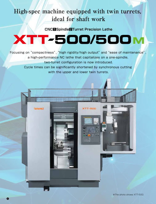
High-spec machine equipped with twin turrets, Realizing versatile cutting with
ideal for shaft work the one-spindle, two-turret
configuration in a compact design
CNC1Spindle2Turret Precision Lathe
In addition to balance cutting, which is possible only with upper and
XTT 500/500 lower twin turrets and high-efficiency simultaneous individual cutting
to substantially shorten cycle times, cutting can be carried out
appropriately for a variety of workpiece forms.
While the machine width is compact at 1,695 mm, it has sufficient
Focusing on“ compactness”,“ high rigidity/high output” and“ ease of maintenance”, internal cutting space to accommodate long workpieces, with a Z-axis
stroke of 450 mm (X-axis stroke of 105 mm).
a high-performance NC lathe that capitalizes on a one-spindle, The highly rigid 8-station turrets allow leeway with the tooling,
two-turret configuration is now introduced. expanding the possibilities.
Cycle times can be significantly shortened by synchronous cutting Left and Right
Balance Cutting Individual Cutting
with the upper and lower twin turrets.
Through synchronous cutting, the Since each turret carries out its own
upper and lower twin turrets play the cutting, cycle times can be shortened
role of a steady rest, suppressing significantly.
deflection of the workpiece and
achieving high accuracy.
Crankshaft Primary sheave Secondary Intermediate Drive pinion
sheave shaft
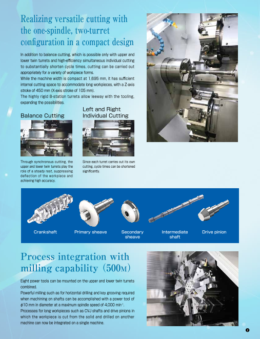
Process integration with
milling capability( 500M)
Eight power tools can be mounted on the upper and lower twin turrets
combined.
Powerful milling such as for horizontal drilling and key grooving required
when machining on shafts can be accomplished with a power tool of
φ10 mm in diameter at a maximum spindle speed of 4,000 min-1.
Processes for long workpieces such as CVJ shafts and drive pinions in
which the workpiece is cut from the solid and drilled on another
※The photo shows XTT-500. machine can now be integrated on a single machine.
Page3
High-spec machine equipped with twin turrets, Realizing versatile cutting with
ideal for shaft work the one-spindle, two-turret
configuration in a compact design
CNC1Spindle2Turret Precision Lathe
In addition to balance cutting, which is possible only with upper and
XTT 500/500 lower twin turrets and high-efficiency simultaneous individual cutting
to substantially shorten cycle times, cutting can be carried out
appropriately for a variety of workpiece forms.
While the machine width is compact at 1,695 mm, it has sufficient
Focusing on“ compactness”,“ high rigidity/high output” and“ ease of maintenance”, internal cutting space to accommodate long workpieces, with a Z-axis
stroke of 450 mm (X-axis stroke of 105 mm).
a high-performance NC lathe that capitalizes on a one-spindle, The highly rigid 8-station turrets allow leeway with the tooling,
two-turret configuration is now introduced. expanding the possibilities.
Cycle times can be significantly shortened by synchronous cutting Left and Right
Balance Cutting Individual Cutting
with the upper and lower twin turrets.
Through synchronous cutting, the Since each turret carries out its own
upper and lower twin turrets play the cutting, cycle times can be shortened
role of a steady rest, suppressing significantly.
deflection of the workpiece and
achieving high accuracy.
Crankshaft Primary sheave Secondary Intermediate Drive pinion
sheave shaft
Process integration with
milling capability( 500M)
Eight power tools can be mounted on the upper and lower twin turrets
combined.
Powerful milling such as for horizontal drilling and key grooving required
when machining on shafts can be accomplished with a power tool of
φ10 mm in diameter at a maximum spindle speed of 4,000 min-1.
Processes for long workpieces such as CVJ shafts and drive pinions in
which the workpiece is cut from the solid and drilled on another
※The photo shows XTT-500. machine can now be integrated on a single machine.
Page4
0.5mm/rev Variety of options for shaft work
The tailstock is self-propelled using high-rigidity hydraulic cylinder drive,
which exerts a strong thrust. The tailstock travel position is detected by
a linear encoder and this is linked to the machining program, helping to
reduce the man hours spent on setup changes.
High-rigidity tailstock
Using servomotor drive, the workpiece steady rest allows the workpiece
support position to be adjusted easily by simply modifying the program,
enabling support for handling multiple workpiece types.
Tailstock specifications
Cutting Cross Sectional Area(t*f) Item Unit Spindle φ100-mm specifications Spindle φ120-mm specifications
2.50mm2/rev Pointed End MT-4 MT-5
Quill O.D. mm φ105
※15/11kW For short-time rating Steady rest that proves Tailstock stroke mm 350(Hydraulic)
effective with long workpieces
Stable cutting with high rigidity/high output (Made by SMW, Model: SLU-X-1) Max. thrust kN 5.5
A high-output 15/11 kW spindle motor is adopted for a high-rigidity spindle with an 8-inch chuck and φ100 mm bearing. Loader can be installed
Furthermore, the X and Z axes use square box-way slides, realizing a robust mechanical structure. Heavy-duty cutting at a low position thanks
capability and high accuracy can be maintained over the long term. to the slant construction
Spindle power characteristic curve
■ Max.4,000min(-1 AC 15/11kW) φ100 ■ Max.3,500min(-1 AC 18.5/15kW) φ120
18 1,333min-1 2,333min-1 20 877min-1 2,047min-1
Power tool power 18.5kW(15min.S3 25% operation area)
characteristic curve 15 15kW(15min.S3 25% operation area)
16
T=143N・m 60min.S3 40% operation area 14.9kW
10 12 60min.S3 40% operation area 15kW
11.2kW
2 8 11kW 12 Cont. rating area 12.1kW Loader hand for shaft work
9 Cont. rating area
(kW) 8.2kW (kW)
6 T=105N・m 8 T=201N・m
T=5.5N・m 6 T=79N・m T=163N・m
(kW)1 4(N・m) T=122N・m
W
P=
1.8
k
2 3 4
0 0 0 0
0 1 2 3 4 0 1 2 3 4 0 1 2 3
Spindle speed(×1,000min-1) Spindle speed(×1,000min-1) Spindle speed(×1,000min-1)
Slide doors for
exceptional ease of
maintenance Equipped with dedicated loader“ ΣiGT500”
Light, compact pendant
operation panel
A large sliding door with an opening of 500 Incorporating the new 3-axis loader “ΣiGT500” with a maximum
mm is provided at the right side of the machine payload of 8 kg (per side) allows stable mass production of heavy
front. workpieces such as shafts, and helps with productivity improvement
The door opens in a one-touch operation, assuring and labor savings.
ample maintenance area. Access to the turrets Adopting a 60° slant bed construction keeps the machine height low
and tailstock is easy, and helps to reduce the and allows a design with a low loader position. This gives easy access
time spent on setup. 500mm to the loader hand and facilitates work such as hand changes.
The loader hand is arranged so that it can move in accordance with Loader transfer capacity
the inclination of the 60° slant bed for easier handling. This avoids Item Unit ΣiGT500
interference inside the machine such as with the steady rest, Optimal workpiece mm
Capacity φ25~φ70 × 400
improves the level of freedom in loading, and results in a further Weight capacity kg 8.0(one side)
With the sub-slide door at the right of the machine open. reduction of cycle times. (Patented technology) axis stroke mm X : 235 Y : 690 Z : Depends on specifications
Machine components such as the tailstock are grouped together, and a large Body
maintenance area can be secured with a one-touch operation. What is more, the pendant operation panel dedicated to the loader Rapid traverse rate m/min X:35 Z:170 Y:125
makes it simple to work while monitoring the position of the loader. Hand Jaw stroke mm 20(one side)
Output
torque
Output
5mm
Output
Page5
0.5mm/rev Variety of options for shaft work
The tailstock is self-propelled using high-rigidity hydraulic cylinder drive,
which exerts a strong thrust. The tailstock travel position is detected by
a linear encoder and this is linked to the machining program, helping to
reduce the man hours spent on setup changes.
High-rigidity tailstock
Using servomotor drive, the workpiece steady rest allows the workpiece
support position to be adjusted easily by simply modifying the program,
enabling support for handling multiple workpiece types.
Tailstock specifications
Cutting Cross Sectional Area(t*f) Item Unit Spindle φ100-mm specifications Spindle φ120-mm specifications
2.50mm2/rev Pointed End MT-4 MT-5
Quill O.D. mm φ105
※15/11kW For short-time rating Steady rest that proves Tailstock stroke mm 350(Hydraulic)
effective with long workpieces
Stable cutting with high rigidity/high output (Made by SMW, Model: SLU-X-1) Max. thrust kN 5.5
A high-output 15/11 kW spindle motor is adopted for a high-rigidity spindle with an 8-inch chuck and φ100 mm bearing. Loader can be installed
Furthermore, the X and Z axes use square box-way slides, realizing a robust mechanical structure. Heavy-duty cutting at a low position thanks
capability and high accuracy can be maintained over the long term. to the slant construction
Spindle power characteristic curve
■ Max.4,000min(-1 AC 15/11kW) φ100 ■ Max.3,500min(-1 AC 18.5/15kW) φ120
18 1,333min-1 2,333min-1 20 877min-1 2,047min-1
Power tool power 18.5kW(15min.S3 25% operation area)
characteristic curve 15 15kW(15min.S3 25% operation area)
16
T=143N・m 60min.S3 40% operation area 14.9kW
10 12 60min.S3 40% operation area 15kW
11.2kW
2 8 11kW 12 Cont. rating area 12.1kW Loader hand for shaft work
9 Cont. rating area
(kW) 8.2kW (kW)
6 T=105N・m 8 T=201N・m
T=5.5N・m 6 T=79N・m T=163N・m
(kW)1 4(N・m) T=122N・m
W
P=
1.8
k
2 3 4
0 0 0 0
0 1 2 3 4 0 1 2 3 4 0 1 2 3
Spindle speed(×1,000min-1) Spindle speed(×1,000min-1) Spindle speed(×1,000min-1)
Slide doors for
exceptional ease of
maintenance Equipped with dedicated loader“ ΣiGT500”
Light, compact pendant
operation panel
A large sliding door with an opening of 500 Incorporating the new 3-axis loader “ΣiGT500” with a maximum
mm is provided at the right side of the machine payload of 8 kg (per side) allows stable mass production of heavy
front. workpieces such as shafts, and helps with productivity improvement
The door opens in a one-touch operation, assuring and labor savings.
ample maintenance area. Access to the turrets Adopting a 60° slant bed construction keeps the machine height low
and tailstock is easy, and helps to reduce the and allows a design with a low loader position. This gives easy access
time spent on setup. 500mm to the loader hand and facilitates work such as hand changes.
The loader hand is arranged so that it can move in accordance with Loader transfer capacity
the inclination of the 60° slant bed for easier handling. This avoids Item Unit ΣiGT500
interference inside the machine such as with the steady rest, Optimal workpiece mm
Capacity φ25~φ70 × 400
improves the level of freedom in loading, and results in a further Weight capacity kg 8.0(one side)
With the sub-slide door at the right of the machine open. reduction of cycle times. (Patented technology) axis stroke mm X : 235 Y : 690 Z : Depends on specifications
Machine components such as the tailstock are grouped together, and a large Body
maintenance area can be secured with a one-touch operation. What is more, the pendant operation panel dedicated to the loader Rapid traverse rate m/min X:35 Z:170 Y:125
makes it simple to work while monitoring the position of the loader. Hand Jaw stroke mm 20(one side)
Output
torque
Output
5mm
Output
Page6
Tooling system Turret Interference Stroke-Related Drawing
O.D./Face/ O.D./Face/
Grooving tool□25 Grooving tool□25
Clamp block Clamp block Distance between 802
□25 centers : 200
193 457 70
300
5
O.D./Face/ O.D./Face/ □2 450st
Grooving tool□25 Grooving tool□25
47 104 42
Turning holder Turning holder
O.D./Face/Grooving tool□25
φ32 □25 (108)
Tap Tap holder O.D.nozzle Tap Tap holder O.D.nozzle
126 350st 25
Round hole bush Round hole bush φ427
φ25 φ25
φ20 φ20 Offset holder A2-6 ZA6-8-0-04 MT-4
Boring bar φ16 Nose (MATSUMOTO)
φ12 Boring bar φ16 φ25
4
Maxφ32 0
φ10 Maxφ32 φ12
φ10 φ2
1
φ8 φ32 boring holder φ8 φ32 boring holder A2-8 N-10
Blank Blank iameterφ70 Nose (KITAGAWA) MT-5
Steady rest gr
ipping d
Center Center OP:Tailstock
(Option) Distance between 25
straight Drill Drill chuck arbor Drill Drill chuck arbor
huck JT1-φ32 8 station turret straight centers : 200 (28) (Self-propelling)
drill c chuck JT1-φ25 8 station turret □25 (134)
JT2-φ32 drill JT2-φ25
05 OP:Center rest unit
Drill socket Drill socket φ1 60 115 46
MT-2 MT-2 ete
r
Taper drill Drill Taper drill Drill dia
m
sleeve sleeve ill
Qu 193 450st
MT-1×MT-2 MT-1×MT-2 φ25
3 0
U drill Round hole bush U drill Round hole bush 221 429 70
φ4
1
Maxφ32 φ25 φ32 U drill holder Maxφ32 φ25 φ32 U drill holder 2
φ20 φ20 φ3
Straight drill
! Attention XTT-500
Endmill
M Maxφ13 Collet chuck
B A AR20-φD Face milling holder
・A power tool holder or offset holder can be mounted on station A. Tap
MaxM10
・A turning holder, boring holder or U drill holder can be
mounted on station B.
Side milling holder
35
196 413 110
Floor Space Drawing 320 45
φ1 40
Distance between 342 31
centers : 200 50
□2
5
47 107 42
Standard Loader Specifications
40
MAX.40 13
B A
450st
φ445 127 350st (108)
Max.turning dia. 123 350st 25
450st
N-08 □25 MT-4
φ21
0 (KITAGAWA)
Distance between A2-6
centers : 210 Nose
meterφ70
Steady rest
gripping dia
φ210
2,825 (Option) 5
rφ10 Distance between 450st
mete φ32
centers : 210 B A
Quill
dia Distance between
centers : 200 OP:Tailstoc(k Self-propelling)
φ445
Max.turning dia. φ145 OP:Center rest unit
Offset holder
7 45
35
45 5
□2
2 20
90 3
200 1,695 290(105) 480 200 1,695 290(105) 475
2,185(2,000) 1,830 900 930 2,185(2,000) 590.4 1,830 950 930 ! Attention
Chip conveyor
draw-out dimensions. Chip conveyor
draw-out dimensions. ・A power tool holder or offset holder can be mounted on station A.
・A turning holder, boring holder or U drill holder can be mounted on station B.
Data in parentheses is for XTT-500. Uni(t mm) ・Set the tooling with due care, even if within the turret’s swing diameter. The tools may interfere with covers or the tailstock inside the machine. Uni(t mm)
1,850
2,854
1,085
695
B A
1,850
737.5
2,070
1,735
2,400
2,910
3,020.7
1,085
700
1,850
45
290
B A φ210
MAX.40
B A φ32
105st
105st φ10 105st 105st
φ36
145 30 30 160 150 30 30 150
30
B A
B A
B A
285 150
t 3
0 295
105
s 8 30
64. 16
0
5 t28 105
s
30 t
80 295 1
05s
150 st B A
30 1
05
160
B A
φ250
B A
Page7
Tooling system Turret Interference Stroke-Related Drawing
O.D./Face/ O.D./Face/
Grooving tool□25 Grooving tool□25
Clamp block Clamp block Distance between 802
□25 centers : 200
193 457 70
300
5
O.D./Face/ O.D./Face/ □2 450st
Grooving tool□25 Grooving tool□25
47 104 42
Turning holder Turning holder
O.D./Face/Grooving tool□25
φ32 □25 (108)
Tap Tap holder O.D.nozzle Tap Tap holder O.D.nozzle
126 350st 25
Round hole bush Round hole bush φ427
φ25 φ25
φ20 φ20 Offset holder A2-6 ZA6-8-0-04 MT-4
Boring bar φ16 Nose (MATSUMOTO)
φ12 Boring bar φ16 φ25
4
Maxφ32 0
φ10 Maxφ32 φ12
φ10 φ2
1
φ8 φ32 boring holder φ8 φ32 boring holder A2-8 N-10
Blank Blank iameterφ70 Nose (KITAGAWA) MT-5
Steady rest gr
ipping d
Center Center OP:Tailstock
(Option) Distance between 25
straight Drill Drill chuck arbor Drill Drill chuck arbor
huck JT1-φ32 8 station turret straight centers : 200 (28) (Self-propelling)
drill c chuck JT1-φ25 8 station turret □25 (134)
JT2-φ32 drill JT2-φ25
05 OP:Center rest unit
Drill socket Drill socket φ1 60 115 46
MT-2 MT-2 ete
r
Taper drill Drill Taper drill Drill dia
m
sleeve sleeve ill
Qu 193 450st
MT-1×MT-2 MT-1×MT-2 φ25
3 0
U drill Round hole bush U drill Round hole bush 221 429 70
φ4
1
Maxφ32 φ25 φ32 U drill holder Maxφ32 φ25 φ32 U drill holder 2
φ20 φ20 φ3
Straight drill
! Attention XTT-500
Endmill
M Maxφ13 Collet chuck
B A AR20-φD Face milling holder
・A power tool holder or offset holder can be mounted on station A. Tap
MaxM10
・A turning holder, boring holder or U drill holder can be
mounted on station B.
Side milling holder
35
196 413 110
Floor Space Drawing 320 45
φ1 40
Distance between 342 31
centers : 200 50
□2
5
47 107 42
Standard Loader Specifications
40
MAX.40 13
B A
450st
φ445 127 350st (108)
Max.turning dia. 123 350st 25
450st
N-08 □25 MT-4
φ21
0 (KITAGAWA)
Distance between A2-6
centers : 210 Nose
meterφ70
Steady rest
gripping dia
φ210
2,825 (Option) 5
rφ10 Distance between 450st
mete φ32
centers : 210 B A
Quill
dia Distance between
centers : 200 OP:Tailstoc(k Self-propelling)
φ445
Max.turning dia. φ145 OP:Center rest unit
Offset holder
7 45
35
45 5
□2
2 20
90 3
200 1,695 290(105) 480 200 1,695 290(105) 475
2,185(2,000) 1,830 900 930 2,185(2,000) 590.4 1,830 950 930 ! Attention
Chip conveyor
draw-out dimensions. Chip conveyor
draw-out dimensions. ・A power tool holder or offset holder can be mounted on station A.
・A turning holder, boring holder or U drill holder can be mounted on station B.
Data in parentheses is for XTT-500. Uni(t mm) ・Set the tooling with due care, even if within the turret’s swing diameter. The tools may interfere with covers or the tailstock inside the machine. Uni(t mm)
1,850
2,854
1,085
695
B A
1,850
737.5
2,070
1,735
2,400
2,910
3,020.7
1,085
700
1,850
45
290
B A φ210
MAX.40
B A φ32
105st
105st φ10 105st 105st
φ36
145 30 30 160 150 30 30 150
30
B A
B A
B A
285 150
t 3
0 295
105
s 8 30
64. 16
0
5 t28 105
s
30 t
80 295 1
05s
150 st B A
30 1
05
160
B A
φ250
B A
Page8
CNC1Spindle2Turret Controller Specifications
Precision Lathe Item XTT-500 XTT-500M
TAKAMAZ & FANUC 0i-TF CNC1Spindle2Turret
Controlled axes 4 axes(X1, X2, Z1, Z2) 5 axes(X1, Z1, C, X2, Z2)
Simultaneously controllable axes Simultaneous 2 axes(× 2)Simultaneous 3 axes (× 2) Precision Lathe
Machine Specifications Least input increment 0.001mm (X in diameter)
Least command increment X : 0.0005mm Z : 0.001mm
Item Unit XTT-500 XTT-500M Auxiliary function M-code 3 digit
Max. turning diameter mm φ210 Spindle function S-code 4 digit
Max. turning length mm 450 400 Tool function T-code 4 digit
Tape code EIA(RS232C)/ISO(840)automatic recognition
Max. bar diameter mm φ42, φ51(φ65) φ42, φ51 Cutting feedrate 1~5,000mm/min
Chuck size inch Collet, 8(10) Collet, 8 Command system Incremental/Absolute
Spindle nose JIS A2-6(A2-8) A2-6 Linear interpolation G01
Spindle bearing I.D. mm φ100(φ120) φ100 Circular interpolation G02, G03
Through-hole on spindle mm φ61(φ80) φ61 Cutting feedrate override 0~150%
Rapid traverse override F0, 100%
Spindle speed min -1 Max.4,000(3,500) Max.4,000 Program file name 32 characters
Type 8-station turret×2 Backlash compensation 0~9,999μm
Tool shank mm □25 Program memory capacity 1Mbyte (2,560m)(Dual systems total)
Boring holder I.D. mm φ32 Tool offsets 128 sets (Dual systems total)
Registered programs
Max. stroke mm X:105 Z:450 800 pcs. (Dual systems total)
Tool geometry/Wear offset Standard
Rapid traverse rate m/min X:18 Z:24 Canned cycle G90, G92, G94
Tool storage capacity pcs. - 4(one side) Radius designation on arc Standard
Rotation speed min -1 - Max.4,000 Tool offset measurement input Standard
Drill mm - φ10 Background editing Standard
Direct drawing dimension programming Standard
Capacity Endmill mm - φ10 Custom macro Standard
Tap mm - M4~M8 Custom macro common variables #100~#199, #500~#999
Rapid traverse rate deg./min - 18,000 Pattern data input Standard
C-axis
C-axis motor kW - AC 0.5 Nose R compensation G40, G41, G42
Inch/Metric conversion
Spindle motor kW AC15/11(18.5/15) AC15/11 G20/G21
Programmable data input G10
Feed motor kW X:AC1.2 Z:AC1.8 Run hour/Parts count display Standard
Coolant motor kW AC 0.4×2 Extended part program editing Standard
Hydraulic motor kW AC1.5 Multiple repetitive cycle G70~G76
Power tools motor kW - AC1.8 Multiple repetitive cycle Ⅱ Pocket-shaped
Canned drilling cycle Standard
L×W×H mm
Size 1,695×1,830×1,850 Constant surface speed control G96, G97
Machine weight kg 4,600 4,800 Continuous thread cutting G32
Total electric capacity KVA 26 28 Variable lead thread cutting G34
( ):Option Thread cutting retract Standard
Clock function Standard
Standard Accessories Help function Standard
Alarm history display 50 pcs.
□Clamp block ……………………… 16sets □Power tools drive uni(t 500M) … 1set Self-diagnosis function Standard
□Coolant block(For reverse cutting tools)… 16sets □Thread cutting unit Sub-program call Up to 10 loops
□Hydraulic chucks(8 inch・Solid)… 1set (Including constant surface speed control)… 1set Decimal point input Standard
□Hydraulic chucking cylinde(r Solid)… 1set □Coolant uni(t 170 lit.)………… 1set 2nd reference point return G30
Work coordinate system setting
□Hydraulic unit ……………………… 1set □Work light ………………………… 1set G50, G54~G59
Rigid tapping - Standard
□Chuck clamp detector …………… 1set □Service tool kit ………………… 1set Polar coordinate interpolation - Standard
□Spindle indexing device(C-axis/500M)… 1set □TAKAMAZ instruction manual …… 1set Cylindrical interpolation - Standard
Stored stroke check 1 Standard
Optional Accessories Stored stroke check 2,3 Standard
Input/Output interface USB Flash Memory, Memory card, Ethernet
□Tool holders □Power tools(500M) Alarm message Standard
□Collet chucks □Rear chip conveyor Graphic display Standard
□Hydraulic chucks (Floor type/Spiral type) Conversational programming with graphic function Standard
Abnormal load detection Standard
□Alloyed Clamp Holder for vibrations suppression □Front air blower Balance cut G68, G69
□Special spindle speed(3,500min-1) □Rear coolant unit Manual handle trace Standard
□Center rest unit □Signal light(1-Tier/2-Tiers/3-Tiers) Automatic data backup Max. 3
□Storage-type work rest device □Automatic power shut-off device Automatic screen deletion function Standard
□TAKAMAZ loader system □Automatic door system(Auto door/Shutter) TAKAMAZ management support function Work/Tool counter, Tool load monitor, Others
TAKAMAZ maintenance functions Standard
□Spindle indexing device(Electrical/Mechanical) □Special color FANUC set of manuals DVD-ROM
□Tailstock □Others※
※For more information on attachments,consult our sales representative. Optional Specifications
Input/Output interface RS232C
Tool life management
Multiple M codes in one block Max. 3
Spindle orientation 1 set/6 sets
Dynamic graphic display
FANUC instruction manual Bound
TAKAMATSU MACHINERY CO., LTD. TAKAMAZ MACHINERY MEXICO, S.A.DE C.V.
■HEAD OFFICE & PLANT AVENIDA DE LOS INDUSTRIALES 522, LOCAL 4, INDUSTRIAL JULIAN DE OBREGON, 37290 LEON,
1-8 ASAHIGAOKA HAKUSAN-CITY ISHIKAWA JAPAN. 924-8558 TEL +81-(0)76-207-6155 FAX +81-(0)76-274-1418 GUANAJUATO MEXICO
■ASAHI PLANT TEL +52-477-784-0468
4-13 ASAHIGAOKA HAKUSAN-CITY ISHIKAWA JAPAN. 924-0004 TEL +81-(0)76-274-0123 FAX +81-(0)76-274-8530 TAKAMATSU MACHINERY VIETNAM CO., LTD
TAKAMATSU MACHINERY U.S.A., INC. NO.76 M HOANG QUOC VIET, PHU MY WARD, DISTRICT 7, HO CHI MINH CITY, VIETNAM
■CHICAGO HEAD OFFICE TEL +84-(0)28-3620-5671 FAX +84-(0)28-3620-5673
1280 LANDMEIER ROAD ELK GROVE VILLAGE, IL 60007 USA TEL +1-(0)847-981-8577 FAX +1-(0)847-981-8599
TAKAMAZ MACHINERY EUROPE GmbH
IM HÜLSENFELD 19, 40721 HILDEN, GERMANY TEL +49-(0)2103-789-4882 FAX +49-(0)2103-789-4883
TAKAMAZ MACHINERY( HANGZHOU) CO., LTD.
■HANGZHOU HEAD OFFICE
NO.6800, JIANGDONG 3RD ROAD, JIANGDONG INDUSTRIAL PARK, XIAOSHAN, HANGZHOU, ZHEJIANG, CHINA
TEL +86-(0)571-8287-9709 FAX +86-(0)571-8215-3732 Precautions Related to Foreign Exchange and Foreign Trade Control Laws
TAKAMATSU MACHINERY( THAILAND) CO., LTD. This product (machine and ancillary equipment) may fall under the category of controlled
goods by the foreign exchange and foreign trade control laws.
■BANGKOK HEAD OFFICE As such, the exportation must be authorized by the Japanese government as stipulated in the laws
888/59 MOO 9, TAMBOL BANGPLA, AMPHUR BANGPLEE, SAMUTPRAKARN PROVINCE, THAILAND This product is manufactured in accordance with the regulations and standards that prevail in the
TEL +66-(0)2-136-7831 FAX +66-(0)2-136-7834 country or region of destination.
PT. TAKAMAZ INDONESIA The user must not export, sell, or relocate the product, to anycountry with different regulations or standards.
JL. FESTIVAL BOULEVARD BLOK AA 11 NO.30,31 GRAND WISATA TAMBUN, BEKASI 17510
TEL +62-(0)21-8261-6431 FAX +62-(0)21-8261-6430
23.08.1B(O)
Motors Power tools Tool post Spindle Capacity