INSTALLATION AND MAINTENANCE MANUAL
Revised May 2020
AIRSWEEP® MODELS:
VA-06
VA-12
VA-51
VA-06-316-TRI-TRI
VA-12-316-TRI-TRI
Straight Shooter
860-928-6551 19 S. Main Street
Brooklyn, CT 06234
860-928-9450
sales@controlconceptsusa.com controlconceptsusa.com
Table of Contents
Page(s)
Typical AirSweep System Components ........................................................................................................................................ 2
AirSweep Installation Pages 3-18
AirSweep Installation Notes ....................................................................................................................................................... 3-4
AirSweep Models
VA-51 AirSweep – Assembly, Repair Kit Components .......................................................................................................... 5
Specification Drawings .................................................................................................................................................. 6
Mounting Installation Instructions ................................................................................................................................. 7
VA-12 AirSweep – Assembly, Repair Kit Components .......................................................................................................... 8
Specification Drawings .................................................................................................................................................. 9
Mounting Installation Instructions ............................................................................................................................... 10
VA-06 AirSweep – Assembly, Repair Kit Components ........................................................................................................ 11
Specification Drawings ................................................................................................................................................. 12
Mounting Installation Instructions ............................................................................................................................... 13
Tri-Clamp AirSweep (VA-06-TRI-TRI and VA-12-TRI-TRI) – Assembly, Repair Kit Components ......................................... 14
Specification Drawings ................................................................................................................................................. 15
Mounting Installation Instructions .............................................................................................................................. 16
Straight Shooter AirSweep – Assembly, Repair Kit Components ...................................................................................... 17
Mounting Installation Instructions .............................................................................................................................. 18
AirSweep Maintenance Requirements ....................................................................................................................................... 19
AirSweep System Components Pages 20 – 65
Solenoid Valves
SV-75 3/4" Diaphragm Valve ................................................................................................................................. 21 & 23-25
SV-150 1-1/2" Diaphragm Valve .................................................................................................................................... 22-25
DV1251 1-1/2" High Flow, Pulse-type Diaphragm Valve .............................................................................................. 26-32
DV06 3/4" High Flow, Pulse-type Valve .......................................................................................................................... 33-35
8262 Series Pilot Valves (Remote Pilot-Operated Diaphragm Valves)............................................................................... 36
MCA45T 1-1/2" High Flow, Pulse-type Diaphragm Valve .............................................................................................. 37-38
RCA3DM Pilot Valve Coil Kit for RCAC20S ........................................................................................................................... 39
RCAC20ST High Flow, Remote Pilot-operated, Pulse-type Diaphragm Valve ................................................................... 40
VXM Series Stainless Steel Diaphragm Valves ................................................................................................................... 41
Troubleshooting Diaphragm Valves ...................................................................................................................................... 42-43
Flexible Hose Assemblies ...................................................................................................................................................... 44-45
Air Receivers – 30, 60, 80, 120 Gallon ASME models ......................................................................................................... 46-47
Air Receiver Tank Components ............................................................................................................................................ 48
Drain Trap .............................................................................................................................................................................. 48
Check Valves ................................................................................................................................................................................. 49
Particulate Filters ................................................................................................................................................................... 50-51
F901G Series ......................................................................................................................................................................... 50
F329-08W .............................................................................................................................................................................. 51
Pressure Relief Valve ............................................................................................................................................................... 52-56
Ball Valves ..................................................................................................................................................................................... 57
High-flow Regulators .............................................................................................................................................................. 58-59
CBO-Series System Timer/Sequence Controllers
Overview ................................................................................................................................................................................ 60
1-4 Output ....................................................................................................................................................................... 61-62
10 Output ........................................................................................................................................................................ 63-64
Control Box Enclosures .................................................................................................................................................. 65-66
1-860-928-6551 • Sales@ControlConceptsUSA.com • www.AirSweepSystems.com 1
Page3
Typical AirSweep System
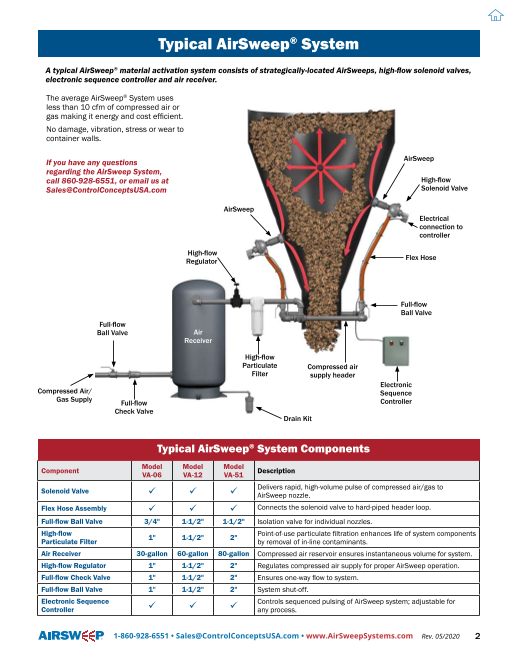
Typical AirSweep® System
A typical AirSweep® material activation system consists of strategically-located AirSweeps, high-flow solenoid valves,
electronic sequence controller and air receiver.
The average AirSweep® System uses
less than 10 cfm of compressed air or
gas making it energy and cost efficient.
No damage, vibration, stress or wear to
container walls.
If you have any questions AirSweep
regarding the AirSweep System,
call 860-928-6551, or email us at High-flow
Sales@ControlConceptsUSA.com Solenoid Valve
AirSweep
Electrical
connection to
controller
High-flow
Regulator Flex Hose
Full-flow
Ball Valve
Full-flow
Ball Valve Air
Receiver
High-flow
Particulate Compressed air
Filter supply header
Electronic
Compressed Air/ Sequence
Gas Supply Full-flow Controller
Check Valve
Drain Kit
Typical AirSweep® System Components
Component Model Model Model VA-06 VA-12 VA-51 Description
Solenoid Valve ü ü ü Delivers rapid, high-volume pulse of compressed air/gas to AirSweep nozzle.
Flex Hose Assembly ü ü ü Connects the solenoid valve to hard-piped header loop.
Full-flow Ball Valve 3/4" 1-1/2" 1-1/2" Isolation valve for individual nozzles.
High-flow 1" 1-1/2" 2" Point-of-use particulate filtration enhances life of system components Particulate Filter by removal of in-line contaminants.
Air Receiver 30-gallon 60-gallon 80-gallon Compressed air reservoir ensures instantaneous volume for system.
High-flow Regulator 1" 1-1/2" 2" Regulates compressed air supply for proper AirSweep operation.
Full-flow Check Valve 1" 1-1/2" 2" Ensures one-way flow to system.
Full-flow Ball Valve 1" 1-1/2" 2" System shut-off.
Electronic Sequence Controls sequenced pulsing of AirSweep system; adjustable for
Controller ü ü ü any process.
1-860-928-6551 • Sales@ControlConceptsUSA.com • www.AirSweepSystems.com Rev. 05/2020 2
Page4
AIRSWEEP INSTALLATION NOTES
AIRSWEEP® INSTALLATION NOTES
Consult installation drawing (if provided) for proper AirSweep location. It is important to adhere to the
recommended locations as the type, number and location of AirSweeps have been selected for thorough
"sweep" coverage of problem surfaces in the vessel or chute.
It is usually not necessary to clean out or empty the vessel before installing the AirSweeps. Even if a
"crust" of material has built up inside the vessel, the air blasts will generally cut it away from the vessel
wall over a period of time. Consequently, the "crust" sometimes breaks away in chunks, and it is possible
that these chunks will clog the discharge. If clogging occurs, the vessel should be cleaned manually prior
to start up.
CAUTION: NEVER ENTER A VESSEL WHILE AIRSWEEPS ARE OPERATING
If the material in the vessel has a tendency to run out of a hole cut in the vessel wall, the level of material
in the vessel should be dropped below the AirSweep location before cutting the holes in the
vessel wall.
When welding, a continuous bead should be used to fasten the mounting to the vessel wall on steel
vessels. Anchor bolts can be set in concrete vessel walls to coincide with the bolt hole pattern of the
mounting plate or flange so that the mounting can be bolted to the wall.
Alert: Welding procedure must be done properly to avoid warping of Mounting Coupling.
Welding should be done in accordance with the American Welding Society (AWS) standards as supported by
ASME (American Society of Mechanical Engineers).
PIPING INSTALLATION
It is suggested that you follow the piping schematic that is a part of this instruction manual. (See pg 2)
Never use smaller pipe size fittings or valves than the ones shown.
It is important that the header be installed below the level of the AirSweeps so that any condensation
that may form in the lines will not drain into the AirSweeps. If the header must be installed above the
level of installed AirSweeps, the feed lines for the individual AirSweeps must be taken off the top of the
header (rather than the bottom) to minimize condensation drainage into the AirSweeps and solenoids.
A full flow gate or ball valve is recommended as it allows one AirSweep to be taken out of service without
shutting down the entire system.
Using flexible air hose in lieu of rigid piping from the header to the solenoids is recommended for ease of
installation and for easy removal of the AirSweep when service is required.
NOTE: USING SUITABLE SAFEGUARDS – Always blow out all air supply lines thoroughly before final hook
up to solenoids. Dirt in supply lines may cause the solenoid valves to malfunction.
When operating properly, with material in the vessel, the AirSweeps are almost silent. If an AirSweep
begins to chatter, vibrate or "machine gun", it is generally caused by a malfunctioning solenoid valve,
often due to dirt. If this occurs, SHUT OFF ELECTRIC & AIR SUPPLY and DISCHARGE AIR in system, then
clean solenoid thoroughly (see Troubleshooting on page 42).
1-860-928-6551 • Sales@ControlConceptsUSA.com • www.AirSweepSystems.com Rev. 05/2020 3
AIRSWEEP® INSTALLATION NOTES (continued)
AIR USAGE NOTE
It is important to note that the lower limit of the interval timer is governed by how fast the air receiver can
recover its air loss from the preceding AirSweep burst. If there is some doubt, a gauge should be installed
on the air receiver tank or header. For example, if the gauge initially reads 95 psi when the receiver is
fully pressurized, it should not drop below 80 psi for one burst if the receiver has been properly sized.
The instant the receiver again recovers the 95 psi after one AirSweep is fired, it is then ready for another
firing. If the gauge never indicates the original pressure, the AirSweeps are firing faster than the air
supply can recover.
GENERAL NOTES & SUMMARY:
• For personal safety, the entire electrical system must be properly grounded.
• D istance between air receiver and header has no limit, as long as 2" pipe (1" for VA-06) and fittings
are used throughout.
• S lope header toward receiver 1/4" per ft. for moisture drainage. Whenever possible, locate header
below AirSweeps.
• A lways tap feed lines off top of header (even if header is above AirSweeps) to prevent moisture
drainage into solenoid valves and AirSweeps.
• Never use pipe or fittings smaller than sizes indicated.
• Use location arrangement drawing (if provided) for AirSweep location.
• Whenever possible, complete header loop around the hopper.
• M anual isolation valves (optional) must be gate valves or comparable full orifice valves, to not induce
flow restriction in system.
• If vessel is outdoors, air receiver and filter should be located indoors whenever possible.
• Use of a check valve is recommended if plant air pressure varies more than 10 psi.
• A ir Supply: VA-12 & VA-51 – 80 minimum to 100 maximum psig
VA-06 – 40 minimum to 60 maximum psig
• IMPORTANT! Solenoid valves must be located at AirSweep air inlets and not any distance upstream.
• P urge all lines and unions before connecting to solenoid valves. Particulate in lines may result in
solenoid valve malfunction and excessive maintenance.
• Use PTFE tape on pipe joints rather than pipe dope, to avoid fouling of solenoid valves.
1-860-928-6551 • Sales@ControlConceptsUSA.com • www.AirSweepSystems.com Rev. 05/2020 4
VA-51-NPT-TB
2" AirSweep® Assembly and Mounting Options
Lock Nut
Mounting Options
Jam Nut
Elastic Stop Nut
Compression Washer
Mounting Coupling
Compression Spring (Weld to vessel) Mounting Flange
(Bolt to vessel)
Part Number per Material of Construction
Spring Guide
Qty. Description Carbon Steel 304 Stainless 316 Stainless Steel Steel
1 Valve Body VB-51-CS VB-51-SS VB-51-316
*1 Valve Stem VCW-51-CS VCW-51-SS VCW-51-316
*1 Spring Guide SG-51-CS SG-51-SS SG-51-316
Valve Body
*1 Compression Spring CS-1251-316 CS-1251-316 CS-1251-316
*1 Compression Washer CW-1251-316 CW-1251-316 CW-1251-316
*1 Elastic Stop Nut ESN-1251-CS ESN-1251-SS ESN-1251-SS
*1 Jam Nut JN-1251-CS JN-1251-SS JN-1251-SS
Valve Stem (Piston) 1 Mounting Flange MF-51-CS-T MF-51-SS-T MF-51-316-T
1 Mounting Coupling MC-51-CS-T MC-51-SS-T MC-51-316-T
1 Lock Nut LN-51-CS LN-51-SS LN-51-316
* This part is included in the Rebuild Kit.
Model VA-51 Rebuild Kit
AirSweep Nozzle Rebuild Kit contains 1 each: When ordering, specify Model VA-51
• valve stem material of construction. Rebuild Kit
• spring guide Carbon Steel RK-51-CS
• compression washer
• compression spring 304 Stainless Steel RK-51-SS
• elastic stop nut
• jam nut 316 Stainless Steel RK-51-316
Recommended service interval of internal parts:
Approximately 1 million cycles.* * Typical service interval under standard operating
Maintenance recommended: conditions. Some environments, materials and processes may result in a shorter useful service interval.
Replacement of internal parts.
1-860-928-6551 • Sales@ControlConceptsUSA.com • www.AirSweepSystems.com Rev. 05/2020 5
Construction
Material
Page7
VA-51 Specification Drawings
VA-51-NPT-TB
2" AirSweep® Specification Drawings
Specifications subject to change without notice.
VA-51-NPT-TB Assembly
Lock Nut
2 3/8-12 UN
THREAD 1 1/2 NPT FEMALE
THREAD 1/2"
(12.70 mm)
2 3/8-12 UN
THREAD
2 15/64" 3 1/4" (82.60 mm)
(56.64 mm )
5/16" 5 1/8" (130.18 mm)
(7.94 mm)
7" (177.80 mm)
Mounting Options
Mounting Coupling Mounting Flange
(Weld to vessel) (Bolt to vessel)
7/8" 5/8" (15.88 mm)
(22.23 mm) 2 3/8-12 UN
2 3/8-12 UN THREAD
THREAD
3 1/2"
(88.39 mm)
11/16" (17.46 mm) 5 15/16"
1" HOLES 4 PLACES (150.80 mm)
(25.40 mm) 4 1/2" (114.30 mm) BHC
Standard materials of construction include:
• Carbon Steel
• 304 Stainless Steel
• 316 Stainless Steel
Other materials available upon request.
VA-51 Performance (per unit)*
Material Activation Compressed Air/Gas
Diameter Consumption (per pulse)
6 feet 2.18 scf @ 80 psi
(1.83 m) (0.062 m3 @ 5.52 bar)
8 feet 2.99 scf @ 100 psi
(2.44 m) (0.085 m3 @ 6.89 bar)
* Average in 75 lbs/ft3 material; 250 millisecond pulse.
1-860-928-6551 • Sales@ControlConceptsUSA.com • www.AirSweepSystems.com Rev. 05/2020 6
Page8
VA-51 Mounting Installation
VA-51-NPT-TB
Mounting Installation
MC-51 Mounting Coupling Installation (Weld to vessel)
MC-51 Mounting Coupling Installation
1. Cut hole in vessel wall. Recommended hole
1-1/2" NPT size is approximately 1/8" (3.175 mm) greater
Pipe Nipple than diameter of coupling to allow coupling to
(P/N CN-51)
Connect directly Threaded Mounting Coupling Vessel pass through curved wall. The MC-51 mounting
to outlet port of Align flush with inside of (Inside Wall) coupling is 3-1/2" (88.9 mm) dia., therefore the
solenoid valve. vessel wall. recommended hole size is 3-5/8" (92.075 mm).
2. A lign coupling flush with inside of vessel wall and
weld continuous bead to exterior of wall.*
3. Apply anti-seize compound to front threaded section
AirSweep
Piston Head of AirSweep. Thread AirSweep into position so the
should protrude front of the body is aligned with the front of
fully into vessel. coupling. This will properly position the piston
head within the vessel.
VA-51 AirSweep 2 3/8-12 UN 4. After the position of the AirSweep is determined Body aligned FLUSH with Thread to be correct, tighten the lock collar against the inside of vessel wall.
Lock Nut coupling to keep the AirSweep in position.
Note: On sharply curved bin walls, the body of
AirSweep will extend slightly into the vessel at
the top and bottom (12:00 & 6:00 positions),
and should be flush at sides (3:00 & 9:00
positions).
• F or maximum effectiveness, connection distance
between AirSweep and solenoid valve should be as
short as possible. Use only the supplied connecting
* Welding procedure must be done properly to avoid warping of Mounting Coupling. nipple with no additional elbows or pipe, if possible.
Welding should be done in accordance with the American Welding Society (AWS)
standards as supported by ASME (American Society of Mechanical Engineers).
MF-51 Mounting Flange Installation (Bolt to vessel)
MF-51 Mounting Flange Installation
1. Position flange on wall surface. Mark hole for
Vessel AirSweep. Mark bolt circle layout.
(Inside Wall)
Mounting Flange 2. Drill or cut hole for AirSweep and bolt holes. The
hole size should be sufficient diameter to allow
VA-51 AirSweep AirSweep to pass through wall.
Body aligned 2 3/8-12 UN
FLUSH with inside Thread 3. Fasten flange to wall by bolting.
of vessel wall. 4. Apply anti-seize compound to front threaded section
of AirSweep. Thread the AirSweep into position so
that the front of the AirSweep body is aligned with
AirSweep
Piston Head the inside wall of vessel. This will properly position
piston head within the vessel.
5. A fter the AirSweep is correctly positioned, tighten
lock nut against flange to keep AirSweep in position.
Burn or cut hole
Lock Nut
1-1/2" NPT
Pipe Nipple
(P/N CN-51)
Connect directly
to outlet port of
solenoid valve.
1-860-928-6551 • Sales@ControlConceptsUSA.com • www.AirSweepSystems.com Rev. 05/2020 7
VA-12-NPT-TB
1-1/2" AirSweep® Assembly and Mounting Options
Lock Nut
Mounting Options
Jam Nut
Elastic Stop Nut
Compression Washer
Mounting Coupling Mounting Flange
(Weld to vessel) (Bolt to vessel)
Compression Spring
Part Number per Material of Construction
Spring Guide Qty. Description Carbon Steel
304 Stainless 316 Stainless
Steel Steel
1 Valve Body VB-12-CS VB-12-SS VB-12-316
*1 Valve Stem VCW-12-CS VCW-12-SS VCW-12-316
*1 Spring Guide SG-12-CS SG-12-SS SG-12-316
*1 Compression Spring CS-1251-316 CS-1251-316 CS-1251-316
Valve Body *1 Compression Washer CW-1251-316 CW-1251-316 CW-1251-316
*1 Elastic Stop Nut ESN-1251-CS ESN-1251-SS ESN-1251-SS
*1 Jam Nut JN-1251-CS JN-1251-SS JN-1251-SS
1 Mounting Flange MF-12-CS-T MF-12-SS-T MF-12-316-T
Valve Stem (Piston) 1 Mounting Coupling MC-12-CS MC-12-SS MC-12-316
1 Lock Nut LN-12-CS LN-12-SS LN-12-316
* This part is included in the Rebuild Kit.
Model VA-12 Rebuild Kit
AirSweep Nozzle Rebuild Kit contains 1 each: When ordering, specify Model VA-12
• valve stem material of construction. Rebuild Kit
• spring guide Carbon Steel RK-12-CS
• compression washer
• compression spring 304 Stainless Steel RK-12-SS
• elastic stop nut
• jam nut 316 Stainless Steel RK-12-316
Recommended service interval of internal parts:
Approximately 1 million cycles.* * Typical service interval under standard operating
Maintenance recommended: conditions. Some environments, materials and processes may result in a shorter useful service interval.
Replacement of internal parts.
1-860-928-6551 • Sales@ControlConceptsUSA.com • www.AirSweepSystems.com Rev. 05/2020 8
Construction
Material
Page10
VA-12 Specification Drawings
VA-12-NPT-TB
1-1/2" AirSweep® Specification Drawings
VA-12-NPT-TB Specifications subject to change without notice.
1 7/8-12 UN 1 1/2 NPT
THREAD THREAD Lock Nut
1/2"
(12.70 mm)
1 3/4" 1 7/8-12 UN
(43.94 mm) THREAD
2 3/4"
(69.85 mm)
5/16"
(7.94 mm)
5 1/8"
(130.18 mm)
6 3/4"
(171.45 mm)
Mounting Options
Mounting Coupling Mounting Flange
(Weld to vessel) (Bolt to vessel)
5/8"
(15.88 mm)
7/8" 1 7/8-12 UN
(22.23 mm)
THREAD
1 7/8-12 UN
THREAD
3"
(75.95 mm)
3/8" (9.53 mm) 4 1/2"
1" HOLES 4 PLACES (114.30 mm)
Standard materials of construction include: (25.40 mm) 3 1/2" (88.90 mm) BHC
• Carbon Steel
• 304 Stainless Steel
• 316 Stainless Steel
Other materials available upon request.
VA-12 Performance (per unit)*
Material Activation Compressed Air/Gas
Diameter Consumption (per pulse)
4 feet 1.9 scf @ 80 psi
(1.22 m) (0.054 m3 @ 5.52 bar)
6 feet 2.45 scf @ 100 psi
(1.83 m) (0.069 m3 @ 6.89 bar)
*A verage in 75 lbs/ft3 material; 250 millisecond pulse
1-860-928-6551 • Sales@ControlConceptsUSA.com • www.AirSweepSystems.com Rev. 05/2020 9
Page11
VA-12 Mounting Installation
VA-12-NPT-TB
Mounting Installation
MC-12 Mounting Coupling Installation (Weld to vessel)
MC-12 Mounting Coupling Installation
1. Cut hole in vessel wall. Recommended hole
size is approximately 1/8" (3.175 mm) greater
1-1/2" NPT than diameter of coupling to allow coupling
Connect directly Threaded Mounting Coupling
to outlet port of Align flush with inside of Vessel to pass through curved wall. The MC-12
solenoid valve. vessel wall. (Inside Wall) mounting coupling is 3" (76.2 mm) dia.,
therefore the recommended hole size is 3-1/8"
(79.375 mm).
2. Align coupling flush with inside of vessel wall
and weld continuous bead to exterior of wall.*
AirSweep
Piston Head 3. Apply anti-seize compound to front threaded
should protrude section of AirSweep. Thread AirSweep into
fully into vessel. position so the front of the body is aligned
with the front of the coupling. This will properly
VA-12 AirSweep position the piston head within the vessel.
Body aligned FLUSH with 1-7/8-12 UN
inside of vessel wall. Thread 4. A fter the AirSweep is correctly positioned,
Lock Nut tighten lock nut against coupling to keep
AirSweep in position.
Note: On sharply curved vessel walls, the body
of AirSweep will extend slightly into the bin at the
top and bottom (12:00 & 6:00 positions), and
should be flush at sides (3:00 & 9:00 positions).
* Welding procedure must be done properly to avoid warping of Mounting Coupling.
Welding should be done in accordance with the American Welding Society (AWS)
standards as supported by ASME (American Society of Mechanical Engineers).
MF-12 Mounting Flange Installation (Bolt to vessel)
MF-12 Mounting Flange Installation
Vessel
(Inside Wall) 1. Position flange on wall surface. Mark hole for
Mounting Flange AirSweep. Mark bolt circle layout.
2. Drill or cut hole for AirSweep and bolt holes.
VA-12 AirSweep 1-7/8-12 UN
Body aligned Thread The hole size should be sufficient diameter to
FLUSH with inside allow AirSweep to pass through wall.
of vessel wall.
3. Fasten flange to wall by bolting
4. Apply anti-seize compound to front threaded
AirSweep section of AirSweep. Thread the AirSweep into
Piston Head
position so that the front of the AirSweep
body is aligned with the inside wall of vessel.
This will properly position piston head within
1-1/2" NPT Burn or cut hole the vessel.
Connect directly
to outlet port of Lock Nut 5. A fter the AirSweep is correctly positioned,
solenoid valve. tighten lock nut against flange to keep
AirSweep in position.
1-860-928-6551 • Sales@ControlConceptsUSA.com • www.AirSweepSystems.com Rev. 05/2020 10
VA-06-NPT-TB
3/4" AirSweep® Assembly and Mounting Options
Lock Nut
Mounting Options
Elastic Stop Nut
Elastic Stop Nut
Compression Washer
Mounting Coupling Mounting Plate
(Weld to vessel)
Compression Spring (Bolt to vessel)
Part Number per Material of Construction
Spring Guide
Qty. Description Carbon Steel 304 Stainless 316 Stainless Steel Steel
1 Valve Body VB-06-CS VB-06-SS VB-06-316
*1 Valve Stem VCW-06-CS VCW-06-SS VCW-06-316
*1 Spring Guide SG-06-SS SG-06-SS SG-06-316
Valve Body *1 Compression Spring CS-06-316 CS-06-316 CS-06-316
*1 Compression Washer CW-06-316 CW-06-316 CW-06-316
*2 Elastic Stop Nut ESN-06-CS ESN-06-SS ESN-06-SS
1 Mounting Plate MP-06-CS-T MP-06-SS-T MP-06-316-T
1 Mounting Coupling MC-06-CS-T MC-06-SS-T MC-06-316-T
1 Lock Nut LN-06-CS LN-06-SS LN-06-316
Valve Stem (Piston) * This part is included in the Rebuild Kit.
Model VA-06 Rebuild Kit
AirSweep Nozzle Rebuild Kit contains 1 each: When ordering, specify Model VA-06
• valve stem material of construction. Rebuild Kit Part No.
• spring guide Carbon Steel RK-06-CS
• compression washer
• compression spring 304 Stainless Steel RK-06-SS
• two (2) elastic stop nuts
316 Stainless Steel RK-06-316
Recommended service interval of internal parts:
Approximately 1 million cycles.* * T ypical service interval under standard operating
Maintenance recommended: conditions. Some environments, materials and
Replacement of internal parts. processes may result in a shorter useful service interval.
1-860-928-6551 • Sales@ControlConceptsUSA.com • www.AirSweepSystems.com Rev. 05/2020 11
Construction
Material
Page13
VA-06 Specification Drawings
VA-06-NPT-TB
3/4" AirSweep® Specification Drawings
VA-06-NPT-TB Specifications subject to change without notice.
3/4-14 NPS 3/4 NPT Lock Nut
THREAD THREAD
11/32"
(8.73 mm) 3/4" NPS
THREAD
15/16"
(23.88 mm)
1-23/32"
(43.64 mm)
3/16"
(4.57 mm )
3 13/32"
(86.51 mm)
4 3/16"
(106.43 mm)
Mounting Options
Mounting Coupling Mounting Plate
(Weld to vessel) 1/4" (Bolt to vessel)
(6.35 mm)
11/16"
(17.46 mm )
3/4-14 NPS 3/4-14 NPS
1 1/2"
1 1/2" (38.10 mm)
(38.10 mm)
9/32" (7.14 mm)
HOLES 3 PLACES
3 1/2"
2 3/8" (60.33 mm) BHC (88.90 mm)
Standard materials of construction include: VA-06 Performance (per unit)*
• Carbon Steel Material Activation Compressed Air/Gas
• 304 Stainless Steel Diameter Consumption (per pulse)
• 316 Stainless Steel 2 feet 0.08 scf @ 40 psi
(0.61 m) (0.002 m3 @ 2.76 bar)
Other materials available upon request.
3 feet 0.45 scf @ 60 psi
(0.91 m) (0.013 m3 @ 4.14 bar)
*Average in 75 lbs/ft3 material; 250 millisecond pulse.
1-860-928-6551 • Sales@ControlConceptsUSA.com • www.AirSweepSystems.com Rev. 05/2020 12
Page14
VA-06 Mounting Installation
VA-06-NPT-TB
Mounting Installation
MC-06 Mounting Coupling Installation (Weld to vessel)
MC-06 Mounting Coupling Installation
1. Cut hole in vessel wall: Recommended hole
size is approximately 1/8" (3.175 mm) greater
than diameter of coupling to allow coupling
Threaded Mounting Coupling to pass through curved wall. The MC-06 3/4" NPT
Connect directly Align flush with inside of vessel wall. mounting coupling is 1-1/2" (38.1 mm) dia.,
to outlet port of Vessel therefore the recommended hole size is
solenoid valve. (Inside Wall) 1-5/8" (41.275 mm).
2. A lign coupling flush with inside of vessel wall
and weld continuous bead to exterior of wall.*
3. Apply anti-seize compound to front threaded
section of AirSweep. Thread AirSweep into
position so the front of the body is aligned
AirSweep with the front of the coupling. This will properly
Piston Head position the piston head within the vessel.
should protrude
fully into vessel. 4. After the AirSweep is correctly positioned,
3/4" NPS tighten lock nut against coupling to keep
VA-06 AirSweep
Body aligned FLUSH with AirSweep in position.
inside of vessel wall. Note: O n sharply curved vessel walls, the body
Lock Nut of AirSweep will extend slightly into the
bin at the top and bottom (12:00 & 6:00
positions), and should be flush at sides
(3:00 & 9:00 positions).
* W elding procedure must be done properly to avoid warping of Mounting Coupling.
W elding should be done in accordance with the American Welding Society (AWS)
standards as supported by ASME (American Society of Mechanical Engineers).
MP-06 Mounting Plate Installation (Bolt to vessel)
MP-06 Mounting Plate Installation
Vessel 1. Position plate on wall surface. Mark hole for
Mounting Plate (Inside Wall) AirSweep. Mark bolt circle layout.
VA-06 AirSweep 2. D rill or cut hole for AirSweep and bolt holes.
Body aligned The hole size should be sufficient diameter to
FLUSH with inside 3/4" NPS
of vessel wall. allow AirSweep to pass through wall.
3. Fasten plate to wall by bolting.
AirSweep
Piston Head 4. Apply anti-seize compound to front threaded
section of AirSweep. Thread the AirSweep into
position so the front of the body is aligned flush
with the inside wall of vessel. This will properly
position piston head within the vessel.
Burn or cut hole 5. After the AirSweep is correctly positioned, 3/4" NPT
Connect directly tighten lock nut against plate to keep AirSweep
to outlet port of Lock Nut in position.
solenoid valve.
1-860-928-6551 • Sales@ControlConceptsUSA.com • www.AirSweepSystems.com Rev. 05/2020 13
VA-06-TRI-TRI and VA-12-TRI-TRI
AirSweep® Tri-Clamp Models Assembly and Mounting Options
VA-12-TRI-TRI
VA-06-TRI-TRI
Mounting Coupling Mounting Coupling
for VA-06-TRI-TRI for VA-12-TRI-TRI
(Weld to vessel) (Weld to vessel)
Jam Nut†
Elastic Stop Nut†
Compression Washer
Compression Spring
Spring Guide Qty. Description VA-06-TRI-TRI VA-12-TRI-TRI
1 Valve Body VB-06-316-TRI-TRI VB-12-316-TRI-TRI
*1 Valve Stem VCW-06-316 VCW-12-316
*1 Spring Guide SG-06-316 SG-12-316
*1 Compression Spring CS-06-316 CS-1251-316
Valve Body *1 Compression Washer CW-06-316 CW-1251-316
*† Elastic Stop Nut (2) ESN-06-SS (1) ESN-1251-SS
*† Jam Nut NA (1) JN-1251-SS
1 Mounting Coupling MC-06-316-TRI MC-12-316-TRI
Valve Stem (Piston)
1 Lock Nut LN-06-316 LN-12-316
* This part is included in the Rebuild Kit.
† VA-06-TRI-TRI model includes two (2) Elastic Stop Nuts. Model VA-12-TRI-TRI
include one (1) Elastic Stop Nut and one (1) Jam Nut.
TRI-TRI Model Rebuild Kit
AirSweep Nozzle Rebuild Kit contains 1 each:
• valve stem Rebuild Kits
• spring guide
• compression washer Model Rebuild Kit No.
• compression spring
• elastic stop nut VA-06-TRI-TRI RK-06-316
• jam nut VA-12-TRI-TRI RK-12-316
Recommended service interval of internal parts:
Approximately 1 million cycles.* * Typical service interval under standard operating
Maintenance recommended: conditions. Some environments, materials and processes may result in a shorter useful service interval.
Replacement of internal parts.
1-860-928-6551 • Sales@ControlConceptsUSA.com • www.AirSweepSystems.com Rev. 05/2020 14
Page16
Tri-Clamp Models Specification Drawings
VA-06-TRI-TRI and VA-12-TRI-TRI
AirSweep® Tri-Clamp Models Specification Drawings
VA-06-TRI-TRI Specifications subject to change without notice.
Item No. Description VA-06-TRI-TRI VA-12-TRI-TRI
Note: AirSweep Tri-Clamp Assemblies
1 Tri-Clamp AirSweep Body VA-06-316-TRI-TRI VA-12-316-TRI-TRI typically include the following parts, all
sold separately:
2 Mounting Coupling MC-06-316-TRI MC-12-316-TRI One (1) AirSweep Body
3 Gasket GASKET-06-TRI GASKET-12-TRI One (1) Mounting Coupling Two (2) Clamps
4 Adapter AD-06-TRI AD-12-TRI Two (2) Gaskets One (1) Adapter
5 Clamp CLAMP-06-TRI CLAMP-12-TRI
VA-12-TRI-TRI
2.625"
(66.675 mm)
1.125" 2.130"
(28.575 mm) (54.102 mm) 3.045" 2.250"
2.000" (77.343 mm)
(57.15 mm)
(50.8 mm)
1-860-928-6551 • Sales@ControlConceptsUSA.com • www.AirSweepSystems.com Rev. 05/2020 15
Page17
Tri-Clamp Models Mounting Instructions
VA-06-TRI-TRI and VA-12-TRI-TRI
Mounting Installation
Mounting Coupling
Align flush with inside of vessel wall.
Vessel
(Inside Wall)
NPT Connection
3/4" NPT on VA-06-TRI-TRI
1-1/2" NPT on VA-12-TRI-TRI
Connect directly to outlet port AirSweep
of solenoid valve. Piston Head
should protrude
fully into vessel.
VA-06-TRI-TRI AirSweep
or
VA-12-TRI-TRI AirSweep
MC-06-TRI and MC-12-TRI Mounting Coupling Installation (Weld to vessel)
1. Cut hole in vessel wall. Recommended hole size of approximately 1/8" (3.175 mm) greater than diameter of coupling to
allow coupling to pass through curved wall.
For MC-06-TRI mounting coupling, recommended hole size is 2.108" (53.54 mm)
For MC-12-TRI mounting coupling, recommended hole size is 2.75" (69.85 mm)
2. Align coupling flush with inside of vessel wall and weld continuous bead to exterior of wall.*
3. Install clamp gasket to inside groove in mounting coupling flange.
4. P ush AirSweep fully into mounting coupling, ensuring clamp gasket is tightly sandwiched between AirSweep and mounting
coupling.
5. Install tri-clover clamp around AirSweep and mounting coupling flange and finger-tighten until snug.
6. Apply Teflon tape to adapter thread and thread solenoid valve onto adapter. Do not over-tighten.
Do not use pipe dope or paste on threads, as this material may foul the solenoid valve.
7. Install clamp gasket to inside groove in rear AirSweep flange.
8. Position adapter flange to mate with rear AirSweep flange – with gasket sandwiched between the two parts.
9. Install tri-clover clamp around rear flange and finger-tighten until snug.
Note: O n sharply curved vessel walls, front surface of mounting coupling may extend slightly into the vessel at top and bottom
(12:00 & 6:00 positions), and should be flush at sides (3:00 & 9:00 positions).
• F or maximum effectiveness, connection between adapter and solenoid valve should be direct, with no additional
pipe nipples or fittings. When possible, use only the supplied adapter. If additional pipe length is required, do not
exceed 12" between solenoid valve and AirSweep.
* Welding procedure must be done properly to avoid warping of Mounting Coupling
Welding should be done in accordance with the American Welding Society (AWS)
standards as supported by ASME (American Society of Mechanical Engineers).
1-860-928-6551 • Sales@ControlConceptsUSA.com • www.AirSweepSystems.com Rev. 05/2020 16
Page18
Straight Shooter Models
VA-06-ST, VA-12-ST, and VA-51-ST
AirSweep® Straight Shooter Models Assembly and Mounting Options
Jam Nut
Elastic Stop Nut
Compression Washer Lock Nut
Mounting Options
Compression Spring
Spring Guide
Mounting Plate Mounting Flange
Standard Mounting for VA-06 model for VA-12 and
Coupling for all models (Bolt to vessel) VA-51 models
(Weld to vessel) (Bolt to vessel)
Valve Body
45°Mounting Coupling
for all models
(Weld to vessel)
Valve Stem (Piston)
Standard materials of construction include:
• Carbon Steel
• 304 Stainless Steel
• 316 Stainless Steel
Other materials available upon request.
Straight Shooter Rebuild Kit
Straight Shooter Nozzle Rebuild Kit contains 1 each:
• valve stem
• spring guide Material of Construction
• compression washer Straight Shooter Carbon Steel 304 Stainless 316 Stainless • compression spring Model No. Steel Steel
• elastic stop nut
• jam nut VA-06-ST RK-06-CS-ST RK-06-SS-ST RK-06-316-ST
VA-12-ST RK-06-CS-ST RK-12-SS-ST RK-12-316-ST
Recommended service interval of internal parts: VA-51-ST RK-51-CS-ST RK-51-SS-ST RK-51-316-ST
Approximately 1 million cycles.*
Maintenance recommended: * Typical service interval under standard operating
Replacement of internal parts. conditions. Some environments, materials and processes may result in a shorter useful service interval.
1-860-928-6551 • Sales@ControlConceptsUSA.com • www.AirSweepSystems.com Rev. 05/2020 17
Page19
Straight Shooter Models Mounting Installation
VA-06-ST, VA-12-ST, and VA-51-ST
Mounting Installation
Standard Mount
Mounting Coupling Installation
(Weld to vessel) Straight Shooter Mounting Coupling Installation
1. Cut hole in vessel wall. Recommended hole size is
approximately 1/8" (3.175 mm) greater than diameter
of coupling (see recommended hole size below), to allow
c oupling to pass through curved wall. NPT Connection
Connect directly Threaded Mounting Coupling Recommended hole size: V A-06-ST: 1-5/8" (41.275 mm)
to outlet port of Align flush with inside of Vessel VA-12-ST: 3-1/8" (79.375 mm)
solenoid valve. vessel wall. (Inside Wall) VA-51-ST: 3-5/8" (92.075 mm)
2. A lign coupling on vessel wall and weld continuous bead
to exterior of wall.*
3. Apply anti-seize compound to front threaded section of
Straight Shooter Straight Shooter. Thread Straight Shooter into coupling
Piston Head until front of valve head is flush with inside wall.
4. After Straight Shooter is positioned, tighten lock nut
against coupling to keep Straight Shooter in position.
* Welding procedure must be done properly to avoid warping of
Mounting Coupling.
VA-xx Straight Shooter
Lock Nut Welding should be done in accordance with the American Welding Body aligned FLUSH with Society (AWS) standards as supported by ASME (American Society
inside of vessel wall. of Mechanical Engineers).
Mounting Plate Installation
(Bolt to vessel)
Straight Shooter Mounting Plate Installation
1. Position plate on wall surface. Mark hole for
Mounting Plate Vessel Straight Shooter. Mark bolt circle layout.
VA-xx Straight Shooter (Inside Wall)
Body aligned FLUSH 2. Drill or cut hole for Straight Shooter and bolt
with inside of holes. The hole size should be sufficient
vessel wall. diameter to allow Straight Shooter to pass
through wall.
3. F asten plate to wall by bolting.
Straight Shooter
Piston Head 4. A pply anti-seize compound to front threaded
section of the Straight Shooter. Thread the
Straight Shooter into position so the front of the
NPT Connection Burn or cut hole valve head is aligned flush with the inside wall
Connect directly
to outlet port of of vessel. This will properly position piston
solenoid valve. Lock Nut head within the vessel.
5. A fter the Straight Shooter is correctly positioned,
tighten lock nut against plate to keep the
Straight Shooter in position.
1-860-928-6551 • Sales@ControlConceptsUSA.com • www.AirSweepSystems.com Rev. 05/2020 18
Page20
AirSweep Maintenace Requirements
AirSweep® Maintenance Requirements
Maintenance Requirements
Inspection of all components every 6 months is recommended for signs of wear or fatigue. Replacement of
all internal parts is recommended after 1 million cycles. Failure to perform routine inspections and
recommended replacement may result in sudden failure and possible contamination of material and/or
damage to production equipment.
Isolation
Should it be necessary to overhaul any AirSweeps while the system is working, it will be necessary to first close the
valve(s) isolating the AirSweep(s) on that part of the vessel. Next, switch on the AirSweep control system for one
full cycle. This will allow compressed air to clear from all isolated pipes around the vessel, by cycling all AirSweeps
within the system at least once.
CAUTION: To avoid injury, pressure must be relieved from header piping before maintenance is started.
Dismantling
1. Having first disconnected the electrical leads and the air piping, the AirSweep may be withdrawn by loosening
hex setscrews or lock nut and removing AirSweep from mounting flange/plate or coupling.
NOTE: Mark AirSweep body to insure proper re-alignment with interior wall.
2. At the work bench the solenoid valve should be unscrewed from the AirSweep.
3. Holding the front of the valve cap in a vise, loosen and remove the jam nut and elastic stop nut from the
valve stem.
The compression washer, compression spring, spring guide and valve stem can then be taken out. Inspect all parts
for signs of wear or fatigue. Particularly note threads of the valve stem and the front seat of the valve cap. Replace
worn or damaged parts.
Reassembly
1. Reassemble valve assembly.
2. Tighten elastic stop nut to 3mm (1/8") of internal stop (front spring guide).
3. Check 1/8" dimension by manually pushing on rear of valve stem to extend (front) cap from body.
4. Reinstall jam nut, and tighten against elastic stop nut.
5. Reassemble with solenoid and place back in vessel.
IMPORTANT: Front of AirSweep valve body must align with interior of vessel wall.
1-860-928-6551 • Sales@ControlConceptsUSA.com • www.AirSweepSystems.com Rev. 05/2020 19