


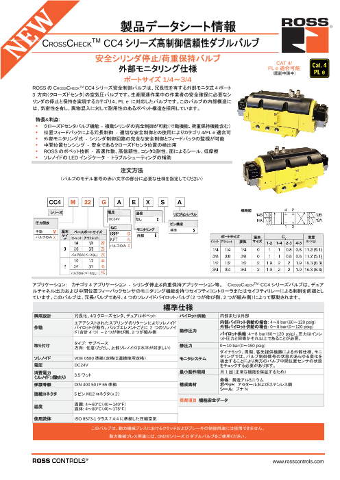
"安全性に関する注意事項"や"サービスおよびメンテナンス"などについて掲載!
当資料は、当社が取り扱う、安全排気(放出)制御用の
高制御信頼性ダブルバルブ『MCSEシリーズ』の取扱説明書です。
MCSEは安全リレーを組み込んだ内部モニタ式残圧排気弁です。
"本製品を使用するための前提条件"をはじめ"組立と設置"や
"お手入れとメンテナンス"、"仕様"などについて掲載。
製品を安全かつ適切に組立て、試運転するための重要な情報が
記載されておりますので、是非ご一読ください。
【掲載内容(一部)】
■このドキュメントについて
■安全性に関する注意事項
■製品識別
■本製品を使用するための前提条件
■パッケージ内容
※詳しくはPDF資料をご覧いただくか、お気軽にお問い合わせ下さい。
このカタログについて
| ドキュメント名 | 【取扱説明書】高制御信頼性ダブルバルブ『MCSEシリーズ』 内部モニタ式残圧排気弁 |
|---|---|
| ドキュメント種別 | 製品カタログ |
| ファイルサイズ | 18.5Mb |
| 登録カテゴリ | |
| 取り扱い企業 | ロス・アジア株式会社 (この企業の取り扱いカタログ一覧) |
この企業の関連カタログ


このカタログの内容
Page1
MCSE Series
RC-MCSE-OI
EN/DE/ES/FR/IT/PT-BR/RU/JA/ZN-CH
MCSE Series
MCSE Series – Safe Exhaust (Dump) Control Reliable Double Valves
Serie MCSE – Redundantes Sicherheitsventil mit internen Überwachung, Doppelventile mit zuverlässiger Steuerung
Serie MCSE – Escape de seguridad (vaciado) Válvulas dobles de control fiables
Série MCSE – Electrovane de Sécurité Modulaire Double Corps
Serie MCSE – Scarico di sicurezza (discarica) controllo affidabile valvole doppie
MCSE Series – Válvula de Segurança - Despressurização Assegurada
Серия MCSE – Безопасный выпуск (сброс) Надежные двойные регулирующие клапаны
MCSE シリーズ – 安全排気(放出)制御用 高制御信頼性ダブルバルブ
MCSE 安全排氣(排放)控制可靠的雙氣門
Operating Instructions
Betriebsanleitung
Instrucciones de servicio
Instructions d‘utilisation
Istruzioni operative
Instruções de Operação
Инструкция по эксплуатации
取扱説明書
使用说明书
Cat. 4 SIL 3 ISO HSM XXXXX
PL e Functional Safety Sicherheit geprüft 13849-1:2015tested safety
√
pending
Declaration of CE Conformity and Certifications available for download at www.rosscontrols.com.
Die CE-Konformitätserklärung und CE-Zertifizierungen können unter www.rosscontrols.com heruntergeladen werden.
Declaración de Conformidad CE y Certificaciones disponibles para descargar en www.rosscontrols.com.
Déclaration de conformité CE et certifications disponibles au téléchargement sur le site www.rosscontrols.com.
Dichiarazione di conformità CE e certificazioni disponibili per il download all’indirizzo www.rosscontrols.com
Declaração de Conformidade CE e Certificações disponíveis em www.rosscontrols.com
Декларация и сертификаты соответствия нормам ЕС доступны для скачивания на сайте www.rosscontrols.com.
CE 適合宣言書および認証は www.rosscontrols.com でダウンロードできます。
CE 符合性声明和认证可在 www.rosscontrols.com 下载
www.rosscontrols.com
Page2
English
ENGLISH MSCE Series Operating Instructions
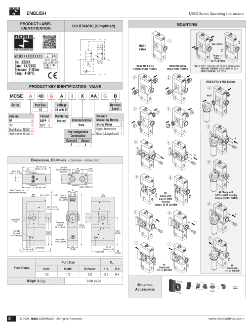
PRODUCT LABEL
SCHEMATIC (Simplified) MOUNTING
IDENTIFICATION
1
MCSE *REF. NOTES
Valve
Torque (τ)
(Max.):
54 FT-LB/73NM
ROSS MD Series ROSS MD Series *NOTE: PORT THREAD ARE AS PER STANDARDS:
FEMALE PORT FITTING MALE PORT FITTING FOR NPT THREAD: ANSI/ASME B1.20.1
FOR G THREAD: ISO 228-1
2 2
ROSS FRL’s MD Series
PRODUCT KEY IDENTIFICATION - VALVE 3
MCSE A 40 G A I X AA G B MCSE
Series Port Size Voltage Revision
1/2 24 volts DC Level 3 3
Version Thread Monitoring Pressure
PP A BSPP G Internal Communication Measuring Device
PM B NPT N None Analog Gauge G 4
Start-Button NCNC C Digital Transducer T
PIN Configuration
Start-Button NCNO D Combination None (plugged port) X
Solenoid Sensor 4 4
A A
4 x
DiMensionAl DrAwings - Dimension – Inches (mm) 5
167.8 ± 2.5 (2x) G1
65 (6.60 ± 0.10) Sintered Bronze 58 28.5
23 ± 1.5 (2.26) Silencer (2.28) (1.12)
(0.91 ± 0.06)
5 5
137 (5.39) SECTION A-A
M12 Connector 53
(Male and Female) (2.09) 4X 4X Clamp with
18 ± 3 (0.71 ± 0.12) Status Clamp with 5/32 or 4MM Hex Key
Indicator Torque: 35 IN-LB/4NM
(5 LED’s) 5/32 or 4MM
Hex Key
Torque: 35 IN-LB/4NM 6
287.5 ± 2.5
(11,32 ± 0.10)
6 6
(2x) G1/2
Port Pressure 4 x
Gauge 305.5
G 1/4 Port (12.03)
(2x) M3 165.1 165.1
Ground (6.50) (6.50)
Connection
Adjustable 7
Flow Control 7 7
68 ± 2 EXHAUST 6.3 68 ± 2
(2.68 ± 0.8) (2.48) (2.68 ± 0.8)
112 (4.41) 25
(0.98)
Port Size CV 4X 4X
Flow Rates Inlet Outlet Exhaust 1-2 2-3 Clamp with Clamp with 1/4” or M6 BOLT 1/4” or M6 BOLT
1/2 1/2 1/2 3.9 9.4
Weight lb (kg) 9.26 (4.2)
Mounting
Accessories
2 © 2 021, ROSS CONTROLS®. All Rights Reserved. www.rosscontrols.com
2
3
1
Page3
MCSE Series Operating Instructions ENGLISH
4
24 V DC
0 V GND 24 V
0
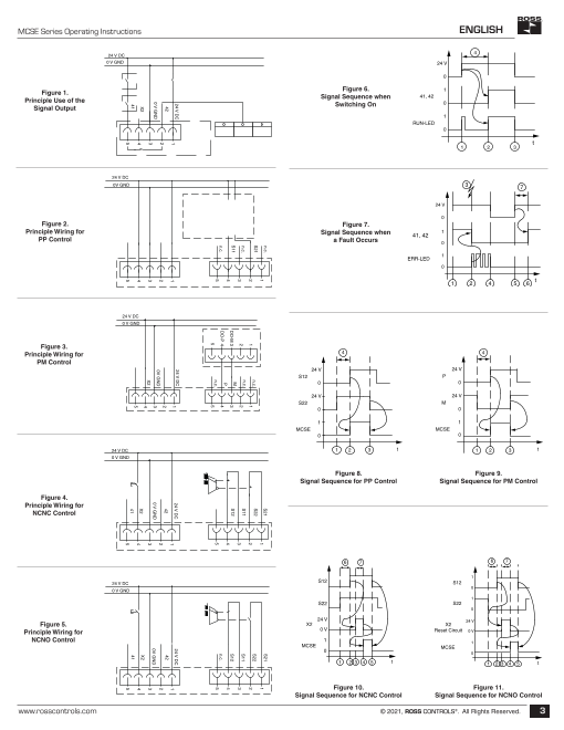
Figure 1. Figure 6. 1
Principle Use of the Signal Sequence when
41, 42
0
Signal Output Switching On
1
RUN-LED
0
t
1 2 3
24 V DC
0V GND 3 7
24 V
0
Figure 2. Figure 7.
Principle Wiring for Signal Sequence when 141, 42
PP Control a Fault Occurs 0
1
ERR-LED
0
1 2 4 5 6 t
24 V DC
0 V GND
Figure 3.
Principle Wiring for 4 4
PM Control
24 V 24 V
S12 P
0 0
24 V 24 V
S22 M
0 0
1 1
MCSE MCSE
0 0
24 V DC 1 2 3 t 1 2 3 t
0 V GND
Figure 8. Figure 9.
Signal Sequence for PP Control Signal Sequence for PM Control
Figure 4.
Principle Wiring for
NCNC Control
6 7 6 7
1
24 V DC S12 S12
0
0 V GND
1
S22 S22
0
24 V 24 V
Figure 5. X2 X2
Principle Wiring for 0 V Reset Circuit 0 V
NCNO Control 1 1
MCSE MCSE
0 0
1 2 3 4 5 t 1 2 3 4 5 t
Figure 10. Figure 11.
Signal Sequence for NCNC Control Signal Sequence for NCNO Control
www.rosscontrols.com © 2021, ROSS CONTROLS®. All Rights Reserved. 3
n.c. S21 S21
1 1 1
S21 n.c. S22 S22
2 1 1 2 2
n.c. n.c. S112 2 S113 3 3
S11 MDO-M 3 3 S12 S12
4 4 4
P
n.c. DO-P 4 4 n.c.
5 n.c. 5 5
5 5
24 V DC 24 V DC 1 24 V DC 24 V DC1 1 1 1
42 2 42 42
2 2 2 2
0V GND
0 V GND 3 0 V GND 0V GND
3 3 X2 3 3
4
X2
4 4 X2
X2
4 4
5
41 41 41
5 5 5 5
Page4
ENGLISH MSCE Series Operating Instructions
• Type or source of hazard: States the type of danger or the source of the hazard.
ROSS EUROPA GmbH • Robert-Bosch-Strasse 2 • D-63225 Langen • Consequences: Describes possible consequences of ignoring the warning.
Telefon: (06103) 7597- 0 • Fax: (06103) 74694 • e-mail: info@rosseuropa.com • www.rosseuropa.com Sitz: Langen • AG: Langen, B412 •
Geschäftsführer: Ralf W. Dinkel • Measures to avert danger: Indicates how to avoid the danger. It is essential that
the measures to avert danger are complied with.
EU declaration of conformity
(Original Version) Indicates an imminent and serious danger that will result in severe or
Product: ROSS® double valve MCSE DANGER even fatal injury if you fail to avoid it.
This declaration of conformity is issued under the sole responsibility of the manufacturer Indicates a possible danger that could result in severe or even fatal
are in full accordance with the following Directive: WARNING injury if you fail to avoid it.
Machinery Directive 2006/42/EC
EMC Directive 2014/30/EC Indicates a danger that may result in minor to moderate injuries if you
Applied harmonized standards: CAUTION fail to avoid it.
EN ISO 13849-1: 2015: Safety of Machinery
- Safety related parts of a control system -Part 1 ATTENTION Indicates potential property damage that may be incurred by the
EN ISO 13849-2: 2012: Safety of Machinery product or its surroundings if you fail to avoid it.
- Safety related parts of a control system -Part 2
EN ISO 60204-1: 2014-10: Safety of Machinery
- Electrical equipment of machines -Part 1 2. Notes on Safety
DIN EN 61508-1-7: 2010/2011: Functional Safety of electrical/ electronic/ programmable electronic safety-related The product has been manufactured according to the accepted rules of current
systems Part 1-7 (as applicable) technology.
DIN EN 62061: 2016-05: Safety of machinery – Functional safety of safety-related electrical,
electronic and programmable electronic control systems (as applicable) There is risk of injury or damage if the following safety instructions and warnings given
EN 61000-6-2:2005: Electromagnetic compatibility -: Generic standards - Immunity standard for in this instruction manual are not observed.
industrial environments (IEC 77/488/CDV:2015)
EN 61000-6-4:2007+A1:2011: Electromagnetic compatibility -: Generic standards - Emission standard for 2.1. Intended Use
industrial environments
EN ISO 4414: 2010-11: Pneumatic Fluid Power The MCSE Series double valves are safety components designed and manufactured
General Rules and Safety Requirements for Pneumatic in accordance with Machinery Directive 2006/42/EC. Its intended use is to control
Systems and their Components ventilation and exhaust in compressed air systems or similar applications, as well as
Applied non-harmonized standards: to avoid unexpected switch-on and release of energy in pneumatic tubing systems and
EN 61326-3-1: 2008: Electrical equipment for measurement, control and laboratory use end devices in the industry.
– EMC requirements – Part 3-1
The MCSE Series double valves are designed for safe, redundant operation and have
Tested in accordance to: GS-IFA-M07:2017-04 (as applicable) internal monitoring. The valves consist of redundant 3/2 valves and have the overall
Authorized person for the compilation of technical documentation: function of an externally piloted valve with spring return.
Andreas Jourdan f See section 12 “Technical Data” for the standards and test values complied with
ROSS EUROPA GmbH
Robert-Bosch-Strasse 2 and adhered to by the product. See the declaration of conformity for product-
63225 Langen / Germany relevant directives.
Intended use includes having read and understood this documentation, especially the
chapter 2 “Notes on safety”
Soft Start
The MCSE Series double valves have a soft start function (soft start). The function of
the soft start module is that the output pressure increases slower than normal during
pressurization, until it reaches approx. 50% of the inlet pressure. The valve then opens
fully at this point and fills the system with the full flow rate. This feature can be used to
reduce the surge of a sudden, quick pressure application of cylinders. This function is
Langen, 2019-06-16 Signed for and on behalf of particularly useful when inline flow controllers are placed in the cylinder control lines.
By fully opening the soft start, the soft start function could be disabled if not needed.
Dietrich Warmbier 2.1.1. Safety Function According to ISO 13849
Global Safety Product Manager
The MCSE Series safety valve is a redundant system according to the requirements
of ISO 13849-1 and -2, in which the pneumatic safety functions “safe exhaust” and
1. About this Documentation “prevention of unexpected start-ups” are ensured, including in case of a safety valve fault (e.g., due to wear).
These instructions contain important information for the safe and appropriate assembly The safety function of the 3/2 valve from the MCSE Series is that the machine/system
and commissioning of the product. is only supplied with pneumatic energy (compressed air) when the redundant electrical
f Read these instructions all the way through, particularly section 2. “Notes on
Safety”, before working with the product. control and therefore both valve elements are actuated simultaneously. The supply
with compressed air is switched off and the system is exhausted if the redundant
Additional documentation: electrical control is not available.
• SISTEMA libraries
• DGUV (formerly BG) certificate: German professional association The MCSE safety valve is designed in such a way so that the safe state (filling switch-
off and exhausting the operating line) is always ensured, even in case of a fault within
• Technical documents the valve (e.g., due to wear, contamination or similar situations). The control outputs of
For more information see last page for contact information, or visit www.rosscontrols. the electrical safety system must be designed and constructed in such a way that they
com. fulfill the requirements of the category and the performance level (PL) of the safety
f In addition, observe all applicable local and national regulations on accident system, which result from the machine’s risk assessment. With correct integration in
prevention and on environmental protection. the control system in accordance with ISO 13849-1 and -2, these products can be
1.1. Warning Notices in these Operating Instructions used in up to Category 3 and 4 and a performance level up to e can be achieved.
In these operating instructions, warning notices precede sections with handling The product has been engineered and manufactured according to the fundamental
requirements which incur risks of personal injury or material damage. and proven safety principles of ISO 13849-2.
Warnings are structured as follows: 2.1.2. Common Cause Failure – CCF
The product has been engineered and manufactured according to the fundamental
SIGNAL WORD and proven safety principles of ISO 13849-1 and -2 (e.g., measures for the software,
Type or source of hazard! diagnosis, against further CCF, against systematic failures etc.) and then evaluating
Consequences whether the necessary performance level has been achieved.
f Measures to avert danger Common Cause Failures (CCF) are failures of different components, resulting from
a single event. CCF are not to be confused with cascading faults or common mode
• Warning triangle: Indicates a risk of fatal or severe injuries. faults. Common cause failures can cause loss of the safety function, especially in dual
• Signal word: Indicates the severity of the danger. channel circuits where both channels could fail simultaneously due to a single event.
4 © 2 021, ROSS CONTROLS®. All Rights Reserved. www.rosscontrols.com
Page5
MCSE Series Operating Instructions ENGLISH
• Maintain compressed air quality, i.e., filtration, pressure regulation, lubrication. 5. Package Contents
• Avoid compressor oils that can cause valve seals to swell, soften, or otherwise
deteriorate. Items included:
• Conduct leakage tests of the load holding system, including the connecting lines, • MCSE Series double valve
fittings, and actuator seals, on commissioning and periodically during use. • Operating instructions
• Operate within prescribed temperature limits.
• Install the valve such that the normal stroke travel of the valve elements are 6. Service and Maintenance
perpendicular to the main direction of machine vibration and/or mechanical shock. f The MCSE valve is not repairable. Do not attempt to adjust or repair the valve.
• Avoid external magnetic fields. In case of technical problems or a required service, please contact your local
• Do not plug the valve exhaust port. ROSS representative. If used properly, the MCSE Series double valves will not
• Use only high-flow, non-clogging silencers, with similar or higher specifications as
® require maintenance. Unless otherwise required, ROSS
® recommends performing
ROSS silencers. a functional test at least once a month (see 8.1 Test Procedure).
2.1.3. Diagnostic Coverage
7. Assembly and Installation
A diagnostic coverage of 99% is achievable through appropriate integration of the
MCSE Series valve into the safety control system.
CAUTIONS
2.1.4. Improper Use Risk of injury due to installation while pressurized or with live parts!
Installation while pressurized or with electrical power switched on can result in
WARNING injuries due to sudden pressure build-up or electric shock.
Risk of Injury! f De-energize and de-pressurize the relevant system parts before installing the valves.
Misuse may result in injury or damage. f Secure the system to prevent it being switched back on again.
f The product must be used exclusively as intended.
The following applications are prohibited: ATTENTION
• Use outdoors Destruction of components!
• Use in non-industrial applications/residential areas
• Use outside of the product limits defined in the technical data Chemical substances can damage the surface, the markings and the seals of the device.
• Unauthorized modifications f Install the valve such that it is protected against the effects of chemicals.
• Use as a press safety valve to control a clutch or brake Damage to the device through storage at incorrect temperatures!
• Operation with a low demand rate (low demand mode) according to IEC 61508 The storage temperature represents the permissible ambient temperature and de-
• Bypassing the safety function or diagnostics pends on the type of valve in question.
• Use in reverse operation (reversal of supply and exhaust air, reversal of output f Observe the temperature information in chapter 12 “Technical Specifications.“
and supply)
ROSS CONTROLS is not liable for any damages resulting from improper use. The 7.1. Mechanical Installation
user alone bears the risks of improper use of the product. Prepare for assembly as follows:
2.2. Responsibilities of the System Owner 1. Stop system operation and protect it against being switched on.
• Observe the information on assembly and operating conditions listed in the 2. Return all suspended loads to a statically secure position or remove them from
operating instructions or the data sheet. the system.
• Comply with the further requirements of ISO 13849 (e.g., CCF, DC, PLr, software) 3. If required, exhaust stored compressed air from system parts in the immediate work area.
if you intend to use the product in higher categories (2, 3, or 4). 4. Make sure the relevant section of the system is not under pressure or voltage and
• Make sure that the maximum number of switching cycles (B10D) within the service protect it from being switched on.
life Tm is not exceeded. If the expected number of switching cycles for a component 5. Secure self-turning or other movable system parts before starting assembly.
exceeds the B10D value during its period of use, suitable replacement intervals have 6. Let the MCSE safety valve acclimatize itself for several hours before installation,
to be specified. otherwise water may condense in the housing.
• Switch the valve at least once a month to ensure its proper operation.
• Make sure that the fundamental and proven safety principles in accordance with Mount the Valve
ISO 13849 for implementation and operation of the component are complied with. To mount a single valve – See page 2.
• Make sure that the permissible positive and negative test pulses for feedback- To mount the valve as part of a maintenance unit – See page 2.
free operation of the pneumatic devices are observed (see chapter 12 “Technical The valve must be mounted on both sides with one mounting element each on the
Specifications“). mounting surface.
2.3. Safety Instructions 7.2. Pneumatic Installation
• When implementing surge suppression measures, be sure to check whether or
not this extends the valve shut off response time which could extend the machine Mount the pressure sensor or pressure gauge (optional)
stopping time. A pressure gauge or electronic pressure sensor can be connected to the thread
• In case of high levels of machine vibration, use appropriate vibration-reducing connection(see page 3) once the blanking plug has been removed.
elements when installing the valve. Observe the mounting instructions enclosed with the components.
• Supply the proper voltage as overvoltage situations can result in solenoid burnout.
• Make sure that the silencer’s flow capacity is not restricted as this could affect 7.3. Pneumatic and Electrical Connections
system performance. Pneumatic Connections
• If required, replace the silencer exclusively with a corresponding ROSS model. Requirement: The supply pressure must always be between 29 psig (2 bar) and up to
145 psig (10 bar).
3. Product Identification Note: The correct function of the MSCE safety valve is not guaranteed if the supply
pressure is lower than 29 psig (2 bar) and up to 145 psig (10 bar).
Product label identification & product key identification example, see page 2.
1. Connect the pressure line for the supply pressure to connection 1 (1, IN).
See back page for ROSS addresses. 2. Connect the operating line to connection 2 (2, OUT).
4. Prerequisites for Use of the Product Electrical Connections
f Make these operating instructions available to the engineer and assembly 1. Connect the supply voltage to plug XPS, the signal output, and, if applicable, start
technician of the machine/system in which the product will be used. signal X2.
f Keep these operating instructions for the entire product life cycle. The assignment of the XPS plug is the same for all versions.
The contacts on the XPS plug, M12 male have the following pin assignment:
4.1. Qualified Personnel
Assembly, installation, commissioning, maintenance, and decommissioning should
only be carried out by qualified personnel that have the required knowledge of and
experience in dealing with electrical and pneumatic control technology.
www.rosscontrols.com © 2021, ROSS CONTROLS®. All Rights Reserved. 5
Page6
ENGLISH MSCE Series Operating Instructions
XPS Pin Function 7.3.5. Principle Wiring for NCNC or NCNO Control
24 V DC
1 1 24 V DC supply voltage for the device When using the NCNC or NCNO control, the safety switches are supplied by the clock
42
2 2 Signal contact 42, potential-free signal (S21, S11). Safety input 1 (S12) is connected with S11 via the switch. Safety
0V GND input 2 (S22) is connected with S21 via the switch. Cross-circuits on the safety inputs
3 3 0 V
X2 are monitored by the MCSE safety valve in this control. Start (pressurization) takes
4 4 Input for start X2 place using the start input X2 in this control.
41 5 5 Signal contact 41, potential-free For principle wiring for NCNC control, see Figure 4 on page 3.
For principle wiring for NCNO control, see Figure 5 on page 3.
2. Connect the safety signals to control the device to plug X2D. Observe the different
assignment of plugs for different devices. The type of device can be taken from the 7.3.6. Principle Wiring for PM Control
name plate. Input M of the MCSE safety valve must be connected with the safe negative output
D0-M (e.g., safe output assembly) of a PLC. Input P of the MCSE safety valve must
7.3.1. Connecting the Supply Voltage be connected with the safe positive output D0-P (e.g., safe output assembly) of a
PLC. The “automatic start” function is used in this operating mode, therefore X2
WARNING must be connected with 24 V DC. The contacts have the following assignment for
PM control:
Risk of injury due to Electric shock due to incorrect power pack!
f Use a 24 V DC SELV or PELV circuit in accordance with DIN EN 60204-1 to connect X2D Pin Function
the power supply for the valve. nc 1 1 nc, not connected (not connect)
f The PELV power source must be a safety isolation transformer in accordance with nc 2 2 nc, not connected (not connect)
IEC 61558-1 or IEC 61558-2-6, or a power source offering the same degree of M 3 3 M-input (safety input 2)
safety as a safety isolation transformer. P 4
f Make sure that the power source for the SELV power pack adheres to DIN EN 60950. 4 P-input (safety input 1)nc 5
We recommend using a type Z (max. 2 A) circuit breaker or a micro-fuse (max. 1 A, 5 nc, not connected (not connect)
inactive) to protect the operating voltage.
For principle wiring for PM control, see Figure 3 on page 3.
7.3.2. Connect the Signal Contact 7.3.7. Connect Ground (FE, function potential compensation)
The device has a potential-free signal contact (41, 42). A loop covering all safety A ground connection is available on the device. To discharge EMC interferences,
modules can be achieved with this signal contact, for example. The maximum voltage connect the FE connection to the MCSE safety valve via a low-impedance line to
for the signal output is 24 V DC, and the maximum current is 0.2 A. functional earth. Using the valve without FE connection is not allowed.
The line cross-section must be selected according to the application and implemented
WARNING according to DIN EN 60204-1/IEC 60204-1.
Risk of injury due to valve malfunction!
A valve malfunction (e.g., failure to open the contact) may occur if you use signal outputs 8. Commissioning and Operation
in safety circuits.
f Never use signal outputs in safety circuits. CAUTIONS
Figure 1 on page 3 shows the principle use of the signal output. Danger of injury while working on the system!
Working while the system is running can cause major injuries from moving machinery.
7.3.3. Connect Start Input X2 f Maintain a sufficient safety distance to moving machine components.
f Do not work on the system while it is running.
WARNING Before commissioning, the installation must be carefully inspected by a qualified,
Risk of injury! trained professional.
The use of the “automatic start” function is only permissible in terms of IEC/EN 60204-1 in Make sure that the technical specifications match the operating criteria of the machine
conjunction with other appropriate measures for machine start-up! and/or the pneumatic system.
f Make sure that the MCSE safety valve cannot be activated when using the “automatic Make sure that all plugs are correctly connected. Always set the compressed air
start” function. For example, use an additional safety module with start button, which supply to a level that ensures that the minimum operating pressure is adhered to (see
prevents immediate switch on after release of an emergency OFF button or after applying section 12 Technical Specifications).
the operating voltage.
8.1. Take the MCSE Safety Valve into Operation
Start input X2 is not active during control with PP or PM. The MCSE safety valve Proceed as follows in order to take the MCSE safety valve into operation:
performs an automatic start. Start input X2 must be connected with 24 V DC. 1. Switch on the pneumatic supply.
Start input X2 is active during control with NCNC or NCNO. Start input X2 can be 2. Switch on the 24 V DC supply voltage.
connected with a button, for example. Activation of the MCSE safety valve starts when
the button is released. 8.1.1. “Pressurization” Function
Actuation of the button is monitored. The button may have a maximum actuation time If the MCSE safety valve should pressurize the machines, you must switch both safety
between 0.03 s and 3 s. Activation does not take place if the time is exceeded. inputs 1 and 2 with the right signal sequence. If the signal sequence is not correct, the
The contacts on the X2D plug, M12 female safety inputs have the following assignment: MCSE safety valve goes into the safe state. Exhausting of the operating line is the safe state.
8.1.2. “Exhaust” Function
X2D Pin Function
If the MCSE safety valve should exhaust the machines, you must switch both safety
S21 1 1 S21 clock signal for S22 inputs 1 and 2 with the right signal sequence. The MCSE safety valve goes into the
S22 2 2 S22 safety input 2 safe state if the MCSE safety valve is isolated from the supply voltage or if a fault
S11 3 3 S11 clock signal for S12 occurs during operation.
S12 4 Exhausting of the operating line is the safe state. 4 S12 safety input 1
nc Exhausting of the valve may not be restricted.5 5 nc, not connected (not connect)
8.1.3. Signal Sequence when Switching On
7.3.4. Principle Wiring for PP Control The following signal sequence results when switching on the MCSE safety valve (see
Figure 6 on page 3).
When using the PP control, safety inputs 1 and 2 must each be connected with a
safe output signal. The “automatic start” function is used in this operating mode. X2 is The MCSE safety valve is not supplied with 24 V DC before time 1. Signal output (41,
therefore connected with 24 V DC. 42) is open (41, 42=0) and the RUN-LED is off (0). The MCSE safety valve exhausts
For principle wiring for PP control, see Figure 2 on page 3. the operating line.
6 © 2 021, ROSS CONTROLS®. All Rights Reserved. www.rosscontrols.com
Page7
MCSE Series Operating Instructions ENGLISH
The MCSE safety valve is supplied with 24 V DC at time 1. The RUN LED and all other the pressurized state (MCSE=1) at time 4. OUT LED illuminates and indicates the
LEDs flash briefly when switched on. The device performs a self-test. This self-test activated state. The time for monitoring signal X2 is between a minimum of 0.03 s and
takes a maximum of 1.5 s. After the self-test (4) has been successfully carried out, maximum 3 s. If X2 is not actuated within this monitoring time, the MCSE safety valve
the MCSE safety valve is in the ready state (2). The RUN-LED (1) is illuminated in the remains in the exhausted state (MCSE=0).
ready state and the signal output is closed (41, 42=1). The MCSE safety valve is ready If the connection between S11 and S12 is opened via the corresponding switch after
for control via both safety inputs. time 4 or the connection between S21 and S22 is closed by the corresponding switch,
If the device is disconnected from the supply voltage at time 4, the MCSE safety valve goes into the non-activated state (AS3-SOV=0) and exhausts
• The MCSE safety valve exhausts, the operating line at time 5.
• the RUN LED is not illuminated and OUT LED is off. Both signal inputs 1 and 2 must be open/closed to re-pressurize. LED
• the signal output is open (41, 42=0). IN 1 and IN 2 are off in this state and Start-Button X2 need to be pressed again.
8.1.4. Signal Sequence for PP Control 8.1.7. Signal Sequence for PM Control
The following signal sequence results during PP control of the MCSE safety valve (see The following signal sequence results during PM control of the MCSE safety valve
Figure 8 on page 3). (see Figure 9 on page 3).
The MCSE safety valve is in the ready state before time 1, but is not activated. In this The MCSE safety valve is in the ready state but is not activated before time 1. In this
state (MCSE=0) the MCSE safety valve exhausts the operating line. state (MCSE=0) the MCSE safety valve exhausts the operating line.
Signal input S22 is actuated with 24 V at time 1. If signal input S12 is also actuated with Signal input M is actuated with 0 V at time 1. If signal input P is also actuated with 24 V
24 V within synchronization time (4), the MCSE safety valve goes into the pressurized within synchronization time (4), the MCSE safety valve goes into the pressurized state
state (MCSE=1) at time 2. OUT LED illuminates and indicates the activated state. (MCSE=1) at time 2. OUT LED illuminates and indicates the activated state.
The synchronization time for monitoring (4) is 0.5 s. The state of signal inputs 1 and 2 The synchronization time for monitoring (4) is 0.5 s. The state of signal inputs P and M
is displayed by the IN 1 LED and IN 2 LED. is displayed by the IN 1 LED and IN 2 LED.
If the interval between signal inputs 1 and 2 is longer than the synchronization time If the interval between signal inputs P and M is longer than the synchronization time
for monitoring, the MCSE safety valve remains in the non-activated state. In this state for monitoring, the MCSE safety valve remains in the non-activated state. In this state
(MCSE=0) the MCSE safety valve exhausts the operating line and OUT LED is not (MCSE=0) the MCSE safety valve exhausts the operating line and OUT LED is not
illuminated. The IN 1 LED and IN 2 LED flash fast and indicate that signal inputs 1 illuminated. The IN 1 LED and IN 2 LED flash fast and indicate that signal inputs 1 and
and 2 have not been actuated synchronously. If signal input 1 and/or signal input 2 2 have not been actuated synchronously.
is actuated with 0 at time 3, the MCSE safety valve goes into the non-activated state If signal input P is not actuated with 24 V or if signal input M is not actuated with 0
(MSCE=0) and exhausts the operating line. OUT LED is off. Signal inputs 1 and 2 at time 3, the MCSE safety valve goes into the non-activated state (MCSE=0) and
must be de-actuated before re-pressurize. The IN 1 and IN 2 LEDs are off in this state. exhausts the operating line. OUT LED is off.
The signal input must be at 0 V and signal input M not at 0 V to re-pressurize. The IN
8.1.5. Signal Sequence for NCNC Control 1 and IN 2 LEDs are off in this state.
The following signal sequence results during NCNC control of the MCSE safety valve 8.1.8. Signal Sequence when a Fault Occurs
(see Figure 10 on page 3).
The MCSE safety valve goes into the safe state if a fault occurs during operation of the
The MCSE safety valve is in the ready state before time 1, but is not activated. In this MCSE safety valve. Exhausting of the operating line is the safe state.
state (MCSE=0) the MCSE safety valve exhausts the operating line. If an error occurs:
Signal input S22 is connected with clock output S21 at time 1 via the switch. If
• The MCSE safety valve exhausts the operating line,
signal input S12 is connected with clock output S11 via the second switch within • opens the signal output and
synchronization time (6), the MCSE safety valve goes into the “wait for start” state at • the red LED shows a flash code for the fault.
time 2. The MCSE safety valve remains in the non-activated state (MCSE=0) and the
exhausts the operating line. OUT LED indicates this state by flashing slow. The following signal sequence results when a fault occurs (see Figure 7 on page 3).
The synchronization time for monitoring the signal inputs is 0.5 s. The state of signal The device works fault-free at time 1. The signal output (41, 42=0) opens at time 2 if
inputs 1 and 2 is displayed by the IN 1 LED and IN 2 LED. a fault (3) occurs. The ERR LED shows a fault number via a flash consisting of long
If the interval between signal inputs 1 and 2 is longer than the synchronization time and short sequences.
for monitoring, the MCSE safety valve remains in the non-activated state. In this state You can analyze the error with the help of this error number. The device is switched off
(MCSE=0) the MCSE safety valve exhausts the operating line and OUT LED is not at time 4 and the fault is rectified. If the device is switched on at time 5 and the fault
illuminated. The IN 1 LED and IN 2 LED flash fast and indicate that signal inputs 1 and has been rectified, the device is ready to operate again at time 6 after the self-test (7,
2 have not been actuated synchronously. approx. 1.0s).
If start signal X2 is changed from 0 V to 24 V (positive flank) at time 3 and is The following table shows an overview of flash codes with the corresponding cause
changed back from 24 V to 0 V (negative flank) at time 4, the MCSE safety goes into of fault.
the pressurized state (MCSE=1) at time 4. OUT LED illuminates and indicates the
activated state. The time for monitoring signal X2 is between a minimum of 0.03 s and Flashes Error Cause
maximum 3 s. If X2 is not actuated within this monitoring time, the MCSE safety valve LED Long Short
remains in the exhausted state (MCSE=0).
If the connection between S11 and S12 or between S21 and S22 is interrupted via the 1 1 Supply voltage too low
corresponding switch after time 4, the MCSE safety valve goes into the non-activated 1 2 Supply voltage too high
state (MCSE=0) and exhausts the operating line at time 5. OUT LED is off. Both signal 2 4 Cross-circuit between inputs S12 and S22
inputs 1 and 2 must be open/interrupted to re-pressurize. The IN 1 and IN 2 LEDs are
off in this state, and Start-Button X2 need to be pressed again. 4 3 Supply voltage is detected as an AC voltage
3 8 Time monitoring during pressurization
8.1.6. Signal Sequence for NCNO Control
ERR 3 9 Time monitoring during exhaust
The following signal sequence results during NCNO control of the MCSE safety valve 4 1 Time monitoring during exhaust
(see Figure 11 on page 3).
The MCSE safety valve is in the ready state before time 1, but is not activated. In this 4 2 Time monitoring during exhaust
state (MCSE=0) the MCSE safety valve exhausts the operating line. 3 4 Undefined level on input X2
The switch opens the connection between signal input S22 and clock output S21 at 2 9 Undefined level on input S12
time 1. If signal input S12 is connected with clock output S11 via the second switch
within synchronization time (6), the MCSE safety valve goes into the “wait for start” 3 1 Undefined level on input S22
state at time 2. The MCSE safety valve remains in the non-activated state (MCSE=0)
and the exhausts the operating line. OUT LED indicates this state by flashing slow. 8.2.1. LED Displays
The synchronization time for monitoring the signal inputs is 0.5 s. The state of signal The LEDs flash briefly if the MCSE safety valve is supplied with 24 V.
inputs 1 and 2 is displayed by the IN 1 LED and IN 2 LED.
If the interval between signal inputs 1 and 2 is longer than the synchronization time The normal non-activated operating state (exhaust) is:
for monitoring, the MCSE safety valve remains in the non-activated state. In this state • RUN: illuminated
(MCSE=0) the MCSE safety valve exhausts the operating line and OUT LED is not • IN 1, IN 2, OUT, ERR: off
illuminated. The IN 1 LED and IN 2 LED flash fast and indicate that signal inputs 1 and The normal activated operating state (pressurize) is:
2 have not been actuated synchronously. • RUN, IN 1, IN 2, OUT: illuminated
If start signal X2 is changed from 0 V to 24 V (positive flank) at time 3 and is
changed back from 24 V to 0 V (negative flank) at time 4, the MCSE safety goes into • ERR: off
www.rosscontrols.com © 2021, ROSS CONTROLS®. All Rights Reserved. 7
Page8
ENGLISH MSCE Series Operating Instructions
The following table shows an overview of LED displays with the corresponding function. • Immediately exchange the MCSE safety valve if the seals are defective.
• Check regularly whether all plug connectors are firmly fitted.
LED Color Display Type Function • Establish the maintenance intervals according to your ambient conditions and
enter them in the system-dependent maintenance plan.
RUN Green Permanently illuminated The MCSE safety valve is ready
• Observe the system-specific maintenance intervals.
IN 1 Green Off Safety input 1/P not actuated In case of any maintenance requirements, it is advisable to replace the entire MCSE
IN 1 Green Permanently illuminated Safety input 1/P actuated safety valve as this is the only way of ensuring a life cycle value for the entire valve.
IN 1 Green Flashes quickly Time for synchronization exceeded Note: The operator is responsible for determining the maintenance intervals.
IN 1 Green Flashes slowly Second input S22 has not opened 10. Disassembly and Exchange
IN 2 Green Off Safety input 2/M not actuated
IN 2 Green Permanently illuminated Safety input 2/M actuated WARNING
IN 2 Green Flashes quickly Time for synchronization exceeded
Risk of injury if disassembled under pressure or voltage!
IN 2 Green Flashes slowly Second input S12 has not opened Uncontrolled movement of the system components!
Out Green Off MCSE safety valve in the non-activated state, f Make sure that the system is not under pressure or voltage when you disassemble operating line is being exhausted the MCSE safety valve.
Out Green Permanently illuminated MCSE safety valve in the activated state
ATTENTION
Out Green Flashes slowly The MCSE safety valve is waiting for start signal X2 Contamination during disassembly!
ERR Red Off No error During disassembly, greases or lubricant may escape from the MCSE safety valve.
ERR Red Flashes slowly See “Signal sequence when a fault occurs“ f Make sure that the environment is not contaminated with greases or lubricant during
ERR Red Flashes quickly See “Signal sequence when a fault occurs“ disassembly.
Disassemble the MCSE
8.2.2. Soft Start
If the MCSE safety valve is activated, the operating line is pressurized. The time 1. Stipulate a signal on safety inputs 1/2 to deactivate the MCSE safety valve and to
required for the output pressure to reach approx. 50% of the input pressure can be exhaust the outlet line on outlet connection 2.
changed with the help of the “soft start function”. For this, you must turn the adjustment 2. Switch off the 24 V DC supply.
screw for the “soft start function” (see page 2). 3. Remove the connected plugs.
If you turn the adjustment screw in a clockwise direction, the time required for the 4. Switch-off the supply pressure and exhaust the supply line.
output pressure to reach approx. 50% of the input pressure is increased. Turn the 5. Remove the pneumatic lines.
adjustment screw in an anti-clockwise direction to reduce the time. By fully opening the 6. Remove the valve fastening screws depending on the mounting type
soft start, the soft start function could be disabled if not needed. This concludes the disassembly.
Note: The time interval is directly influenced by the volumes of the system that is Exchange the MCSE
currently being filled. The time to reach 50% of the input pressure is longer in systems
with larger volumes than in systems with smaller volumes. 1. Disassemble the MCSE safety valve as described above.
2. Assemble a new MCSE safety valve as described in chapter “Assembly“.
9. Care and Maintenance
11. Troubleshooting
ATTENTION
Damage to the product due to the use of solvents and aggressive cleaning agents! WARNING
The product can be damaged if washed with a solvent or aggressive cleaning agent. The Risk of injury by dismantling the valve!
chemical resistance of the valve material to such products is not guaranteed. Solvents Pre-tensioned springs may suddenly be released when dismantling the valve.
and aggressive detergents will destroy the surface, labeling and seals of the product. f Never dismantle the valve.
f Make sure that no solvents and aggressive cleaning agents come into contact with f Do not attempt to perform any unauthorized repairs.
the valve.
Damage to the product due to washing at high pressures and temperatures! • Check the connections, operating voltage, and working pressure of the relevant
The product will be damaged if you clean it with high pressure and/or at a high temperature. system part if malfunctions occur.
f Make sure that the product is not cleaned with high pressure and/or at a high Additional help for malfunctions can be found in the following table:
temperature.
Malfunction Possible cause Remedy
No special care is required for the MCSE safety valve. Note the following if you would
like to clean the valve: Pressure/flow level is Operating pressure is too Increase the operating pressure
• Check that all seals and plugs for the plug connections are firmly seated so that no not reached or drops off low Check tubing diameter
humidity can penetrate the MCSE safety valve during cleaning. slowly Leak on tubing Check tubing and tubing connections
• Only clean the MCSE safety valve using a slightly damp cloth. Only use water to do No output pressure on Troubleshooting using the LED
this and, if necessary, a mild detergent. output 2 and LED display
differs from the normal Incorrect control display (Normal state: RUN, IN 1, IN 2
display (see below) and OUT illuminate, ERR is off)
WARNING Supply a voltage to the device
Risk of injury while working on a running system! RUN LED is OFF
Device is not supplied with
a voltage according to the instructions
Working while the system is running can cause major injuries from moving machinery.
LED IN 1, IN 2 OFF The corresponding safety Check the wiring and control of safety f Bring the system mode into a state in which working movements are no longer input does not have a signal inputs
possible. Wait until all moving machine parts come to a standstill, and protect the Control of signals IN 1 and
system against being switched on. The IN 1, IN 2 LEDs IN 2 outside of the Check signal sequence on IN 1 and
flash quickly IN 2synchronization time
In normal operation, the MCSE safety valve is maintenance-free. However to ensure
proper function, the MCSE safety valve must be actuated at least once per month. Check the wiring and control of theOUT LED flashes slowly No start signal on X2
start signal
The MCSE safety valve seals may age faster in aggressive ambient conditions. A Establish the fault number using
damaged seal can be recognized by parts of the seal visibly protruding from the An error has occurred in the flash code and carry out
housing gaps. Defective seals will lead to pneumatic leaks. ERR LED flashes the device troubleshooting in accordance with
• Regularly check that the seals are in perfect order. “Signal sequence when a fault occurs“.
8 © 2 021, ROSS CONTROLS®. All Rights Reserved. www.rosscontrols.com
Page9
MCSE Series Operating Instructions ENGLISH
Additional help for malfunctions can be found in the following table: Vibration Resistance (DIN EN 60068-2-6): 0.35 mm ± 0.05 mm displacement at 10
If you are unable to troubleshoot the MCSE safety valve malfunction yourself: Hz–55 Hz.
Shock Resistance (DIN EN 60068-2-27): 30 g with 18 ms duration.
• Disassemble the MCSE safety valve as described in chapter 10 “Disassembly and Shock Wave Form: Sinus half-wave.
Exchange” and send it to ROSS CONTROLS. You can find the address on the back Safety Classification: Max. category 4, PL e, SIL 3.
of the operating instructions. Mean Time to Dangerous Failure: See B10D from the ROSS SISTEMA library.
ERR Common Cause Failure – CCF: > 65.
Error Number Diagnostic Coverage (DC): High, 99%.
Flashes Explanation of Errors Remedy Monitoring: Dynamic, cyclic, internal.
Short Noise Level [dB (A)]: The sound pressure level is influenced by the individual Long systems to reduce noise emissions. Exhausting of the valve may not be restricted. We
1 1 Supply voltage too low Increase the power supply. Use a cable do not recommend using the product without silencers.with a larger diameter Minimum Operation Frequency Recommended: 1 x per month, to ensure proper
1 2 Supply voltage too high Reduce the power supply function.
2 4 Cross-circuit between inputs
Maximum Cycle Rate: 2 Hz.
S12 and S22 Check the wiring and correct if necessary Mounting Orientation: Any, preferably vertical.
Supply voltage is detected as an Select a supply voltage according to the Solenoids: Per VDE 0580. Rated for continuous duty. Electrical connection according 4 3 AC voltage technical data to EN 175301-803 Form C. Enclosure rating according to DIN 400 50 IP 65.
Flow Rates: See page 2.
3 8 Time monitoring during Check the compressed air supply. Change pressurization the soft start setting.
4 1 Time monitoring during exhaust Silencer blocked, replace silencer 13. Disposal
4 2 Time monitoring during exhaust Silencer blocked, replace silencer Dispose of the valve in accordance with the applicable statutory regulations in your
3 4 Undefined level on input X2 Check the signals on plug XPS and the
country.
wiring
2 9 Undefined level on input S12 Check the signals on plug X2Dand the wiring
3 1 Undefined level on input S22 Check the signals on plug X2D and the wiring
12. Technical Specifications
Design: Redundant 3/2 Normally Closed double valve internally monitored.
Actuation: Electromagnetically externally piloted with air-assisted spring return.
One magnet per valve element (2 in total) - both must be operated simultaneously.
Flow Media: Permissible medium Compressed air (neutral gases) acc. to ISO 8573-1
Max. particle size 5-μm. Oil content of compressed air 0…1 mg/m3.
The oil content of compressed air must remain constant during the life cycle.
Operating Pressure Range: 30 to 150 psig (2 to 10 bar).
Ambient/Media Temperature: 40° to 120°F (+4° to 50°C). For temperatures below
4°C, the compressed air must be dried according to ISO 8573-3, class 7.
Standard Voltage: 24 volts DC.
Supply Voltage: For CSA/UL compliance, in DC applications the valve must be
connected to a NEC Class 2 power supply.
Electrical Data
Power pack/main supply SELV power pack in accordance with
Supply voltage DIN EN 60950 for operation in a PELV circuit in accordance
with EN/IEC 60204-1
Inputs S12, S22, X2 24 V DC, 8 mA
Clock output S11, 21 20 V DC, 10 mA per output
Cable length 1500 m at 1.5 mm²2500 m at 2.5 mm²
Line resistance max. 40 Ω
Power consumption 280 mA
Protection class according IP65 (only when assembled and with all plugs
to IEC 60529/EN 60529 connected)
Electrical connections 1x plug and 1x socket, 5-pin, M12
Tightening delay < 150 ms
Drop-out delay In case of emergency stop: < 10 msIn case of power failure: < 10 ms
Override time in case of
voltage drop 5 ms
Time until ready for
operation after switch on < 1.5 s
Switching capacity of
signal outputs 41–42: 24 V DC, 0.2 A
SAFETY CLASSIFICATION:
Directives: 2006/42/EC (Machinery Directive) 2004/108/EC (EMC directive)
Standards: ISO 13849-1, IEC61508/IEC62061, DIN EN 61326-3-1.
Test Principle: GS-IFA-M07, April 2017.
Safety Functions: “Safe exhaust” and “protection against unexpected start-up”.
www.rosscontrols.com © 2021, ROSS CONTROLS®. All Rights Reserved. 9
Page10
Deutsch
DEUTSCH Betriebsanleitung Serie MCSE
IDENTIFIZIERUNG ÜBER SCHEMATISCHE DARSTELLUNG MONTAGE
DAS PRODUKTETIKETT (vereinfacht)
1
MCSE *REF. HINWEISE
Ventil
Anzugsdreh-
moment ( τ )
(Max.):
54 FT-LB/73NM
*HINWEIS: ANSCHLUSSGEWINDE ENTSPRECHEN
ROSS MD Serie ROSS MD Serie DEN NORMEN:
INNENGEWINDEANSCHLUS S AUSSENGEWINDEANSCHLUS S FÜR NPT GEWINDE: ANSI/ASME B1.20.1
FÜR G GEWINDE: ISO 228-1
2 2
ROSS FRL’s MD Serie
VENTIL-IDENTIFIZIERUNG MITTELS PRODUKTSCHLÜSSEL 3
MCSE
MCSE A 40 G A I X AA G B
Serie Anschlussgröße Spannung Änderungs-
3 3
1/2 24 Volt DC stand
Version Überwachung Druck-
PP A Intern Kommunikation Messvorrichtung
PM B Keine Manometer G 4
Gewinde
Start-Taste NCNC C Digitaler
BSPP G Kombination der TStart-Taste NCNO D Druckschalter
NPT N PIN-Konfiguration Keine (verschlossener
Magnet Sensor Anschluss) X 4 4
A A
4 x
MAsszeichnungen - AbMessungen - Zoll (mm)
5
167,8 ± 2,5 (2x) G1
65 (6,60 ± 0,10) Gesinterte Bronze 58 28,5
23 ± 1,5 (2,26) Schalldämpfer (2,28) (1,12)
(0,91 ± 0,06)
5 5
137 (5,39) SCHNITT A-A
M12 Anschluss 53
(Außen- und Innengewinde) (2,09)
18 ± 3 (0,71 ± 0,12) Zustands- 4X 4 x Festziehen mit
anzeige Festziehen mit 5/32 oder 4MM Inbusschlüssel(5 LEDs)
5/32 oder 4MM Anzugsdrehmoment: 35 IN-LB/4NM
Inbusschlüssel
287,5 ± 2,5 Anzugsdrehmoment: 35 IN-LB/4NM 6
(11,32 ± 0,10)
6 6
(2x) G1/2
Anschluss Manometer
305,5 4 x
G 1/4 Anschluss (12,03)
(2x) M3
Erdungs- 165,1
165,1
(6,50) (6,50)
anschluss
Einstellbare
Durchfluss- 7
regelung
6,3 768 ± 2 ENTLÜFTUNG 68 ± 2 7
(2,68 ± 0,8) (2,48) (2,68 ± 0,8)
112 (4,41) 25
(0,98)
Anschlussgröße CV
4X 4X
Durchflussmengen Einlass Auslass Entlüftung 1-2 2-3 Festziehen mit Festziehen mit
1/4“ oder M6 SCHRAUBE 1/4“ oder M6 SCHRAUBE
1/2 1/2 1/2 3,9 9,4
Gewicht lb (kg) 9,26 (4,2)
MontAgezubehör
10 © 2 021, ROSS CONTROLS®. All Rights Reserved. www.rosscontrols.com
2
3
1
Page11
Betriebsanleitung Serie MCSE DEUTSCH
4
24 V DC
0 V GND 24 V
0
1
41, 42
Abbildung 1. Abbildung 6. 0
Prinzip der Verwendung Signalfolge beim
des Signalausgangs 1Einschalten RUN-LED
0
t
1 2 3
24 V DC
0V GND 3 7
24 V
0
Abbildung 2. Abbildung 7. 141, 42
Prinzip der Verdrahtung Signalfolge bei Auftreten 0
für PP-Steuerung eines Fehlers
1
ERR-LED
0
1 2 4 5 6 t
24 V DC
0 V GND
4 4
Abbildung 3.
Prinzip der Verdrahtung 24 V 24 V
für PM-Steuerung S12 P
0 0
24 V 24 V
S22 M
0 0
1 1
MCSE MCSE
0 0
24 V DC 1 2 3 t 1 2 3 t
0 V GND
Abbildung 8. Abbildung 9.
Signalfolge für PP-Steuerung Signalfolge für PM-Steuerung
Abbildung 4.
Prinzip der Verdrahtung
für NCNC-Steuerung
6 7
6 7
1
24 V DC S12 S12 0
0 V GND
1
S22 S22
0
24 V 24 V
Abbildung 5. X2 X20 V 0 V
Prinzip der Verdrahtung Rücksetzschaltung
für NCNO-Steuerung 1 1
MCSE MCSE
0 0
1 2 3 4 5 t 1 2 3 4 5 t
Abbildung 10. Abbildung 11.
Signalfolge für NCNC-Steuerung Signalfolge für NCNO-Steuerung
www.rosscontrols.com © 2021, ROSS CONTROLS®. All Rights Reserved. 11
n.c. S21 S21
1 1 1
S21 n.c. S22 S22
2 1 1 2 2
n.c. n.c. S11 S11
3 2 2 3 3
S11 MDO-M 3 3 S12 S12
4 4 4
P
n.c. DO-P 4 4 n.c.
5 n.c. 5 5
5 5
24 V DC 24 V DC 1 24 V DC 24 V DC1 1 1 1
42 2 42 42
2 2 2 2
0V GND
0 V GND 3 0 V GND 0V GND
3 3 X2 3 3
4
X2
4 4 X2
X2
4 4
5
41 41 41
5 5 5 5
Page12
DEUTSCH Betriebsanleitung Serie MCSE
kann. Es ist unbedingt erforderlich, dass die Maßnahmen zur Gefahrenabwehr
RROOSSSS EEUURROOPPAA GGmmbbHH ●• RRoobbeerrtt--BBoosscchh-S-Strtarßaes s2e ● 2 D •-6 D3-262352 L2a5n gLeanngen
TTeelleeffoonn:: ((0066110033)) 77559977-- 00 •● F Faxa:x (:0 (60160130)3 7)4 7649649 •4 e●- mE-aMil:a iinl:f oin@for@ossroesusreouprao.cpoam.c o•m w w●w w.rwosws.erousrsoepau.rcoopma. Scoitmz: LSaitnzg:e Lna •n gAeGn: L●a nAgGen: ,L Ba4n1g2e •n , B412 ● ergriffen werden.
Geesscchhääffttssffüühhrreerr:: RRaallff W. .D Dininkekle I Zeigt eine drohende und ernste Gefahr an, die bei Nichtvermeidung
EEUU d-eKcolnarfoatrimonit äotfs ceorknlfäorrumngity GEFAHR zu schweren oder tödlichen Verletzungen führt.
(Über(sOertizguinagl dVeesr sOioring)inals)
Zeigt eine mögliche Gefahr an, die bei Nichtvermeidung zu schweren
Produkct: R ROOSSSS®® D dopupbelelv veanltvile M MCCSSEE WARNUNG oder tödlichen Verletzungen führen kann.
DThieis a dlleicnlaigrea tVioenra onft wconrtfuonrmg iftüyr i sd iies sAuuesds tuenllduenrg t hdeie soelre K roenspfoornmsiitbäitlsiteyr kolfä trhuen gm tarnäugfta dcetur rHeer rsteller.
Zeigt eine Gefahr an, die bei Nichtvermeidung zu leichten bis
eanrets ipnr ifcuhllt avcocllosrtdäanndcige dweinth f othlgee fnodlloewn iRngic hDtilrineicetniv:e :
Mascchhinineeryn rDicirhetlcintiive VORSICHTe 2006/42/EC 2006/42/EG mittelschweren Verletzungen führen kann.
REiMchCtl iDniiere ücbtievre d ie elektromagnetis2ch0e1 4V/e3r0tr/äEgCli chkeit 2014/30/EU
ACHTUNG Zeigt die Gefahr von möglichen Sachschäden am Produkt oder seiner
Anpgpeliweda nhdatrem hoanrimzeodn sistiaenrdtea rNdosr:m en: Umgebung an, wenn diese Gefahren nicht vermieden werden.
EN IISO 13849--1:: 2015:: Siacfheetyrh oefi tM vaocnh Minaesryc hinen
- Siacfheetyrh reiltastbeedz poagretsn eo fT eai lceo vnotrno lS styesutermun -gPeanr t– 1 T eil 1 2. Sicherheitshinweise
EN IISO 13849--2:: 2012:: Siacfheetyrh oefi tM vaocnh Minaesryc hinen
- Siacfheetyrh reiltastbeedz poagretsn eo fT eai lceo vnotrno lS styesutermun -gPeanr t– 2 T eil 2 Das Produkt wurde gemäß den anerkannten Regeln der aktuellen Technologie hergestellt.
EN IISO 60204--1:: 2014--10:: Siacfheetyrh oefi tM vaocnh Minaesryc hinen Werden die folgenden Sicherheitsanweisungen und Warnungen in dieser Betriebsan-
- Elekctrisccahl e qAuuipsmrüesntutn ogf emn avcohnin Mesa s-Pchairnte 1n – Teil 1 leitung nicht beachtet, besteht die Gefahr von Personen- oder Sachschäden.
DIIN EN 61508--1 --7:: 2010//2011: Funkctionale S Saifcehtye rohfe eitl escictrhicearhl/ eeitlesbcterzoongice/ nperro gerleakmtrmisacbhler /elleckttrroniics cshaefer/ty-related
psyrosgteramms mPiaerrtb 1a-r7e r( aesle akptrpolnicisacbhlee)r Systeme Teil 1 - 7 (soweit zutreffend) 2.1. Bestimmungsgemäße Verwendung
DIIN EN 62061:: 2016--05:: Siacfheetyrh oefi tm vaocnh Minaesryc h–i nFeunn c- tFiounnaklt isoanfaeltey Sofi cshaeferhtye-irt esliactheedr heeleitcstbrieczaol,g ener
ellekcttrriosncihce ar,n edl epkrotrgornaismcmhearb ulen de lepcrotrgornaimc mcoienrtrboal rseyr setelemktsr o(naiss cahpeprl icable) Bei den Doppelventilen der MCSE Serie handelt es sich um Sicherheitsbauteilen, die
EN 61000-6-2:2005: SEtleecuterorumnaggsnsyestitce mcoem (psaotwibeiliitt yz u-:t rGeffeennedri)c standards - Immunity standard for in Übereinstimmung mit der Maschinenrichtlinie 2006/42/EG entwickelt und hergestellt
EN 61000-6-2:2005: Einldeukstrtorimala egnnveirtiosncmhee nVtesr t(rIäEgCli c7h7k/4e8it 8–/:C FDaVc:h2g0r1u5n)d normen – Störfestigkeit für wurden. Diese Ventile sind für die Steuerung der Be- und Entlüftung in Druckluftsys-
EN 61000-6-4:2007+A1:2011: IEnldeucstrtorimebaegrneeictihce c (oImECpa 7ti7b/i4li8ty8 -/C: GDeVn:2e0ri1c5 s)tandards - Emission standard for
EN 61000-6-4:2007+A1:2011: E temen oder ähnlichen Anwendungen sowie für die Vermeidung von ungewolltem Ein- inldeukstrtorimala egnnveirtiosncmhee nVtesr träglichkeit –: Fachgrundnormen – Störaussendung für
Industriebereiche schalten und Abgeben von Energie in Pneumatikrohrleitungssystemen und Endgeräten
EN ISO 4414: 2010-11: Pneumatic Fluid Power
EN ISO 4414: 2010-11: FGleunideteraclh Rnuikles and Safety Requirements for Pneumatic in der Industrie bestimmt.
SA yllsgteemesi naen dR ethgeeirln C uonmdp soicnheenrthse itstechnische Anforderungen
an Pneumatikanlagen und deren Bauteile Die Doppelventile der MCSE-Serie sind für einen sicheren, redundanten Betrieb ausge-
Applied non-harmonized standards: legt und verfügen über eine interne Überwachung. Das Ventil besteht aus redundanten
Angewandte nicht harmonisierte Normen:
EN 61326-3-1: 2008: Electrical equipment for measurement, control and laboratory use 3/2-Ventilen und erfüllt die allgemeine Funktion eines extern gesteuerten Ventils mit Fe-
EN 61326-3-1: 2008: E– lEekMtrCis crehqeu Miremsse-n, tSst e–u Pear-r,t R3-e1g el- und Laborgeräte
- EMV-Anforderungen - Teil 3-1 derrückstellung.
Tested in accordance to: GS-IFA-M07:2017-04 (as applicable) f Standards und Testwerte, die das Produkt erfüllt und einhält, finden Sie in Ab-
Geprüft nach: GS-IFA-M07:2017-04 (soweit zutreffend)
Authorized person for the compilation of technical documentation: schnitt 12 „Technische Daten“. Produktrelevante Richtlinien finden Sie in der Kon-
BAenvdorellamsä Jcohutirgdtearn für die Zusammenstellung der technischen Unterlagen: formitätserklärung.
ARnOdSreSa Es UJoRuOrdPaAn GmbH
ROobSeSrt -EBUoRscOhP-SAt rGamssbeH 2 Zur bestimmungsgemäßen Verwendung gehört das Lesen und Verstehen dieser Doku-
R63o2b2e5rt -LBaonsgcehn- S/ tGraeßrem 2a ny mentation, insbesondere des Kapitels 2 „Sicherheitshinweise“.
63225 Langen / Deutschland
Soft-Start
Die Doppelventile der MCSE-Serie verfügen über eine Soft-Start Funktion (sanfter
Anlauf). Die Funktion des Soft-Start Moduls besteht darin, dass der Ausgangsdruck
während der Druckbeaufschlagung langsamer als normal ansteigt, bis er ca. 50 % des
Eingangsdrucks erreicht. Das Ventil öffnet an diesem Punkt dann vollständig und das
System wird mit der vollen Durchflussmenge gefüllt. Diese Funktion kann verwendet
werden, um Stöße durch eine plötzliche, schnelle Druckbeaufschlagung der Zylinder
zu reduzieren. Diese Funktion ist besonders nützlich, wenn die Steuerleitungen der
Langen, 1260.1096-.0260-196 UnterSziegincehdn efot rf üarn udn odn i mbe Nhamlf eonf von Zylinder mit Durchflussreglern ausgerüstet sind.
Wenn die Soft-Start Funktion nicht benötigt wird, kann sie durch vollständiges Öffnen
des Soft-Starts deaktiviert werden.
DDieitertircihch W Waramrmbibeire r
GGlolobbala Sl Safaefteyt yP Prorodduuctc tM Mananagagerer 2.1.1. Sicherheitsfunktion nach ISO 13849
1. Über diese Dokumentation Bei dem Sicherheitsventil der MCSE-Serie handelt es sich um ein redundantes System gemäß den Anforderungen der ISO 13849-1 und -2, bei dem die pneumatischen Sicher-
Diese Anleitung enthält wichtige Informationen für die sichere und sachgerechte Mon- heitsfunktionen „sichere Entlüftung“ und „Verhinderung von unvorhergesehenen Anläu-
tage und Inbetriebnahme des Produkts. fen“ auch im Falle eines Fehlers des Sicherheitsventils (z. B. durch Verschleiß) gewähr-
f Lesen Sie sich diese Anweisungen vollständig durch, vor allem Abschnitt 2 „Si- leistet sind.
cherheitshinweise”, bevor Sie mit der Arbeit mit dem Produkt beginnen. Die Sicherheitsfunktion des 3/2-Ventils der MCSE-Serie beruht darauf, dass die Ma-
Zusätzliche Dokumentation: schine/Anlage nur dann mit pneumatischer Energie (Druckluft) versorgt wird, wenn die
• SISTEMA-Bibliotheken redundante elektrische Steuerung und damit beide Ventilelemente gleichzeitig ange-
• DGUV (vormals BG)-Zertifikat: Deutscher Berufsverband steuert werden. Die Druckluftversorgung wird abgeschaltet und das System entlüftet,
• Technische Unterlagen wenn die redundante elektrische Steuerung ausgefallen ist.
Mehr Informationen zu den Ansprechpartner finden Sie auf der letzten Seite, oder Das MCSE Sicherheitsventil ist so konstruiert, dass der sichere Zustand (Abschal-
besuchen Sie uns unter www.rosscontrols.com. ten der Befüllung und Entlüften der Betriebsleitung) auch bei einer Störung innerhalb
des Ventils (z. B. durch Verschleiß, Verschmutzung oder ähnliche Zustände) immer
f Beachten Sie zusätzlich sämtliche anwendbaren nationalen Richtlinien zu Unfall- gewährleistet ist. Die Steuerausgänge des elektrischen Sicherheitssystems müssen
verhütung und Umweltschutz. so ausgelegt und ausgeführt sein, dass sie die Anforderungen der Kategorie und des
1.1. Warnhinweise in dieser Betriebsanleitung Performance Levels (PL) des Sicherheitssystems, die sich aus der Risikobeurteilung
In dieser Betriebsanleitung stehen die Warnhinweise am Beginn der Abschnitte, die An- der Maschine ergeben, erfüllen. Bei richtiger Integration in das Steuerungssystem
weisungen enthalten, die mit einem Risiko von Personen- oder Sachschäden einhergehen. nach ISO 13849-1 und -2 können diese Produkte bis zur Kategorie 3 und 4 eingesetzt
und ein Performance Level bis e erreicht werden.
Warnhinweise sind wie folgt aufgebaut: Das Produkt wurde gemäß den grundlegenden und bewährten Sicherheitsprinzipien
der ISO 13849-2 konstruiert und hergestellt.
SIGNALWORT
Art oder Quelle der Gefahr! 2.1.2. Gemeinsam verursachte Fehler (CCF)
Folgen Das Produkt wurde nach den grundlegenden und bewährten Sicherheitsprinzipien der
f Maßnahmen zur Gefahrenabwehr ISO 13849-1 und -2 entwickelt und hergestellt (z. B. Maßnahmen für die Software,
• Warndreieck: Zeigt das Risiko für tödliche oder schwere Verletzungen an. Diagnose, gegen weitere CCF, gegen systematische Fehler usw.) und anschließend
• Signalwort: Zeigt die Schwere der Gefahr an. bewertet, ob der erforderliche Performance Level erreicht wurde.
• Art oder Quelle der Gefahr: Zeigt die Art oder Quelle der Gefahr. Gemeinsam verursachte Fehler (CCF) sind Fehler unterschiedlicher Komponenten, die
• Folgen: Beschreibt die möglichen Folgen einer Nichtbeachtung der Warnung. durch ein einzelnes Ereignis verursacht werden. CCF dürfen nicht mit Folgefehlern
• Maßnahmen zur Gefahrenabwehr: Zeigt, wie die Gefahr vermieden werden oder normalen Betriebsartfehlern verwechselt werden. Gemeinsam verursachte Fehler
12 © 2 021, ROSS CONTROLS®. All Rights Reserved. www.rosscontrols.com
Page13
Betriebsanleitung Serie MCSE DEUTSCH
(CCF) können zu einem Ausfall der Sicherheitsfunktion führen, vor allem bei zweikanali- 4. Voraussetzungen für die Verwendung des Produkts
gen Kreisen, bei denen beide Kanäle aufgrund eines einzelnen Ereignisses gleichzeitig
ausfallen können. f Stellen Sie diese Betriebsanleitung dem Techniker und Montagetechniker der Ma-
• Halten Sie die Druckluftqualität aufrecht, d. h. Filterung, Druckregulierung, Schmierung. schine/des Systems zur Verfügung, in der bzw. dem das Produkt verwendet wird.
• Vermeiden Sie Kompressoröle, die Ventildichtungen anschwellen oder weich wer- f Bewahren Sie diese Betriebsanleitung während der gesamten Lebenszeit des Pro-
den lassen oder anderweitig beschädigen. dukts auf.
• Führen Sie bei der Inbetriebnahme und in regelmäßigen Abständen während des 4.1. Ausgebildetes Personal
Betriebs Dichtheitsprüfungen des Lasthaltesystems einschließlich der Anschlusslei-
tungen, Verschraubungen und Zylinderdichtungen durch. Die Montage, Installation, Inbetriebnahme, Wartung und Außerbetriebnahme darf nur
• Betreiben Sie das Ventil nur innerhalb der vorgeschriebenen Temperaturgrenzen. von ausgebildetem Personal durchgeführt werden, das über das notwendige Wissen
• Installieren Sie das Ventil so, dass der normale Hubweg der Ventilelemente senkrecht zur und die Erfahrung mit elektrischen und pneumatischen Steuerungstechnologien verfügt.
Hauptrichtung der Maschinenvibration und/oder des mechanischen Schocks liegt.
• Vermeiden Sie externe Magnetfelder. 5. Inhalt des Pakets
• Verstopfen Sie nicht den Entlüftungsanschluss des Ventils. Enthaltene Artikel:
• Verwenden Sie nur verstopfungsfreie Schalldämpfer mit hohem Durchfluss mit den- • Doppelventil der MCSE-Serie
selben oder höheren Spezifikationen wie Schalldämpfer von ROSS®. • Betriebsanleitung
2.1.3. Diagnosedeckungsgrad 6. Service und Wartung
Durch eine angemessene Integration des Ventils der MCSE-Serie in das Sicherheits- f Das MCSE-Ventil kann nicht repariert werden. Versuchen Sie nicht, das Ventil ein-
kontrollsystem lässt sich ein Diagnosedeckungsgrad von 99 % erzielen. zustellen oder zu reparieren. Bei technischen Problemen oder einem erforderli-
2.1.4. Unsachgemäße Nutzung chen Service wenden Sie sich bitte an Ihren lokalen ROSS-Vertreter. Bei korrekter
Verwendung erfordern die Doppelventile der MCSE-Serie keine Wartung. Sofern
nicht anders gefordert, empfiehlt ROSS® mindestens einmal monatlich eine Funk-
WARNUNG tionsprüfung durchzuführen (siehe 8.1 Prüfverfahren).
Verletzungsgefahr!
Fehlanwendungen können zu Verletzungen oder Sachschäden führen. 7. Montage und Installation
f Das Produkt muss ausschließlich bestimmungsgemäß verwendet werden.
Die folgenden Anwendungen sind verboten: VORSICHT
• Verwendung im Freien Verletzungsgefahr bei Installation unter Druck oder mit spannungsführenden Teilen!
• Einsatz in nicht-industriellen Anwendungen/Wohnbereichen Bei Installation unter Druck oder wenn die Stromversorgung eingeschaltet ist, kann es zu
• Einsatz außerhalb der in den technischen Daten definierten Produktgrenzen Verletzungen aufgrund eines plötzlichen Druckaufbaus oder eines Stromschlags kommen.
• Unerlaubte Änderungen f Trennen Sie die Stromversorgung und machen Sie das System drucklos, bevor
• Einsatz als Drucksicherheitsventil zur Steuerung einer Kupplung oder Bremse Sie die Ventile installieren.
• Betrieb mit niedriger Anforderungsrate (Low Demand Mode) nach IEC 61508 f Sichern Sie das System gegen Wiedereinschalten.
• Umgehung der Sicherheitsfunktion oder Diagnose
• Einsatz im Umkehrbetrieb (Vertauschung von Zu- und Abluft, Vertauschung von ACHTUNG
Ausgang und Eingang)
ROSS CONTROLS übernimmt keine Haftung für Schäden, die durch unsachge- Beschädigung von Komponenten!
mäßen Gebrauch entstehen. Die Risiken einer unsachgemäßen Anwendung des Chemische Substanzen können die Oberfläche, Markierungen und Dichtungen des
Produktes trägt allein der Anwender. Geräts beschädigen.
f Installieren Sie das Ventil so, dass es vor der Wirkung von chemischen Substanzen
2.2. Verantwortlichkeiten des Anlagenbesitzers geschützt ist.
• Beachten Sie die Informationen zu den Montage- und Betriebsbedingungen in der Beschädigung des Geräts durch Lagerung bei falschen Temperaturen!
Betriebsanleitung oder auf dem Datenblatt. Die Lagertemperatur stellt die zulässige Umgebungstemperatur dar und hängt vom
• Halten Sie sich an die weiteren Anforderungen der ISO 13849 (z. B. CCF, DC, PLr, jeweiligen Ventil ab.
Software), wenn Sie das Produkt in höheren Kategorien (2, 3 oder 4) verwenden f Beachten Sie die Informationen zur Temperatur im Kapitel 12 „Technische Daten“.
möchten.
• Stellen Sie sicher, dass die maximale Anzahl an Schaltzyklen (B10D) während der 7.1. Mechanische Installation
Lebensdauer Tm nicht überschritten wird. Sollte die erwartete Anzahl an Schaltzyk- Bereiten Sie die Montage wie folgt vor:
len für eine Komponente den Wert B10D während des Einsatzzeitraums überschrei-
ten, müssen angemessene Austauschintervalle festgelegt werden. 1. Stoppen Sie den Betrieb der Anlage und sichern Sie sie gegen Wiedereinschalten.
• Schalten Sie das Ventil mindestens ein Mal pro Monat, um eine korrekte Funktion 2. Bringen Sie alle schwebenden Lasten wieder in eine statisch sichere Lage oder
sicherzustellen. entfernen Sie diese aus dem System.
• Stellen Sie sicher, dass die grundlegenden und bewährten Sicherheitsprinzipien 3. Lassen Sie falls erforderlich gespeicherte Druckluft aus Anlagenteilen im unmittelbaren
gemäß ISO 13849 für die Implementierung und den Betrieb der Komponente ein- Arbeitsbereich ab.
gehalten werden. 4. Stellen Sie sicher, dass der betreffende Anlagenteil nicht unter Druck oder Span-
• Achten Sie darauf, dass die zulässigen positiven und negativen Prüfimpulse für nung steht und sichern Sie ihn gegen Einschalten.
den rückkopplungsfreien Betrieb der pneumatischen Geräte eingehalten werden 5. Sichern Sie vor Beginn der Montage selbstdrehende oder andere bewegliche An-
(siehe Kapitel 12 „Technische Daten“). lagenteile.
6. Lassen Sie das MCSE Sicherheitsventil vor dem Einbau einige Stunden akklimatisieren,
2.3. Sicherheitsvorschriften da sonst Wasser im Gehäuse kondensieren kann.
• Wenn Maßnahmen zum Überspannungsschutz getroffen werden, prüfen Sie, ob Montage des Ventils
diese die Reaktionszeit zum Ausschalten des Ventils überschreiten, was dazu füh-
Zur Montage eines einzelnen Ventils - siehe Seite 10.
ren kann, dass es länger dauert, bis die Maschine zum Stillstand kommt. Zur Montage des Ventils als Teil einer Wartungseinheit - siehe Seite 10.
• Verwenden Sie bei starker Vibration angemessene schwingungsdämpfende Ele- Das Ventil muss beidseitig mit je einem Befestigungselement auf der Montagefläche
mente bei der Installation des Ventils. montiert werden.
• Legen Sie die korrekte Spannung an. Überspannung kann zu einem Durchbrennen
des Magneten führen. 7.2. Pneumatische Installation
• Stellen Sie sicher, dass die Durchflussleistung des Dämpfers nicht eingeschränkt Montieren Sie den Drucksensor oder das Druckmessgerät (optional)
ist, da dies die Systemleistung beeinflussen kann. An den Gewindeanschluss (siehe Seite 11) kann nach Entfernen des Blindstopfens ein
• Ersetzen Sie den Schalldämpfer falls erforderlich ausschließlich durch ein entspre- Manometer oder ein elektronischer Drucksensor angeschlossen werden.
chendes ROSS-Modell. Beachten Sie die den Komponenten beiliegende Montageanleitung.
3. Produktidentifikation 7.3. Pneumatische und elektrische Anschlüsse
Ein Beispiel zur Produktlabel-Identifizierung und Produktschlüssel-Identifizierung fin- Druckluftanschlüsse
den Sie auf Seite 10. Anforderungen: Der Versorgungsdruck muss immer zwischen 2 bar (29 psig) und bis
Auf der Rückseite finden Sie Adressen von ROSS-Niederlassungen. zu 10 bar (145 psig) liegen.
www.rosscontrols.com © 2021, ROSS CONTROLS®. All Rights Reserved. 13
Page14
DEUTSCH Betriebsanleitung Serie MCSE
Hinweis: Die fehlerfreie Funktion des MSCE-Sicherheitsventils ist nicht gewährleistet,
wenn der Versorgungsdruck nicht zwischen 2 bar (29 psig) und bis zu 10 bar (145 psig) liegt.
1. Schließen Sie die Druckleitung für den Versorgungsdruck an den Anschluss 1 (1,
IN) an.
2. Schließen Sie die Betriebsleitung an den Anschluss 2 (2, OUT) an.
Elektrische Anschlüsse
1. Schließen Sie die Versorgungsspannung an den XPS-Anschlussstecker, den Sig-
nalausgang und ggf. das Startsignal X2 an.
Die Belegung des XPS-Anschlusssteckers ist bei allen Versionen gleich.
Die Kontakte des XPS-Anschlusssteckers mit M12 Außengewinde haben folgende 7.3.4. Prinzip der Verdrahtung für PP-Steuerung
Pinbelegung: Bei Verwendung einer PP-Steuerung müssen die Sicherheitseingänge 1 und 2 jeweils
mit einem sicheren Ausgangssignal verbunden werden. Bei dieser Betriebsart wird die
„Auto-Start“-Funktion verwendet. X2 wird daher an 24 V DC angeschlossen.
Das Prinzip der Verdrahtung für eine PP-Steuerung ist in Abbildung 2 auf Seite 11
dargestellt.
7.3.5. Prinzip der Verdrahtung für NCNC oder NCNO-Steuerung
Bei Verwendung der NCNC- oder NCNO-Steuerung werden die Sicherheitsschalter
durch das Taktsignal (S21, S11) versorgt. Der Sicherheitseingang 1 (S12) ist über den
Schalter mit S11 verbunden. Der Sicherheitseingang 2 (S22) ist über den Schalter mit
2. Schließen Sie die Sicherheitssignale zur Steuerung des Gerätes an den X2D S21 verbunden. Bei dieser Steuerung werden Querschlüsse an den Sicherheitsein-
Steckanschluss an. Achten Sie auf die unterschiedliche Belegung der Steckan- gängen durch das MCSE-Sicherheitsventil überwacht. Der Start (Druckbeaufschla-
schlüsse bei den verschiedenen Geräten. Der Gerätetyp kann dem Typenschild ent- gung) erfolgt bei dieser Steuerung über den Starteingang X2.
nommen werden. Das Prinzip der Verdrahtung für eine NCNC-Steuerung ist in Abbildung 4 auf Seite
11 dargestellt.
7.3.1. Anschließen der Versorgungsspannung Das Prinzip der Verdrahtung für eine NCNO-Steuerung ist in Abbildung 5 auf Seite
11 dargestellt.
WARNUNG 7.3.6. Prinzip der Verdrahtung für PM-Steuerung
Verletzungsgefahr durch Stromschlag durch falsches Netzteil!
Der Eingang M des MCSE-Sicherheitsventils muss mit dem sicheren negativen Aus-
f Verwenden Sie zum Anschluss der Spannungsversorgung für das Ventil einen 24 V gang D0-M (z. B. sichere Ausgangsbaugruppe) einer SPS verbunden werden. Der
DC SELV- oder PELV-Stromkreis nach DIN EN 60204-1. Eingang P des MCSE-Sicherheitsventils muss mit dem sicheren positiven Ausgang
f Bei einer PELV-Stromquelle muss es sich um einen Sicherheitstransformator D0-P (z. B. sichere Ausgangsbaugruppe) einer SPS verbunden werden. Bei dieser
gemäß IEC 61558-1 oder IEC 61558-2-6 oder um eine Stromquelle mit der gleichen Betriebsart wird die „Auto-Start“-Funktion verwendet, weshalb X2 an 24 V DC ange-
Sicherheit wie ein Sicherheitstransformator handeln. schlossen werden muss. Bei der PM-Steuerung sind die Kontakte wie folgt belegt:
f Stellen Sie sicher, dass die Stromquelle für das SELV-Netzteil der DIN EN 60950
entspricht.
Zum Schutz der Betriebsspannung empfehlen wir die Verwendung eines Leitungsschutz-
schalters Typ Z (max. 2 A) oder einer Feinsicherung (max. 1 A, inaktiv).
7.3.2. Anschließen des Signalkontakts
Das Gerät verfügt über einen potentialfreien Signalkontakt (41, 42). Mit diesem Signal-
kontakt kann z. B. eine alle Sicherheitsmodule abdeckende Schleife realisiert werden.
Die maximale Spannung für den Signalausgang beträgt 24 V DC und der maximale
Strom 0,2 A. Das Prinzip der Verdrahtung für eine PM-Steuerung ist in Abbildung 2 auf Seite 11
dargestellt.
WARNUNG 7.3.7. Anschließen der Masse (FE, Potentialausgleich Funktion)
Verletzungsgefahr durch Fehlfunktion des Ventils! Das Gerät verfügt über einen Masseanschluss. Zur Ableitung von EMV-Störungen
Das Verwenden von Signalausgängen in Sicherheitskreisen kann zu Fehlfunktionen des muss der FE-Anschluss des MCSE-Sicherheitsventils über eine niederohmige Leitung
Ventils (z. B. kein Öffnen des Kontakts) führen. mit der Funktionserde verbunden werden. Die Verwendung des Ventils ohne FE-An-
f Verwenden Sie niemals Signalausgänge in Sicherheitskreisen. schluss ist nicht zulässig.
Der Leitungsquerschnitt muss entsprechend dem Anwendungsfall ausgewählt und
Abbildung 1 auf Seite 11 zeigt das Funktionsprinzip des Signalausgangs. nach DIN EN 60204-1/IEC 60204-1 ausgeführt werden.
7.3.3. Anschließen des Starteingangs X2 8. Inbetriebnahme und Betrieb
WARNUNG VORSICHT
Verletzungsgefahr! Verletzungsgefahr bei Arbeiten an der Anlage!
Die Verwendung der „Auto Start“ Funktion ist nur nach IEC/EN 60204-1 in Verbindung Das Arbeiten bei laufender Anlage kann zu schweren Verletzungen durch sich bewegende
mit anderen geeigneten Maßnahmen für die Inbetriebnahme der Maschine zulässig! Maschinenteile führen.
f Stellen Sie sicher, dass das MSCE-Sicherheitsventil bei Verwendung der „Auto f Halten Sie einen ausreichenden Sicherheitsabstand zu sich bewegenden Maschinen-
Start“ Funktion nicht aktiviert werden kann. Verwenden Sie z. B. ein zusätzliches teilen ein.
Sicherheitsmodul mit Starttaste, das ein sofortiges Einschalten nach Freigabe eines Not-
Aus-Tasters oder nach Anlegen der Betriebsspannung verhindert. f Arbeiten Sie nicht an der Anlage, während sie in Betrieb ist.
Vor der Inbetriebnahme muss die Installation gründlich von einer qualifizierten, ausge-
Bei Steuerung mit PP oder PM ist der Starteingang X2 nicht aktiv. Das MCSE-Sicher- bildeten Fachkraft geprüft werden.
heitsventil führt einen automatischen Start durch. Der Starteingang X2 muss an 24 V Stellen Sie sicher, dass die technischen Daten den Betriebskriterien der Maschine
DC angeschlossen werden. und/oder des Pneumatiksystems entsprechen.
Der Starteingang X2 ist während der Steuerung mit NCNC oder NCNO aktiv. Der Stellen Sie sicher, dass alle Steckanschlüsse richtig angeschlossen sind. Stellen Sie
Starteingang X2 kann z. B. mit einem Taster verbunden werden. Die Aktivierung des die Druckluftzufuhr immer auf ein Niveau ein, bei dem sichergestellt ist, dass der Min-
MCSE-Sicherheitsventils beginnt, wenn die Taste freigegeben wird. destbetriebsdruck eingehalten wird (siehe Abschnitt 12 Technische Daten).
Die Betätigung des Tasters wird überwacht. Der Taster darf eine maximale Betätigungszeit
zwischen 0,03 s und 3 s haben. Bei Überschreiten der Zeit findet keine Aktivierung statt. 8.1. Inbetriebnahme des MCSE-Sicherheitsventils
Die Kontakte des X2D-Steckanschlusses mit M12 Innengewinde des Sicherheitsein- Gehen Sie bei der Inbetriebnahme des MCSE-Sicherheitsventils wie folgt vor:
gangs haben folgende Belegung: 1. Schalten Sie die Druckluftversorgung ein.
2. Schalten Sie die 24 V DC Versorgungsspannung ein.
14 © 2 021, ROSS CONTROLS®. All Rights Reserved. www.rosscontrols.com
Page15
Betriebsanleitung Serie MCSE DEUTSCH
8.1.1. Funktion „Druckaufbau“ SE-Sicherheitsventil zur Zeit 4 in den druckbeaufschlagten Zustand (MCSE = 1). Die
OUT LED leuchtet auf und zeigt den aktivierten Zustand an. Die Zeit für das Überwa-
Wenn das MCSE Sicherheitsventil die Maschinen mit Druck beaufschlagen soll, müs- chungssignal X2 liegt zwischen minimal 0,03 s und maximal 3 s. Wird X2 innerhalb
sen Sie die beiden Sicherheitseingänge 1 und 2 mit der richtigen Signalfolge schalten. dieser Überwachungszeit nicht ausgelöst, bleibt das MCSE-Sicherheitsventil im Ent-
Bei falscher Signalfolge schaltet das MCSE-Sicherheitsventil in den sicheren Zustand. lüftungszustand (MCSE = 0).
Sicherer Zustand bedeutet das Entlüften der Betriebsleitung. Wird die Verbindung zwischen S11 und S12 oder zwischen S21 und S22 über den
entsprechenden Schalter nach der Zeit 4 unterbrochen, wechselt das MCSE-Sicher-
8.1.2. Funktion „Entlüftung“ heitsventil in den nicht aktivierten Zustand (MCSE = 0) und die Betriebsleitung wird
Wenn das MCSE Sicherheitsventil den Druck in der Maschine ablassen soll, müssen Sie die zur Zeit 5 entlüftet. Die OUT LED leuchtet nicht. Die beiden Signaleingänge 1 und 2
beiden Sicherheitseingänge 1 und 2 mit der richtigen Signalfolge schalten. Das MCSE-Si- müssen zur Wiederbeaufschlagung offen/unterbrochen sein. Die LEDs IN 1 und IN 2
cherheitsventil schaltet in den sicheren Zustand, wenn das MCSE-Sicherheitsventil von der leuchten in diesem Zustand nicht und die Starttaste X2 muss erneut betätigt werden.
Versorgungsspannung getrennt wird oder wenn während des Betriebs ein Fehler auftritt. 8.1.6. Signalfolge für NCNO-Steuerung
Sicherer Zustand bedeutet das Entlüften der Betriebsleitung.
Das Entlüften des Ventils darf nicht behindert werden. Bei der NCNO-Steuerung des MCSE-Sicherheitsventils ergibt sich die folgende Sig-
nalfolge (siehe Abbildung 11 auf Seite 11).
8.1.3. Signalfolge beim Einschalten Das MCSE-Sicherheitsventil befindet sich vor Zeit 1 im Bereitschaftszustand, ist aber
nicht aktiviert. In diesem Zustand (MCSE = 0) wird die Betriebsleitung durch das MC-
Beim Einschalten des MCSE-Sicherheitsventils ergibt sich die folgende Signalfolge SE-Sicherheitsventil entlüftet.
(siehe Abbildung 6 auf Seite 11). Der Schalter öffnet zur Zeit 1 die Verbindung zwischen dem Signaleingang S22 und
Vor Zeit 1 ist die 24 V DC Stromversorgung des MCSE-Sicherheitsventils ausgeschal- dem Taktausgang S21. Wird der Signaleingang S12 über den zweiten Schalter in-
tet. Der Signalausgang (41, 42) ist offen (41, 42 = 0) und die RUN-LED leuchtet nicht nerhalb der Synchronisationszeit (6) mit dem Taktausgang S11 verbunden, wechselt
(0). Das MCSE-Sicherheitsventil entlüftet die Betriebsleitung. das MCSE-Sicherheitsventil zur Zeit 2 in den Zustand „Warten auf Start“. Das MC-
SE-Sicherheitsventil bleibt im nicht aktivierten Zustand (MCSE = 0) und entlüftet die
Bei Zeit 1 wird die 24 V DC Stromversorgung des MCSE-Sicherheitsventils einge- Betriebsleitung. Dieser Zustand wird von der OUT LED durch langsames Blinken an-
schaltet. Beim Einschalten blinken die RUN-LED und alle anderen LEDs kurz auf. gezeigt.
Das Gerät führt einen Selbsttest durch. Dieser Selbsttest dauert maximal 1,5 s. Nach Die Synchronisationszeit für die Überwachung der Signaleingänge beträgt 0,5 s. Der
erfolgreicher Durchführung des Selbsttests (4) befindet sich das MCSE-Sicherheits- Zustand der Signaleingänge 1 und 2 wird durch die LED IN 1 und IN 2 angezeigt.
ventil im Bereitschaftszustand (2). Die RUN-LED (1) leuchtet im Bereitschaftszustand Ist die Zeitspanne zwischen den Signaleingängen 1 und 2 länger als die Synchronisati-
und der Signalausgang ist geschlossen (41, 42 = 1). Das MCSE-Sicherheitsventil ist onszeit für die Überwachung, bleibt das MCSE-Sicherheitsventil im inaktiven Zustand.
für die Steuerung über beide Sicherheitseingänge bereit. In diesem Zustand (MCSE = 0) wird die Betriebsleitung durch das MCSE-Sicherheits-
ventil entlüftet und die OUT LED leuchtet nicht. Die LEDs IN 1 und IN 2 blinken schnell
Wenn das Gerät zur Zeit 4 von der Versorgungsspannung getrennt wird, und zeigen an, dass die Signaleingänge 1 und 2 nicht synchron angesteuert wurden.
• entlüftet das MCSE-Sicherheitsventil, Wird das Startsignal X2 zur Zeit 3 von 0 V auf 24 V (positive Flanke) geändert und
• leuchtet die RUN LED nicht und zur Zeit 4 von 24 V auf 0 V (negative Flanke) zurückgeschaltet, wechselt das MC-
• der Signalausgang ist geöffnet (41, 42 = 0). SE-Sicherheitsventil zur Zeit 4 in den druckbeaufschlagten Zustand (MCSE = 1). Die
OUT LED leuchtet auf und zeigt den aktivierten Zustand an. Die Zeit für das Überwa-
8.1.4. Signalfolge für PP-Steuerung chungssignal X2 liegt zwischen minimal 0,03 s und maximal 3 s. Wird X2 innerhalb
Bei der PP-Steuerung des MCSE-Sicherheitsventils ergibt sich die folgende Signalfol- dieser Überwachungszeit nicht ausgelöst, bleibt das MCSE-Sicherheitsventil im Ent-
ge (siehe Abbildung 8 auf Seite 11). lüftungszustand (MCSE = 0).
Wird nach der Zeit 4 die Verbindung zwischen S11 und S12 über den entsprechenden
Das MCSE-Sicherheitsventil befindet sich vor Zeit 1 im Bereitschaftszustand, ist aber Schalter geöffnet oder die Verbindung zwischen S21 und S22 durch den entsprechen-
nicht aktiviert. In diesem Zustand (MCSE = 0) wird die Betriebsleitung durch das MC- den Schalter geschlossen, wechselt das MCSE-Sicherheitsventil in den nicht aktivier-
SE-Sicherheitsventil entlüftet. ten Zustand (AS3-SOV = 0) und die Betriebsleitung wird zur Zeit 5 entlüftet.
Bei Zeit 1 wird der Signaleingang S22 mit 24 V angesteuert. Wird innerhalb der Syn- Die OUT LED leuchtet nicht. Die beiden Signaleingänge 1 und 2 müssen zur Wie-
chronisationszeit (4) der Signaleingang S12 ebenfalls mit 24 V angesteuert, wechselt derbeaufschlagung offen/geschlossen sein. LED IN 1 und IN 2 leuchten in diesem
das MCSE-Sicherheitsventil zur Zeit 2 in den druckbeaufschlagten Zustand (MCSE = Zustand nicht und die Starttaste X2 muss erneut betätigt werden.
1). Die OUT LED leuchtet auf und zeigt den aktivierten Zustand an.
Die Synchronisationszeit für die Überwachung (4) beträgt 0,5 s. Der Zustand der Sig- 8.1.7. Signalfolge für PM-Steuerung
naleingänge 1 und 2 wird durch die LEDs IN 1 und IN 2 angezeigt. Bei der PM-Steuerung des MCSE-Sicherheitsventils ergibt sich die folgende Signalfol-
Ist die Zeitspanne zwischen den Signaleingängen 1 und 2 länger als die Synchronisati- ge (siehe Abbildung 9 auf Seite 11).
onszeit für die Überwachung, bleibt das MCSE-Sicherheitsventil im inaktiven Zustand. Das MCSE-Sicherheitsventil befindet sich im Bereitschaftszustand, wird aber erst
In diesem Zustand (MCSE = 0) wird die Betriebsleitung durch das MCSE-Sicherheits- nach Zeit 1 aktiviert. In diesem Zustand (MCSE = 0) wird die Betriebsleitung durch
ventil entlüftet und die OUT LED leuchtet nicht. Die LEDs IN 1 und IN 2 blinken schnell das MCSE-Sicherheitsventil entlüftet.
und zeigen an, dass die Signaleingänge 1 und 2 nicht synchron angesteuert wurden. Bei Zeit 1 wird der Signaleingang M mit 0 V angesteuert. Wird innerhalb der Synchro-
Wird zur Zeit 3 der Signaleingang 1 und/oder der Signaleingang 2 mit 0 V angesteuert, nisationszeit (4) der Signaleingang M ebenfalls mit 24 V angesteuert, wechselt das
wechselt das MCSE-Sicherheitsventil in den inaktiven Zustand (MSCE = 0) und die MCSE-Sicherheitsventil zur Zeit 2 in den druckbeaufschlagten Zustand (MCSE = 1).
Betriebsleitung wird entlüftet. Die OUT LED leuchtet nicht. Die Signaleingänge 1 und Die OUT LED leuchtet auf und zeigt den aktivierten Zustand an.
2 müssen vor der erneuten Druckbeaufschlagung spannungslos geschaltet werden. In Die Synchronisationszeit für die Überwachung (4) beträgt 0,5 s. Der Zustand der Sig-
diesem Zustand leuchten die LEDs IN 1 und IN 2 nicht. naleingänge P und M wird durch die LED IN 1 und IN 2 angezeigt.
Ist die Zeitspanne zwischen den Signaleingängen P und M länger als die Synchro-
8.1.5. Signalfolge für NCNC-Steuerung nisationszeit für die Überwachung, bleibt das MCSE-Sicherheitsventil im inaktiven Zustand. In diesem Zustand (MCSE = 0) wird die Betriebsleitung durch das MCSE-Si-
Bei der NCNC-Steuerung des MCSE-Sicherheitsventils ergibt sich die folgende Sig- cherheitsventil entlüftet und die OUT LED leuchtet nicht. Die LEDs IN 1 und IN 2
nalfolge (siehe Abbildung 10 auf Seite 11). blinken schnell und zeigen an, dass die Signaleingänge 1 und 2 nicht synchron an-
Das MCSE-Sicherheitsventil befindet sich vor Zeit 1 im Bereitschaftszustand, ist aber gesteuert wurden.
nicht aktiviert. In diesem Zustand (MCSE = 0) wird die Betriebsleitung durch das MC- Wird zur Zeit 3 der Signaleingang P nicht mit 24 V angesteuert oder der Signaleingang
SE-Sicherheitsventil entlüftet. M nicht mit 0 V angesteuert, wechselt das MCSE-Sicherheitsventil in den inaktiven Zu-
Der Signaleingang S22 wird zur Zeit 1 über den Schalter mit dem Taktausgang S21 stand (MSCE = 0) und die Betriebsleitung wird entlüftet. Die OUT LED leuchtet nicht.
verbunden. Wird der Signaleingang S12 über den zweiten Schalter innerhalb der Syn- Für eine erneute Druckbeaufschlagung muss am Signaleingang P eine Spannung
chronisationszeit (6) mit dem Taktausgang S11 verbunden, wechselt das MCSE-Si- von 0 V und am Signaleingang M Eine Spannung ungleich 0 V anliegen. In diesem
cherheitsventil zur Zeit 2 in den Zustand „Warten auf Start“. Das MCSE-Sicherheits- Zustand leuchten die LEDs IN 1 und IN 2 nicht.
ventil bleibt im nicht aktivierten Zustand (MCSE = 0) und entlüftet die Betriebsleitung.
Dieser Zustand wird von der OUT LED durch langsames Blinken angezeigt. 8.1.8. Signalfolge bei Auftreten eines Fehlers
Die Synchronisationszeit für die Überwachung der Signaleingänge beträgt 0,5 s. Wenn während des Betriebs des MCSE-Sicherheitsventils eine Störung auftritt, wech-
Der Zustand der Signaleingänge 1 und 2 wird durch die LED IN 1 und IN 2 angezeigt. selt das MCSE-Sicherheitsventil in den sicheren Zustand. Sicherer Zustand bedeutet
Ist die Zeitspanne zwischen den Signaleingängen 1 und 2 länger als die Synchronisati- das Entlüften der Betriebsleitung.
onszeit für die Überwachung, bleibt das MCSE-Sicherheitsventil im inaktiven Zustand. Wenn ein Fehler auftritt:
In diesem Zustand (MCSE = 0) wird die Betriebsleitung durch das MCSE-Sicherheits-
ventil entlüftet und die OUT LED leuchtet nicht. Die LEDs IN 1 und IN 2 blinken schnell • entlüftet das MCSE-Sicherheitsventil die Betriebsleitung,
und zeigen an, dass die Signaleingänge 1 und 2 nicht synchron angesteuert wurden. • wird der Signalausgang geöffnet und
Wird das Startsignal X2 zur Zeit 3 von 0 V auf 24 V (positive Flanke) geändert und • die rote LED zeigt einen Blinkcode für die Störung an.
zur Zeit 4 von 24 V auf 0 V (negative Flanke) zurückgeschaltet, wechselt das MC- Beim Auftreten einer Störung wird die folgende Signalfolge ausgelöst (siehe Abbildung
7 auf Seite 11).
www.rosscontrols.com © 2021, ROSS CONTROLS®. All Rights Reserved. 15
Page16
DEUTSCH Betriebsanleitung Serie MCSE
Das Gerät arbeitet zur Zeit 1 fehlerfrei. Im Falle einer Störung (3) öffnet der Signalaus- 9. Pflege und Wartung
gang (41, 42 = 0) zur Zeit 2. Die ERR-LED zeigt durch eine Abfolge von langen und
kurzen Blinksignalen einen Fehlercode an. ACHTUNG
Mithilfe dieses Fehlercodes kann der Fehler analysiert werden. Zur Zeit 4 wird das
Gerät abgeschaltet und die Störung behoben. Wird das Gerät zur Zeit 5 eingeschaltet Beschädigungen des Produktes durch die Verwendung von Lösungsmitteln und
und die Störung ist behoben, ist das Gerät nach dem Selbsttest (7, ca. 1,0 s) zur Zeit aggressiven Reinigungsmitteln!
6 wieder betriebsbereit. Das Produkt kann beschädigt werden, wenn es mit einem Lösungsmittel oder aggressiven
Die folgende Tabelle zeigt eine Übersicht der Blinkcodes mit den dazugehörigen Stö- Reinigungsmittel gereinigt wird. Die chemische Beständigkeit des Ventils gegenüber
rungsursachen. solchen Produkten ist nicht gewährleistet. Lösungsmittel und aggressive Reinigungsmittel
zerstören die Oberfläche, die Beschriftung und die Dichtungen des Produkts.
Blinksignale f Stellen Sie sicher, dass keine Lösungsmittel und aggressive Reinigungsmittel mit dem
LED Fehlerursache
Lang Kurz Ventil in Berührung kommen.
Beschädigung des Produktes durch Reinigung mit hohem Druck und hohen Temperaturen!
1 1 Versorgungsspannung zu niedrig. Das Produkt wird beschädigt, wenn es mit hohem Druck und/oder bei hoher Temperatur
1 2 Versorgungsspannung zu hoch. gereinigt wird.
2 4 Querschluss zwischen den Eingängen S12 und S22. f Stellen Sie sicher, dass das Produkt nicht mit hohem Druck und/oder bei hoher
4 3 Versorgungsspannung wird als Wechselspannung erkannt. Temperatur gereinigt wird.
3 8 Zeitüberwachung während der Druckbeaufschlagung. Das MCSE-Sicherheitsventil erfordert keine besondere Pflege. Beachten Sie Folgen-
ERR 3 9 Zeitüberwachung während der Entlüftung. des, wenn Sie das Ventil reinigen möchten:
4 1 Zeitüberwachung während der Entlüftung. • Überprüfen Sie, ob alle Dichtungen und Verschlüsse für die Steckverbindungen fest
4 2 Zeitüberwachung während der Entlüftung. sitzen, damit bei der Reinigung keine Feuchtigkeit in das MCSE-Sicherheitsventil ein-
dringen kann.
3 4 Undefinierter Pegel am Eingang X2.
• Reinigen Sie das MCSE-Sicherheitsventil nur mit einem leicht feuchten Tuch. Ver-
2 9 Undefinierter Pegel am Eingang S12. wenden Sie dazu nur Wasser und ggf. ein mildes Reinigungsmittel.
3 1 Undefinierter Pegel am Eingang S22.
8.2.1. LED-Anzeige WARNUNG
Die LEDs blinken kurz auf, wenn das MCSE-Sicherheitsventil mit 24 V versorgt wird. Verletzungsgefahr bei Arbeiten an laufender Anlage!
Der normale, nicht aktivierte Betriebszustand (Entlüften) Das Arbeiten bei laufender Anlage kann zu schweren Verletzungen durch sich bewegende
wird angezeigt durch: Maschinenteile führen.
• RUN: leuchtet f Versetzen Sie das System in einen Zustand, in dem keine weiteren
• IN 1, IN 2, OUT, ERR: aus Arbeitsbewegungen mehr möglich sind. Warten Sie, bis alle beweglichen
Der normale, aktivierte Betriebszustand (Druckbeauf- Maschinenteile zum Stillstand gekommen sind, und sichern Sie die Anlage gegen
schlagung) wird angezeigt durch: Wiedereinschalten.
• RUN, IN 1, IN 2, OUT: leuchten Im Normalbetrieb ist das MCSE-Sicherheitsventil wartungsfrei. Um eine einwandfreie
• ERR: aus Funktion zu gewährleisten, muss das Sicherheitsventil MCSE jedoch mindestens ein-
mal pro Monat betätigt werden.
Die folgende Tabelle zeigt eine Übersicht der LED-Anzeigen mit der entsprechenden
Funktion. Die Dichtungen des MCSE-Sicherheitsventils können bei aggressiven Umgebungsbe-
dingungen schneller altern. Eine beschädigte Dichtung ist an sichtbar aus den Spal-
LED Farbe Anzeigetyp Funktion ten des Gehäuses herausragenden Dichtungsteilen zu erkennen. Defekte Dichtungen
führen zu einem Austreten der Druckluft.
RUN Grün Leuchtet dauerhaft Das MSCE-Sicherheitsventil ist betriebsbereit.
• Kontrollieren Sie regelmäßig, ob sich die Dichtungen in einwandfreiem Zustand
IN 1 Grün Aus Der Sicherheitseingang 1/P wird nicht angesteuert. befinden.
IN 1 Grün Leuchtet dauerhaft Der Sicherheitseingang 1/P wird angesteuert. • Falls die Dichtungen defekt sind, muss das MCSE-Sicherheitsventil sofort ausge-
IN 1 Grün Blinkt schnell Synchronisationszeit überschritten. tauscht werden.
IN 1 Grün Blinkt langsam Der zweite Eingang S22 wurde nicht geöffnet. • Prüfen Sie regelmäßig, ob alle Steckverbinder fest sitzen.
• Legen Sie die Wartungsintervalle entsprechend Ihren Umgebungsbedingungen
IN 2 Grün Aus Der Sicherheitseingang 2/M wird nicht angesteuert. fest und tragen Sie diese in den anlagenspezifischen Wartungsplan ein.
IN 2 Grün Leuchtet dauerhaft Der Sicherheitseingang 2/M wird angesteuert. • Halten Sie die anlagenspezifischen Wartungsintervalle ein.
IN 2 Grün Blinkt schnell Synchronisationszeit überschritten. Im Falle eines Wartungsbedarfs ist es ratsam, das gesamte MCSE-Sicherheitsventil
IN 2 Grün Blinkt langsam Der zweite Eingang S12 wurde nicht geöffnet. zu ersetzen, da nur so die angegebene Lebensdauer des gesamten Ventils gewähr-
leistet werden kann.
Out Grün Aus Das MCSE-Sicherheitsventil befindet sich im nicht aktivierten Zustand, die Betriebsleitung wird entlüftet. Hinweis: Für die Festlegung der Wartungsintervalle ist der Betreiber verantwortlich.
Out Grün Leuchtet dauerhaft Das MCSE-Sicherheitsventil befindet sich im aktivierten Zustand. 10. Demontage und Austausch
Out Grün Blinkt langsam Das MCSE-Sicherheitsventil wartet auf das Startsignal X2.
ERR Rot Aus Kein Fehler WARNUNG
ERR Rot Blinkt langsam Siehe „Signalfolge bei Auftreten eines Fehlers“. Verletzungsgefahr bei der Demontage in einer unter Druck oder Spannung stehen-
den Anlage!
ERR Rot Blinkt schnell Siehe „Signalfolge bei Auftreten eines Fehlers“. Unkontrollierte Bewegung der Anlagenteile!
f Stellen Sie sicher, dass die Anlage nicht unter Druck oder Spannung steht, wenn Sie das
8.2.2. Soft-Start MCSE-Sicherheitsventil demontieren.
Wenn das MCSE-Sicherheitsventil aktiviert ist, wird die Betriebsleitung mit Druck be-
aufschlagt. Die Zeit, die der Ausgangsdruck benötigt, um ca. 50 % des Eingangs- ACHTUNG
drucks zu erreichen, kann mithilfe der „Soft-Start Funktion“ eingestellt werden. Dazu
müssen Sie die Einstellschraube für die „Soft-Start Funktion“ drehen (siehe Seite 11). Verunreinigung bei der Demontage!
Wenn Sie die Einstellschraube im Uhrzeigersinn drehen, wird die Zeit, die der Aus- Bei der Demontage kann Schmierfett oder Schmiermittel aus dem MCSE-Sicherheitsventil austreten.
gangsdruck bis zum Erreichen von ca. 50 % des Eingangsdrucks benötigt, erhöht. f Stellen Sie sicher, dass die Umgebung während der Demontage nicht mit Schmierfett oder
Drehen Sie die Einstellschraube gegen den Uhrzeigersinn, um die Zeit zu verkürzen. Schmiermittel verunreinigt wird.
Wenn die Soft-Start Funktion nicht benötigt wird, kann sie durch vollständiges Öffnen
des Soft-Starts deaktiviert werden. Demontage des MCSE
Hinweis: 1. Steuern Sie die Sicherheitseingänge 1/2 mit einem Signal an, um das MCSE-Sicher-Das Zeitintervall wird direkt von den Volumina des jeweils zu befüllenden heitsventil zu deaktivieren und die Ausgangsleitung am Ausgangsanschluss 2 zu entlüften.
Systems beeinflusst. Die Zeit bis zum Erreichen von 50 % des Eingangsdrucks ist in 2. Schalten Sie die 24 V DC Spannungsversorgung aus.
Anlagen mit größerem Volumen länger als in Anlagen mit kleinerem Volumen. 3. Entfernen Sie die angeschlossenen Stecker.
16 © 2 021, ROSS CONTROLS®. All Rights Reserved. www.rosscontrols.com
Page17
Betriebsanleitung Serie MCSE DEUTSCH
4. Schalten Sie die Druckversorgung ab und entlüften Sie die Versorgungsleitung. 12. Technische Daten
5. Entfernen Sie die Druckluftleitungen.
6. Entfernen Sie je nach Montageart die Befestigungsschrauben des Ventils Damit ist Design: Redundantes 3/2 normal geschlossenes Doppelventil mit interner Überwachung.
die Demontage abgeschlossen. Ansteuerung: Elektromagnetisch fremdgesteuert mit luftunterstützter Federrückstel-
Auswechseln des MCSE lung. Ein Magnet pro Ventilelement (insgesamt 2) - beide müssen gleichzeitig betätigt werden.
1. Demontieren Sie das MCSE-Sicherheitsventil wie oben beschrieben. Durchflussmedium: Zulässiges Medium Druckluft (neutrale Gase) nach ISO 8573-1
2. Montieren Sie ein neues MCSE-Sicherheitsventil wie im Kapitel „Montage“ beschrieben. Max. Partikelgröße 5 μm. Ölgehalt der Druckluft 0...1 mg/m3.
Der Ölgehalt der Druckluft muss während der gesamten Lebensdauer konstant ge-
11. Fehlerbehebung halten werden.
Betriebsdruckbereich: 30 bis 150 psig (2 bis 10 bar).
WARNUNG Umgebungs-/Mediumtemperatur: 40 bis 120 °F (4 bis 50 °C). Bei Temperaturen
unter 4 °C muss die Druckluft nach ISO 8573-3, Klasse 7 getrocknet werden.
Verletzungsgefahr durch Demontage des Ventils! Standardspannung: 24 Volt DC.
Vorgespannte Federn können sich bei der Demontage des Ventils plötzlich lösen. Versorgungsspannung: Für CSA/UL-Konformität muss das Ventil in DC-Anwendun-
f Zerlegen Sie niemals das Ventil. gen an ein NEC Class 2 Netzteil angeschlossen werden.
f Versuchen Sie nicht, unautorisierte Reparaturen durchzuführen.
• Überprüfen Sie im Falle von Störungen die Anschlüsse, die Betriebsspannung und Elektrische Daten
den Betriebsdruck des betreffenden Anlagenteils. Netzteil/Hauptversorgung SELV-Netzteil nach
In der folgenden Tabelle finden Sie zusätzliche Hilfe bei Störungen: Versorgungsspannung: DIN EN 60950, für den Betrieb in einem PELV-Stromkreis
nach EN/IEC 60204-1.
Fehlfunktion Wahrscheinliche Ursache Abhilfe
Eingänge S12, S22, X2 24 V DC, 8 mA
Der Druck-/ Der Betriebsdruck ist zu Erhöhen Sie den Betriebsdruck. Taktausgang S11, 21 20 V DC, 10 mA pro Ausgang
Volumenstrompegel wird niedrig. Prüfen Sie den Rohrdurchmesser.
nicht erreicht oder fällt 1500 m bei 1,5 mm²
Undichte Rohrleitung. Prüfen Sie die Rohrleitung und
Kabellänge
langsam ab. Rohrverbindungen. 2500 m bei 2,5 mm²
Kein Ausgangsdruck am Fehlerbehebung mithilfe der LED- Leitungswiderstand max. 40 Ω
Ausgang 2 und LED-Anzeige Falsche Steuerung. Anzeige (Normalzustand: RUN, IN 1,
Leistungsaufnahme 280 mA
weicht von der normalen IN 2 und OUT leuchten, ERR leuchtet
Anzeige ab (siehe unten). nicht) Schutzart nach IEC 60529/EN 60529
IP65 (nur im montierten Zustand und mit allen
angeschlossenen Steckern)
RUN LED ist AUS Das Gerät wird nicht mit Versorgen Sie das gemäß der Elektrische Anschlüsse 1x Stecker und 1x Buchse, 5-polig, M12Spannung versorgt Anleitung mit Spannung
Anzugsverzögerung < 150 ms
Am entsprechenden
LED IN 1, IN 2 AUS Sicherheitseingang liegt Überprüfen Sie die Verdrahtung und Rückfallverzögerung Bei Notstopp: < 10 ms
kein Signal an. Steuerung der Sicherheitseingänge. Bei Stromausfall: < 10 ms
Übersteuerungszeit bei
Die IN 1, IN 2 LEDs blinken Steuerung der Signale 5 ms
schnell. IN 1 und IN 2 außerhalb
Prüfen Sie die Signalfolge an IN 1 Spannungsabfall
der Synchronisationszeit. und IN 2. Zeit bis zur Betriebsbereitschaft < 1,5 s
OUT LED blinkt langsam. Kein Startsignal an X2. Überprüfen Sie die Verdrahtung und nach dem EinschaltenSteuerung des Startsignals. Schaltvermögen der
Ermitteln Sie die Fehlernummer Signalausgänge 41-42: 24 V DC, 0,2 A
ERR LED blinkt. Am Gerät ist ein Fehler ist anhand des Blinkcodes und führen Sie aufgetreten. die Fehlerbehebung nach „Signalfolge SICHERHEITSEINSTUFUNG:
bei Auftreten eines Fehlers“ durch.
Richtlinien: 2006/42/EG (Maschinenrichtlinie) 2004/108/EU (Richtlinie über die elek-
In der folgenden Tabelle finden Sie zusätzliche Hilfe bei Störungen: tromagnetische Verträglichkeit)
Wenn Sie die Störung des MCSE-Sicherheitsventils nicht selbst beheben können: Standards: ISO 13849-1, IEC61508/IEC62061, DIN EN 61326-3-1.
• Das Sicherheitsventil MCSE wie in Kapitel 10 „Demontage und Austausch“ be- Prüfprinzip: GS-IFA-M07, April 2017.
schrieben demontieren und an ROSS CONTROLS senden. Die Adresse finden Sie Sicherheitsfunktionen: „Sichere Entlüftung“ und „Schutz gegen unerwarteten Anlauf“.
auf der Rückseite der Bedienungsanleitung. Vibrationsbeständigkeit (DIN EN 60068-2-6): 0,35 mm ± 0,05 mm Verschiebung
bei 10 Hz – 55 Hz.
ERR Stoßfestigkeit (DIN EN 60068-2-27): 30 g mit 18 ms Dauer.
Fehlercode- Stoßwellenform: Sinus-Halbwelle.
Blinksignale Fehlererklärung Abhilfe Sicherheitseinstufung: Max. Kategorie 4, PL e, SIL 3.
Mittlere Zeit bis zu einem gefährlichen Ausfall: Siehe B10D von der ROSS SISTE-Lang Kurz MA-Bibliothek.
Die Versorgungsspannung erhöhen. Gemeinsam verursachte Fehler – CCF: > 65.
1 1 Versorgungsspannung zu niedrig. Verwenden Sie ein Kabel mit einem Diagnosedeckungsgrad (DC): Hoch, 99 %.
größeren Durchmesser. Überwachung: Dynamisch, zyklisch, intern.
1 2 Versorgungsspannung zu hoch. Verringern Sie die Versorgungsspannung. Geräuschpegel [dB (A)]: Der Schalldruckpegel hängt von den einzelnen Systemen
Querschluss zwischen den Prüfen Sie die Verdrahtung und korrigieren ab, die Lärmemissionen reduzieren. Das Entlüften des Ventils darf nicht behindert 2 4 Eingängen S12 und S22. Sie diese gegebenenfalls. werden. Wir empfehlen, das Produkt immer mit Dämpfern zu verwenden.
4 3 Versorgungsspannung wird als Wählen Sie eine den technischen Daten
Empfohlene minimale Betriebshäufigkeit: 1 x pro Monat, zur Gewährleistung der
Wechselspannung erkannt. entsprechende Versorgungsspannung. korrekten Funktion.
3 8 Zeitüberwachung während der Prüfen Sie die Druckluftversorgung.
Maximale Taktrate: 2 Hz.
Druckbeaufschlagung Ändern Sie die Soft-Start Einstellung. Montagerichtung: Jede, vorzugsweise vertikal.
Zeitüberwachung während der Schalldämpfer verstopft, Schalldämpfer Magnete: Über VDE 0580. Bewertet für Dauerbetrieb. Elektrischer Anschluss gemäß 4 1 Entlüftung. austauschen. EN 175301-803 Form C. Gehäuseschutzklasse gemäß DIN 400 50 JP 65.
4 2 Zeitüberwachung während der Schalldämpfer verstopft, Schalldämpfer
Durchflussmengen: Siehe Seite 11.
Entlüftung. austauschen.
3 4 Undefinierter Pegel am Eingang X2. Überprüfen Sie die Signale am XPS-Steckanschluss und die Verdrahtung. 13. Entsorgung
2 9 Undefinierter Pegel am Eingang S12. Überprüfen Sie die Signale am X2D- Entsorgen Sie das Ventil gemäß der geltenden gesetzlichen Vorschriften in Ihrem Land.Steckanschluss und die Verdrahtung.
3 1 Undefinierter Pegel am Eingang S22. Überprüfen Sie die Signale am X2D-Steckanschluss und die Verdrahtung.
www.rosscontrols.com © 2021, ROSS CONTROLS®. All Rights Reserved. 17
Page18
Español
ESPAÑOL Instrucciones de servicio Serie MCSE
IDENTIFICACIÓN DE LA
ESQUEMÁTICO (simplificado) MONTAJE
ETIQUETA DEL PRODUCTO
1
Válvula *REF. NOTAS
MCSE
Par (τ)
(Máx.):
54 FT-LB/73NM
ROSS serie MD ROSS serie MD *NOTA: LA ROSCA DE PUERTO ES SEGÚN LOS ESTÁNDARES:
CONECTOR DEL CONECTOR DEL PARA EL HILO NPT: ANSI/ASME B1.20.1
PUERTO HEMBRA PUERTO MACHO PARA EL HILO G: ISO 228-1
2 2
ROSS serie MD FRL
IDENTIFICACIÓN DE CLAVE DEL PRODUCTO - VÁLVULA 3
MCSE A 40 G A I X AA G B Válvula
Serie Tamaño Voltaje Nivel de
de puerto revisión 3 324 voltios DC
1/2
Monitorización Presión Dispositivo
Versión Interna Comunicación de medición
PP A Ninguna Indicador G 4
PM B Rosca
Botón de inicio NCNC C BSPP G Combinación
Transductor digital T
de configuración PIN Ninguno
Botón de inicio NCNO D NPT N Solenoide Sensor (puerto enchufado)
X
4 4
A A
4 x
PlAnos De DiMensiones - Dimensión – Pulgadas (mm)
5
167.8 ± 2.5 (2x) G1
65 (6.60 ± 0.10) Bronce sinterizado 58 28.5
23 ± 1.5 (2.26) Silenciador (2.28) (1.12)
(0.91 ± 0.06)
5 5
137 (5,39) SECCIÓN A-A
M12 Conector 53
(Macho y hembra) (2.09)
18 ± 3 (0.71 ± 0.12) Indicador 4X 4X Abrazaderas con
de estado Abrazadera con 5/32 o 4MM llave hexagonal(5 LED)
5/32 o 4MM Par: 35 IN-LB/4NM
Llave hexagonal
287.5 ± 2.5 Par: 35 IN-LB/4NM 6
(11.32 ± 0.10)
6 6
(2x) G1/2
Puerto Indicador
de presión 305.5 4 x
G 1/4 Puerto (12.03)
(2x) M3 165.1 165.1
Conexión (6.50) (6.50)
a tierra
Control de flujo
ajustable 7
7
68 ± 2 ESCAPE 6.3 68 ± 2 7
(2.68 ± 0.8) (2.48) (2.68 ± 0.8)
112 (4,41) 25
(0.98)
Tamaño de puerto CV
Tasas de flujo 4X 4X Entrada Salida Escape 1-2 2-3 Abrazadera con Abrazadera con
1/4” o PERNO M6 1/4” o PERNO M6
1/2 1/2 1/2 3.9 9,4
Peso lb (kg) 9,26 (4,2)
Accesorios
De MontAje
18 © 2 021, ROSS CONTROLS®. All Rights Reserved. www.rosscontrols.com
2
3
1
Page19
Instrucciones de servicio Serie MCSE ESPAÑOL
4
24 V DC
0 V GND 24 V
0
1
Figura 6. 41, 42
0
Figura 1. Secuencia de señales
Principio de uso de la durante la conexión 1
salida de la señal RUN-LED
0
t
1 2 3
24 V DC
0V GND 3 7
24 V
0
Figura 2. Figura 7.
Principio de cableado 1Secuencia de señales 41, 42
para el control PP cuando se produce un 0
fallo
1
ERR-LED
0
1 2 4 5 6 t
24 V DC
0 V GND
4 4
Figura 3.
Principio de cableado 24 V 24 V
para el control PM S12 P
0 0
24 V 24 V
S22 M
0 0
1 1
MCSE MCSE
0 0
24 V DC 1 2 3 t 1 2 3 t
0 V GND
Figura 8. Figura 9.
Secuencia de señales para Secuencia de señales para
el control PP el control PM
Figura 4.
Principio de cableado
para el control NCNC
6 7 6 7
1
24 V DC S12 S12
0
0 V GND
1
S22 S22
0
24 V 24 V
X2 X2
Figura 5. 0 V Restablecer 0 V
Principio de cableado circuito1 1
para el control NCNO MCSE MCSE
0 0
1 2 3 4 5 t 1 2 3 4 5 t
Figura 10. Figura 11.
Secuencia de señales para Secuencia de señales para
el control NCNC el control NCNO
www.rosscontrols.com © 2021, ROSS CONTROLS®. All Rights Reserved. 19
n.c. S21 S21
1 1 1
S21 n.c. S22 S22
2 1 1 2 2
n.c. n.c. S11
3 2 2
S11
3 3
S11 MDO-M 3 3 S12 S12
4 4 4
P
n.c. DO-P 4 4 n.c.
5 n.c. 5 5
5 5
24 V DC 24 V DC 24 V DC 24 V DC
1 1 1 1 1
42 2 42 42
2 2 2 2
0V GND
0 V GND 3 0 V GND 0V GND
3 3 X2 3 3
4
X2
4 4 X2
X2
4 4
5
41 41 41
5 5 5 5
Page20
ESPAÑOL Instrucciones de servicio Serie MCSE
• Medidas para evitar el peligro: Indica cómo evitar el peligro. Es esencial que se
RROOSSSS EEUURROOPPAA G GmmbHb H● •R oRboebrte-Brot-sBcho-sSctrha-sSsetr 2a ●ss 6e3 222 •5 LDa-n6g3e2n,2 A5le Lmaanngiaen cumplan las medidas para evitar el peligro.
TTeelléeffoonno: :( (0066110033)) 77559977-- 00 ● • FFaaxx:: ((0066110033)) 7 744669944 ● • C eo-rmreaoi le: liencfotr@ónriocos:sinefuor@oproas.csoemur o•p wa.wcowm.r o●s swewuwro.rpoas.sceoumro Spait.zc:o Lma nSgeedne •: L AaGn:g Leann ●ge AnG, B: L4a12n g•e n, B412 ●
DGeirseccthoärGftsefnüehrrael:r R: aRlaf lWf W. D. iDniknekIel Indica un peligro inminente y grave que puede causar lesiones
DeclEaUra cdieócnla drea tcion foofr cmoindfaodr mdeit yla UE PELIGRO graves o incluso mortales de no evitarse.
((OVerirgsiinóanl oVreirgsinioanl) Indica un posible peligro que podría causar lesiones graves
Producto: : ROSSSS® dvoáulvbulela v daolvbele M MCCSSEE ADVERTENCIA o incluso mortales de no evitarse.
EThstisa decllarratciioónn odfe c coonnfoformrmitiyd aisd ises ueexdp iudned bear jtoh lea seoxlcel uressivpao nressibpiolintys aobf itlhidea md adneul ffabctruicraenr te Indica un peligro que puede ocasionar lesiones leves
saere a ijnu sfutalln a pclceonradmanecnete w ait hlo t hdeis pfoulleoswtoin egn D lair escigtiuveie:n te Directiva: PRECAUCIÓN o moderadas de no evitarse.
DMiarecchtiinvear yd eD Mireácqtuivien as 2006//42//CECE
DEMireCc tDiviare CctEivMe 2014//30//CECE ATENCIÓN Indica los posibles daños materiales en los que puede incurrir el producto o sus alrededores de no evitarse.
NAoprpmlieads haramrmoonniziazdedas s atapnlidcarddass: :
EN IISO 13849--1:: 2015:: Seagfeutryi doaf dM daec hmináeqruyi nas
- CSaofmeptyo rneelanteds pdea rltoss o sf iast ecomnatrso dl esy csotenmtro -lP raelrat t1iv os a la seguridad - Parte 1 2. Indicaciones de seguridad
EN IISO 13849--2:: 2012:: Seagfeutryi doaf dM daec hmináeqruyi nas El producto ha sido fabricado de acuerdo con las normas aceptadas de la tecnología actual.
- CSaofmeptyo rneelanteds pdea rltoss o sf iast ecomnatrso dl esy csotenmtro -lP raelrat t2iv os a la seguridad - Parte 2
Si no se observan las siguientes instrucciones de seguridad y advertencias de este manual
EN IISO 60204--1:: 2014--10:: Seagfeutryi doaf dM daec hmináeqruyi nas
- Eqleuciptroic ael éecqturicipom deen tla osf máaqcuhinaes - Paarrtt e1 1 de instrucciones, existe el riesgo de que se produzcan lesiones o daños.
DIIN EN 61508--1--7:: 2010//20111:: S Fuengcutriiodnaadl fSuanfceiotyn oafl deele clotrsi csaisl/t emleactsr oenléicc/t rpicrogsr /a emlemcatrbólnei ceolesc /t reolneict rsóanfiectoys-r elated
systems Part 1-7 (as applicable) 2.1. Uso previstoprogramables relacionados con la seguridad Parte 1-7 (según corresponda)
DIIN EEN 6622006611:: 22001166--0055:: SSeagfeutryi doaf dm daec hmináeqruyi n–a Fs u-n Scetigounraidl saadf efutyn coifo snaafle dtye- rloesla steisdt eemleacstr ieclaélc, tricos / Las válvulas dobles de la serie MCSE son componentes de seguridad diseñados
eelleeccttrróonniicco asn /d e plerocgtrróanmicmosa bplreo gerleacmtraobnliecs c roenlatrcoiol snyasdtoesm cso (na sla a spepgliucraidbaled) y fabricados de acuerdo con la Directiva de Máquinas 2006/42/CE. Su uso está
EN 61000-6-2:2005: (Esleegcútrno mcoargrenseptioc ncdoam)patibility -: Generic standards - Immunity standard for destinado a controlar la ventilación y el escape en sistemas de aire comprimido
EN 61000-6-2:2005: C inodmusptaritaibl ielindvaidro enlmecetnrotsm (aIEgnCé 7ti7ca/4: 8N8o/CrmDaVs: 2g0e1n5é)r icas - Norma de inmunidad para
EN 61000-6-4:2007+A1:2011: eEnletocrtrnoos industriales (IEC 77/488/CDV:2015)
o aplicaciones similares, así como a evitar el encendido y la liberación inesperada de
magnetic compatibility -: Generic standards - Emission standard for
EN 61000-6-4:2007+A1:2011: C inodmusptaritaibl ielindvaidro enlmecetnrotsm agnética: Normas genéricas - Norma de emisiones para energía en sistemas de tubos neumáticos y dispositivos finales en la industria.
EN ISO 4414: 2010-11: ePnnteournmoast iicn dFulusitdri aPloews er Las válvulas dobles de la serie MCSE están diseñadas para una operación segura
EN ISO 4414: 2010-11: PGoetneenrcaial R duelle flsu aidnod nSeaufmetáy tRiceoquirements for Pneumatic y redundante y disponen de monitorización interna. Las válvulas se componen
S Nyosrtmemass gaennde trhaeleirs Cyo rmeqpuoinsietonsts d e seguridad para sistemas neumáticos y sus
componentes de válvulas 3/2 redundantes y tienen la función global de una válvula pilotada
Applied non-harmonized standards: externamente con retorno por muelle.
NEoNr m61a3s2 n6-o3 -a1r:m 2o0n0i8z:a das aplica das: Electrical equipment for measurement, control and laboratory use f En el apartado 12 "Datos técnicos" se indican los estándares y los valores de prueba
EN 61326-3-1: 2008: E– qEuMipCo reeléqcutirriecmo ednet sm –e dPicairót n3,- 1co ntrol y uso en laboratorio que cumple el producto y a los que se adhiere. Consulte la declaración de conformidad
- Requisitos de CEM - Parte 3-1 para obtener información sobre las directivas relevantes para el producto.
Tested in accordance to: GS-IFA-M07:2017-04 (as applicable)
Probado de acuerdo con: GS-IFA-M07:2017-04 (según corresponda) El uso adecuado implica haber leído y comprendido la presente documentación, Authorized person for the compilation of technical documentation:
especialmente el capítulo 2 "Indicaciones de seguridad"
PAenrdsroenaas aJouutorrdizaand a para la recopilación de documentación técnica:
ARnOdSreSa Es UJoRuOrdPaAn GmbH
Robert-Bosch Arranque suaveROSS EUROP-SAt rGamssbeH 2
R63o2b2e5rt -LBaonsgcehn- S/ tGraesrsmea 2n y Las válvulas dobles de la serie MCSE tienen una función de arranque suave (soft
6 3225 Langen / Alemania start). La función del módulo de arranque suave es que la presión de salida aumente
más lentamente de lo normal durante la presurización, hasta alcanzar aprox. 50%
de la presión de entrada. La válvula se abre completamente en este punto y llena
el sistema con todo el caudal. Esta característica puede utilizarse para reducir el
aumento de una aplicación de presión repentina y rápida de los cilindros. Esta función
es especialmente útil cuando los reguladores de flujo en línea se colocan en los
conductos de control de los cilindros.
Al abrir completamente el arranque suave, la función de arranque suave puede
desactivarse si no se necesita.
Langen, 1260/1096-/0260-196 FSirigmnaeddo f poor ra ny de no nn obmehbarlef odfe
2.1.1. Función de seguridad según ISO 13849
La válvula de seguridad de la serie MCSE es un sistema redundante según los requisitos
DiDetireitcrhic hW Waramrbmiebrie r de la norma ISO 13849-1 y -2, en el que las funciones de seguridad neumática "escape
GerenteG dloeb parlo Sdaufcettoys P droe dsuecgtu Mriadnaadg gelrobal seguro" y "prevención de arranques imprevistos" están garantizadas, incluso en caso de un
1. Acerca de esta documentación fallo de la válvula de seguridad (por ejemplo, debido al desgaste).
La función de seguridad de la válvula 3/2 de la serie MCSE consiste en que la máquina/
Este manual de instrucciones contiene información importante para el montaje y la puesta instalación solo se alimenta de energía neumática (aire comprimido) cuando el control
en marcha seguros y adecuados del producto. eléctrico redundante y, por lo tanto, ambos elementos de la válvula se accionan
f Lea atentamente estas instrucciones, en particular el apartado 2. “Indicaciones de simultáneamente. La alimentación de aire comprimido se interrumpe y el sistema se agota
seguridad”, antes de trabajar con el producto. si no se dispone de un control eléctrico redundante.
Documentación adicional: La válvula de seguridad MCSE está diseñada de tal manera que el estado de seguridad
• SISTEMA libraries (desconexión de llenado y descarga de la línea de operación) está siempre garantizado,
• C ertificado DGUV (antes BG): Asociación profesional alemana incluso en caso de un fallo dentro de la válvula (por ejemplo, debido a desgaste,
• Documentación técnica contaminación o situaciones similares). Las salidas de control del sistema de seguridad
eléctrica deben diseñarse y construirse de forma que cumplan los requisitos de la categoría
Para más información, consulte la última página para obtener información de contacto, o visite y el nivel de rendimiento (NR) del sistema de seguridad, que resultan de la evaluación de
www.rosscontrols.com. riesgos de la máquina. Con una correcta integración en el sistema de control según la
f Además, observe todas las normas locales y nacionales aplicables en materia de norma ISO 13849-1 y -2, estos productos pueden utilizarse hasta la categoría 3 y 4 y se
prevención de accidentes y de protección del medio ambiente. puede alcanzar un nivel de rendimiento de hasta e.
1.1. Avisos de advertencia en las presentes instrucciones de servicio El producto ha sido diseñado y fabricado de acuerdo con los principios fundamentales y
probados de seguridad enumerados en ISO 13849-2.
En estas instrucciones de servicio, los avisos de advertencia preceden a los apartados
que contienen requisitos de manipulación que conllevan riesgos de lesiones 2.1.2. Fallo por causa común - FCC
personales o daños materiales. El producto ha sido diseñado y fabricado de acuerdo con los principios fundamentales y
Las advertencias se estructuran como se detalla a continuación: de seguridad comprobada de la norma ISO 13849-1 y -2 (por ejemplo, medidas para el
software, diagnóstico, contra otros CCF, contra fallos sistemáticos, etc.) y luego evaluar
PALABRA DE SEÑAL si se ha alcanzado el nivel de rendimiento necesario.
¡Tipo o fuente de peligro! Los fallos por causa común (FCC) son fallos de diferentes componentes, resultantes de un único evento. Los FCC no deben confundirse con los fallos en cascada ni con
Consecuencias los fallos de modo común. Los fallos por causa común pueden causar la pérdida de
f Medidas para evitar el peligro la función de seguridad, especialmente en circuitos de doble canal donde ambos
• Triángulo de advertencia: Indica un riesgo de muerte o de lesiones graves. canales podrían fallar simultáneamente debido a un único evento.
• Palabra de señal: Indica la gravedad del peligro. • Mantenga la calidad del aire comprimido, p. ej., filtración, regulación de presión,
• Tipo o fuente de peligro: Indica el tipo de peligro o la fuente del mismo. lubricación.
• Consecuencias: Describe las posibles consecuencias de ignorar la advertencia.
20 © 2 021, ROSS CONTROLS®. All Rights Reserved. www.rosscontrols.com