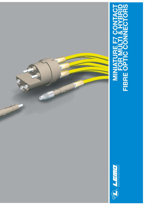


MINIATURE F7 CONTACT FOR MULTI & HYBRID FIBRE OPTIC CONNECTORS
※レモコネクタはモジュール方式のため、共通部品を組み合せることにより様々なコネクタに変えることができます。このため、カタログに掲載されている写真や図は、色、形状などが実物とは微妙に異なっている場合や、写真撮影の方向が一定していない場合がございます。ご注意いただきますようお願いいたします。
このカタログについて
| ドキュメント名 | F7光コンタクト |
|---|---|
| ドキュメント種別 | 製品カタログ |
| ファイルサイズ | 1.3Mb |
| 登録カテゴリ | |
| 取り扱い企業 | レモジャパン株式会社 (この企業の取り扱いカタログ一覧) |
この企業の関連カタログ


このカタログの内容
Page1
® ® MINIATURE F7 CONTACT
Electronic & Fibre Optic Connectors FOR MULTI & HYBRID
FIBRE OPTIC CONNECTORS
Page2
® ®
MINIATURE FIBRE-OPTIC F7 CONTACT FOR MULTIFIBRE OR MIXED OPTICAL/ELECTRICAL OF THE 1K-5K
AND 1B-5B SERIES
In addition to the existing F2 fibre optic contact shown in our catalogue of Fibre-Optic connectors No 5, the B and K
series can now also be fitted with the new miniature F7 contact. The main benefits of using this contact are:
– Reduced size allowing increased contact density. As an example, a 4-channel fibre optic connector is now possible in
series 3K/3B.
– Use of industry standard 1.25 mm diameter ferrule and polishing processes.
Contact design is based on the well-proven F2. Contacts fit onto buffered fibres or semitight jacket cables up to 2 mm in
diameter.
This brochure shows only a sample of the available models of connectors. Refer to our catalogue No 5 for more detailed
information of the full range of LEMO fibre optic connectors. Refer also to catalogue No 5 for accessories or tools spe-
cific to the electrical contacts used in hybrid connectors.
d Qu
ality
ie S
ISO 9001
Reg. No. 10472 - 03
5 Fibre Optic
Connectors
No reproduction or use without express permission of editorial or pictorial content, in any manner. Printed in Switzerland, November 2003
LEMO SA reserve the right at all times to modify and improve specifications without any notification. Pdf updated March 2011
2 www.lemo.com
Certif
m
ys
te
Page3
® ®
F7 Fibre Optic Contact
Introduction
The F7 type contact is designed to fit multi fibre connectors or mixed fibre optical/electrical connectors from 1B to 5B, 1K
to 5K series. The design is based on the well proven F2 contact.
Its main features are as follows:
– Ceramic ferrules diameter 1.25 mm
– Simple and fast polishing ensuring the physical contact of the fibre end face
– After mounting on the cable, the contact is very easily installed in the main connector insulator, the particular shape of
the contact body retains it in the insulator
– Single type of cable assembly, regardless of connector shell used
– The alignment tube can be easily removed in order to clean the fibre end face.
This contact makes it possible to use single fibre cables with single-mode or multi-mode fibres of the following sizes;
9/125, 50/125 and 62.5/125.
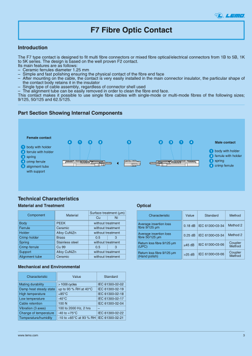
Part Section Showing Internal Components
Female contact
4 1 3 2 5 2 3 1 4 Male contact
1 body with holder
2 ferrule with holder 1 body with holder
3 spring 2 ferrule with holder
4 crimp ferrule 3 spring
5 alignment tube 4 crimp ferrule
with support
Technical Characteristics
Material and Treatment Optical
Surface treatment (µm)
Component Material Characteristic Value Standard Method
Cu Ni
Body PEEK without treatment Average insertion loss 0.18 dB IEC 61300-03-34 Method 2
Ferrule Ceramic without treatment fibre 9/125 µm
Holder Alloy CuNiZn without treatment Average insertion loss 0.25 dB IEC 61300-03-34 Method 2
Crimp holder Brass 0.5 3 fibre 50/125 µm
Spring Stainless steel without treatment Return loss fibre 9/125 µm ≥45 dB IEC 61300-03-06
Coupler
Crimp ferrule Cu 99 0.5 3 (UPC) Method
Support Alloy CuNiZn without treatment Return loss fibre 9/125 µm >25 dB IEC 61300-03-06
Coupler
Alignment tube Ceramic without treatment (Hand polish) Method
Mechanical and Environmental
Characteristic Value Standard
Mating durability > 1000 cycles IEC 61300-02-02
Damp heat steady state up to 93 % RH at 40°C IEC 61300-02-19
High temperature +85°C IEC 61300-02-18
Low temperature -40°C IEC 61300-02-17
Cable retention 100 N IEC 61300-02-04
Vibration (3 axes) 100 to 2000 Hz, 2 hrs –
Change of temperature -40 to +75°C IEC 61300-02-22
Temperature/humidity -10 to +65°C at 93 % RH IEC 61300-02-21
www.lemo.com 3
Page4
® ®
Part Number Example
F7 contacts are designed in 2 different lengths:
– the short version for 1B/K, 2B/K and 3B/K series, code E.
– the long version for 4B/K and 5B/K series, code L.
FFS F7 125 L C E 23
Model: FFS = Male contactPSS = Female contact
FO Contact type: F7 Cable ø: 23 = 0.25 to 2.0 mm
Fibre type: (page 3) Contact E = for 1B/K, 2B/K, 3B/KLength: L = for 4B/K, 5B/K
Body: L = PEEK Ferrule material:
C = Zirconia ceramic
FFS.F7.125.LCE23 = Male F7 type fibre optic contact, ferrule bore diameter of 125 µm, PEEK body, Zirconia ceramic
ferrule, contact length for 1B/K, 2B/K or 3B/K series, for cable with diameter max = 2.0 mm.
Model - FO Contact Type
FFS.F7 Male F7 Fibre Optic Contact
~ L Reference Dimensions (mm)
Model Series L
FFS.F7 1B, 1K, 2B, 2K, 3B, 3K 25.8
FFS.F7 4B, 4K, 5B, 5K 32.8
PSS.F7 Female F7 Fibre Optic Contact
~L 8.2 Reference Dimensions (mm)
Model Series L
PSS.F7 1B, 1K, 2B, 2K, 3B, 3K 25.8
PSS.F7 4B, 4K, 5B, 5K 32.8
4 www.lemo.com
ø 3.3
ø 3.3
ø 1.25
ø 1.25
Page5
® ®
Fibre Type
The choice of the ferrule hole diameter is dependent upon the fibre cladding size. LEMO offers a range of ferrule hole
diameters to suit the users’ specific requirements.
Reference ø Core/Cladding Ferrule hole 1)
(µm) diameter (µm) Note
125 125 ●
9/125
126 50/125 126 ●
62.5/125
128 128 ●
● First choice alternative ● Special order alternative
Accessories
PSS Alignment device for F7 fibre optic contact
8.2
Part number
PSS.F7.290.NZZ
Note: Alignment device should be ordered as replacement item.
FGG-EGG Insulators
Insulators for 1B-5B and 1K-5K series vary according to
the fibre optic contact type. For the new F7 contact insu-
lators are:
male female
FO Contact Insulator part number
Type F7 Male contact Female contact
1B/1K 92A FGG.1B.302.FL EGG.1B.402.FL
03A FGG.2B.302.FL EGG.2B.402.FL
2B/2K
93B FGG.2B.324.FL EGG.2B.424.FL
03C FGG.3B.304.FL EGG.3B.404.FL
3B/3K
95B FGG.3B.344.FL EGG.3B.444.FL
03G FGG.4B.308.FL EGG.4B.408.FL
4B/4K 03H FGG.4B.309.FL EGG.4B.409.FL
97B FGG.4B.362.FL EGG.4B.462.FL
03Q FGG.5B.316.FL EGG.5B.416.FL
5B/5K
03V FGG.5B.321.FL EGG.5B.421.FL
www.lemo.com 5
ø 3.2
Page6
® ®
1K-5K Series
The new F7 fibre optic contact has been designed to work in the 1K-5K series.
The main features of these series are as follows:
– Security of the LEMO Push-Pull self-latching system
– Specially designed for outdoors applications. All these models are waterproof when mated and reach a protection
index of IP 66-IP 68, according to the IEC 60529 standard
– Protection against accidental contamination or damage to the fibre end face because the ferrules are recessed within
the connector shell
– The alignment key (G, A…F, L and R) ensures excellent repeatability of performance during frequent matings
– A choice of configurations of multi fibre or mixed optical/electrical contacts
– The new miniature F7 contact allows hybrid configuration in the 1K series and multi fibre up to 21 channels in the 5K
series.
The 1K-5K series consists of ten models which will accept outer cable diameters ranging from 2.6 mm to 23.5 mm.
Interconnections
Straight plug Free socket Fixed sockets
FGG PHG
EGG
Fixed plugs Fixed sockets
EEG*
FXG*
PKG*
EBG*
FMG*
PEG* EDG*
Model Description
EBG Fixed socket with square flange, FGG Straight plug, key (G) or keys PHG Free socket, key (G) or keys
key (G) or keys (A…F, L and R), (A…F, L and R), cable adapter (A…F, L and R), cable adapter
four holes fixing and nut for fitting a bend relief and nut for fitting a bend relief
EDG Fixed socket with square flange, FMG Fixed plug with round flange, four holes PKG Fixed socket, nut fixing,
key (G) or keys (A…F, L and R), fixing, key (G) or keys (A…F, L and R), key (G) or keys (A…F, L and R),
protruding shell and earthing tag, cable adapter and nut for fitting a bend relief cable adapter and nut for fitting a bend relief
screw fixing FXG Fixed plug with round flange, four holes
EEG Fixed socket, nut fixing, fixing, key (G) or keys (A…F, L and R)
key (G) or keys (A…F, L and R) PEG Fixed socket, nut fixing, key (G)
(back panel mounting) or keys (A…F, L and R), cable adapter
EGG Fixed socket, nut fixing, and nut for fitting a bend relief * Not show in this catalogue.
key (G) or keys (A…F, L and R) (back panel mounting) Refer to our catalogue No 5.
Certain models and certain key-ways may not be available in all series. Please consult us.
6 www.lemo.com
Page7
® ®
Part Number Example
FGG 3K 03C C L A T 76 Z Variant: see note 1)
Model: (see examples below) Cable ø: (page 9)
Series: (see examples below) Cable fixing type:T = cable adapter
Type: (page 8) LV Contact Type: (page 9)
Housing: (C = chrome plated brass) Insulator: L = PEEK
FGG.3K.03C.CLAT76Z = Straight plug with key (G), 3K series, multi-fibre type to accept 4 F7 type fibre optic contacts,
chrome-plated brass housing, PEEK insulator, cable fixing type T for 7.5 mm diameter cable, and nut for fitting a bend
relief.
Connectors are delivered without fibre optic contacts. F7 fibre optic contacts must be ordered separately accor-
ding to size and type of fibre (see pages 1 to 3).
Note: 1) The «Variant» position in the reference is used to indicate the presence of a collet nut for fitting the bend relief. The bend relief must be ordered
separately.
Sample Models
FGG Straight plug, key (G) or keys (A…F, L and R),
cable adapter and nut for fitting a bend relief
Reference Dimensions (mm)
Model Series A L M S2
FGG 1K 13 92 78.0 9
FGG 2K 16 101 85.0 12
FGG 3K 19 109 89.0 15
FGG 4K 25 131 110.5 19
FGG 5K 38 160 135.0 30
�
Note: The overall length dimension is with Desmopan bend relief
PHG Free socket, key (G) or keys (A…F, L and R),
cable adapter and nut for fitting a bend relief
Reference Dimensions (mm)
Model Series A L S2
�
PHG 1K 15 95.0 9
PHG 2K 19 103.0 12
PHG 3K 23 113.0 15
PHG 4K 29 135.5 19
PHG 5K 42 164.0 30
Note: The overall length dimension is with Desmopan bend relief
EGG Fixed socket, nut fixing, key (G)
or keys (A…F, L and R)
Reference Dimensions (mm)
1)
Model Series A B e E L max M S1 S3
F1 F2
EGG 1K 20 21.5 M16x1.0 9 31.0 41.0 4.5 14.5 19
EGG 2K 25 27.0 M20x1.0 9 31.0 41.0 5.0 18.5 24
EGG 3K 31 34.0 M24x1.0 11 35.5 42.5 6.0 22.5 30
EGG 4K 37 40.5 M30x1.0 9 37.0 41.0 6.5 28.5 36
EGG 5K 55 54.0 M45x1.5 10 40.5 42.0 9.0 42.5 –
Note: 1) The overall length (L) may vary depending upon the type of
electrical LV or fibre optic contact fitted.
www.lemo.com 7
Page8
® ®
1B-5B Series
The new F7 fibre optic contact has been designed to work in the 1B-5B series.
The main features of these series are as follows:
– Security of the LEMO Push-Pull self-latching system
– Protection against accidental contamination or damage to the fibre end face because the ferrules are recessed within
the connector shell
– The alignment key (G, A…L, Y and R) ensures excellent repeatability of performance during frequent matings
– A choice of configurations of multi fibre or mixed optical/electrical contacts
– The new miniature F7 contact allows hybrid configuration in the 1B series and multi fibre up to 21 channels in the 5B
series.
The 1B-5B series consist of fifteen models. The possible outer cable diameters range from 2.1 to 25 mm.
Interconnections
Straight plugs Free sockets Fixed sockets Fixed sockets
FGG
EGG
PHG
PKG*
FGG*
ECG*
PHG*
PFG*
FNG* EHG*
Plastic housing models
Straight plugs Fixed sockets
FGG*
ENG*
FGY*
ENY*
FGY*
Model Description
ECG Fixed socket, with two nuts, FGG Straight plug, key (G or J), cable collet, PHG Free socket, key (G) or keys
key (G) or keys (A…L and R), PEEK outer shell (A…L) and cable collet and nut
(back panel mounting) FGY Straight plug, keys (Y), cable collet for fitting a bend relief
EGG Fixed socket, nut fixing, and PSU or PPSU outer shell PKG Fixed socket, nut fixing, key (G)
key (G) or keys (A…L and R) FGY Straight plug, keys (Y), cable collet or keys (A…L and R) and cable collet
EHG Fixed socket, nut fixing, key (G) and PSU or PPSU outer shell
or keys (A…L and R) with visible shell and nut for fitting a bend relief
ENG Fixed socket with grounding tab, FNG Straight plug, key (G) or keys
nut fixing, key (G or J), PEEK outer shell (A…L and R) and cable collet
ENY Fixed socket with grounding tab, nut with lanyard release
fixing, keys (Y), PSU or PPSU outer shell PFG Fixed socket, with two nuts,
FGG Straight plug, key (G) or keys key (G) or keys (A…L and R)
(A…L and R) and cable collet and cable collet (back panel mounting)
FGG Straight plug, key (G) or keys (A…L) PHG Free socket, key (G) * Not show in this catalogue.
cable collet and nut for fitting a bend relief or keys (A…L and R) and cable collet Refer to our catalogue No 5.
Certain models and certain key-ways may not be available in all series. Please consult us.
8 www.lemo.com
Page9
® ®
Part Number Example
FGG 2B 93B C L A D 72 Z Variant: see note 1)
Model: (see examples below) Cable ø: (page 9)
Series: (see examples below) Collet type: (page 9)
Type: (page 8) LV contact type: (page 9)
Housing: (C = chrome plated brass) Insulator: L = PEEK
FGG.2B.93B.CLAD72Z = Straight plug with key (G), 2B series, mixed type to accept 2 F7 fibre optic contact and 4 low
voltage electrical contacts, chrome-plated brass housing, PEEK insulator, 4 male solder electrical contacts, type D collet
system to suit a 7.0 to 6.1 mm diameter cable, and a nut for fitting a bend relief.
Connectors are delivered without fibre optic contacts. F7 fibre optic contacts must be ordered separately accor-
ding to size and type of fibre (see pages 1 to 3).
Note: 1) The «Variant» position in the reference is used to indicate the presence of a collet nut for fitting the bend relief. The bend relief must be ordered
separately.
Sample Models
FGG Straight plug, key (G) or keys
(A…L and R) and cable collet
Reference Dimensions (mm)
Model Series A L M S1 S2
FGG1) 1B 12 722) 612) 10 9
FGG 2B 15 50 38 13 12
FGG 3B 18 58 43 15 14
FGG 4B 25 75 57 21 20
FGG 5B 35 103 78 31 30
1)
� � Note: Models can be delivered only with «T» type of cable adapter
and nut for fitting a bend relief.
2) Lengths include the bend relief.
PHG Free socket, key (G) or keys (A…L and R)
and cable collet
Reference Dimensions (mm)
Model Series A L S1 S2
PHG1) 1B 12.5 69.52) 10 9
~L
PHG 2B 16.5 47.0 13 12
PHG 3B 19.0 56.0 15 14
PHG 4B 24.4 73.0 21 20
PHG 5B 34.2 99.0 31 30
S 2 S 1 Note: 1) Models can be delivered only with «T» type of cable adapter
and nut for fitting a bend relief.
2) Lengths include the bend relief.
EGG Fixed socket, nut fixing, key (G)
or keys (A…L and R)
L max
S 3 M Reference Dimensions (mm)
1)
Model Series A B e E L max M S1 S3F1 F2
EGG 1B 14 16 M12x1 7.5 27.0 37.0 1.5 10.5 14
EGG 2B 18 19.2 M15x1 8.5 27.0 37.0 1.8 13.5 17
EGG 3B 22 25.0 M18x1 11.5 30.0 37.0 2.0 16.5 22
EGG 4B 28 34.0 M25x1 12.0 34.5 38.5 2.5 23.5 30
E max S 1 EGG 5B 40 40.0 M35x1 11.0 36.5 38.0 3.0 33.5 –
Note: 1) The overall length (L) may vary depending upon the type of
electrical LV or fibre optic contact fitted.
www.lemo.com 9
ø B
e
ø A
ø A
Page10
® ®
Types
Multi fibre and Mixed fibre optic (F7 contact) + LV
Low Voltage contact
Contact Solder Crimp
type contact contact
Reference
FO Contact
Male solder contacts Female solder contacts Type
F7
Male crimp contacts Female crimp contacts
1B
92A 1 2 0.9 ● ● 0.90 1.50 1.20 1.80 7.0
1K
2B 03A 2 – – – – – – – – –
2K
1 4 4 1
93B 2 4 0.7 ● ● 0.85 1.20 0.85 1.25 6.02 3 3 2
3B
3K 03C 4 – – – – – – – – –
1 1
4 2
2 4 95B 4 4 0.9 ● ● 1.20 1.05 1.00 0.80 8.0
3 3
4B
4K 03G 8 – – – – – – – – –
03H 9 – – – – – – – – –
97B 6 2 1.6 ● ● 1.20 1.30 1.30 1.05 13
5B
5K 03Q 16 – – – – – – – – –
03V 21 – – – – – – – – –
Note: 1) Test voltage
Test voltage (Ue): Operating voltage (Us):
(measured according to the IEC 60512-2 test 4a standard). It is proposed according to the following ratio: Us = Ue
3
It corresponds to 75% of the mean breakdown voltage. Caution:
Test voltage is applied at 500 V/s and the test duration is For a number of applications, safety requirements for
one minute. electrical appliances are more severe with regard to
operating voltage.
This test has been carried out with a mated plug and
receptacle, with power supply only on the plug end.
10 www.lemo.com
ø A ø A
Fibre optic No
Contact No
ø A (mm)
Solder
Crimp
Test voltage (kV rms)1)
Contact-contact
Test voltage (kV rms)1)
Contact-shell
Test voltage (kV rms)1)
Contact-contact
Test voltage (kV rms)1)
Contact-shell
Rated current (A)
Page11
® ®
Electrical Contact
Contact for plug, socket, and fixed socket
Ref. Contact type
A male solder
C male crimp
L female solder
M female crimp
Z no contact
Collets (K and B series)
T type cable adapter D and M type collets
Reference Cable ø Reference Cable ø
Bend relief to be used 1)
Type ø max. min. Type ø max. min.
1B T 36 3.5 2.6 GMA.1B.030.D● M 31 3.2 > 2.2T 46 4.5 3.6 GMA.1B.040.D● 2B D 42 4.2 > 3.21K D 52 5.2 > 4.2
T 46 4.5 3.6 GMA.2B.040.D● D 62 6.2 > 5.2
2K T 56 5.5 4.6 GMA.2B.050.D● D 72 7.2 > 6.2
T 66 6.5 5.6 GMA.2B.060.D● D 82 8.2 > 7.2
T 46 4.5 3.6 GMA.2B.040.D D 92 9.2 > 8.2●
3K T 56 5.5 4.6 GMA.2B.050.D● M 52 5.2 > 4.2
T 66 6.5 5.6 GMA.2B.060.D● 3B D 62 6.2 4.9
T 76 7.5 6.6 GMA.3B.070.D● D 72 7.7 > 6.2
T 86 8.5 7.6 GMA.3B.080.D● D 92 9.2 > 7.7
T 91 9.0 8.1 GMA.3B.080.D● D 10 10.7 > 9.2
T 46 4.5 3.6 GMA.2B.040.D D 12 11.9 > 10.7●
4K T 56 5.5 4.6 GMA.2B.050.D● M 62 6.0 5.1
T 66 6.5 5.6 GMA.2B.060.D● 4B M 72 7.0 6.1
T 76 7.5 6.6 GMA.3B.070.D● M 82 8.0 7.1
T 86 8.5 7.6 GMA.3B.080.D● M 92 9.0 8.1
T 96 9.5 8.6 GMA.4B.010.D● 2) D 10 10.5 9.1
T 11 11.5 10.6 GMA.4B.011.D● D 12 12.0 10.6
T 13 13.5 12.6 GMA.4B.013.D● D 13 13.5 12.1
T 61 6.0 5.1 GMA.2B.057.R D 15 15.0 13.6●
5K T 71 7.0 6.1 GMA.3B.060.D● D 11 11.5 9.6
T 81 8.0 7.1 GMA.3B.070.D● 5B D 13 13.5 11.6
T 91 9.0 8.1 GMA.3B.080.D● D 15 15.5 13.6
T 96 9.5 8.6 GMA.4B.010.D● 2) D 17 17.5 15.6
T 10 10.5 9.6 GMA.4B.010.D● D 19 19.5 17.6
T 11 11.5 10.6 GMA.4B.011.D● D 21 21.5 19.6
T 12 12.5 11.6 GMA.4B.012.D● D 23 23.5 21.6
T 13 13.5 12.6 GMA.4B.013.D● D 25 25.0 23.6
T 14 14.5 13.6 GMA.4B.013.D● Note:
T 15 15.5 14.6 heat-shrink tube 3) 1) The bend relief is to be ordered separately.
T 16 16.5 15.6 heat-shrink tube 2) Add a short piece of heat-shrink tubing under the bend relief.
3) The heat-shrink tube is supplied.
T 17 17.5 16.6 heat-shrink tube
T 18 18.5 17.6 heat-shrink tube All dimensions are in millimeters.
T 19 19.5 18.6 heat-shrink tube
T 20 20.5 19.6 heat-shrink tube
T 21 21.5 20.6 heat-shrink tube
T 22 22.5 21.6 heat-shrink tube
T 23 23.5 22.6 heat-shrink tube
www.lemo.com 1 1
Page12
® ®
Fibre Optic Tooling
We offer a complete range of tools for fibre optic connector cable assembly.
Some tools are specific to each fibre optic contact type. When selecting necessary tooling, make sure you identify
correctly the contact type used in the selected product.
DRV Complete workstation for fibre optic contact
Description
Comprehensive range of tools for terminating both single-
mode and multi-mode fibres. Includes specific tools for F7
fibre optic contacts. Detachable termination case lid for
use as polishing platform during field termination.
Rugged but aesthetically pleasing termination case which
is ideal for field use or in-house terminations. Curing oven
and inspection microscope should be ordered separately.
Part number
DRV.91.CF7.PN
Workstation Contents
18
Part Number Description
WST.BT.175.55PT Plastic box 1 1
25
WST.BR.150.8AC Tweezers 1 2 17
WST.CH.252.5SR Lint-free Cloth 1 3 16 26
WST.CS.125.CE Kevlar cutters 1 4 11
WST.CO.020.52 Cotton bud (sachet of 20 pcs) 1 5
WST.DS.290.PT Alcohol dispenser (supplied empty) 1 6 3 29
DCC.91.307.5LA Extraction tool for F7 contact 1 7 30 31
DCS.F7.035.PN Alignment device tool 1 8
DCS.91.G90.6E125 Microscope adapter for F7 contacts 1 9
WST.ME.354.8R Epoxy mixer and pad 1 10
DOC.FO.CF7.0000 Terminating instructions for F7 contacts 1 11
WST.OU.135.10SZ Fibre scribe 1 12
DCS.91.D01.LC Polishing tool for F7 contacts 1 13
WST.OU.452.5MN Large cable stripper 1 14
WST.PA.105.5525 Cleaning tissues 1 15
WST.PA.012.AOJ Lapping film 12µm (yellow) 20 16
WST.PA.005.AOM Lapping film 5µm (brown) 20 17 7 8
WST.PA.001.DIL Lapping film 1µm (lavander) diamond 5 18
WST.PN.210.AS Armoured cable cutter 1 19
26 19
WST.PN.145.AR Cable cutter 1 20
27 23
WST.PN.103.0PG Outer jacket stripper 1 21
5 24
WST.PN.203.CR Buffer coating stripping tool 1 22
1 22WST.PN.102.3CR Primary coat stripper 1 23
10
DPE.99.003.1K Crimp tool 1 24 15
20
WST.PL.322.5PT Polishing platform 1 25 28
WST.RE.353.EPO Epoxy resin + safety instructions 10 26 13 9
WST.SE.305.8PH Syringe with needle # 19 & # 20 10 27 6 21
WST.TU.193.LN Fibre shield for F7 contacts 4 28 14
WST.RG.150.AZ Steel rule 6’’ (152 mm) 1 29 4 2
WST.SY.135.PA Fibre length marking pen 1 30 12
WST.CS.155.AZ Scissors 1 31
Note: The interior of the case is fitted with pre-formed plastic foam to
provide secure storage of the tools.
12 www.lemo.com
Quantity
Number
Page13
® ®
DPE Crimping tool for F7 fibre optic contact
Description
Crimping tool for capturing KEVLAR® strand on contact
body.
3.1
Part number
DPE.99.003.1K 1)
Note: 1) Included in the LEMO F7 workstation.
WST Epoxy curing oven
Description
Oven for assisting in curing epoxy.
Part number Voltage
WST.FR.220.VA 220 volts
WST.FR.110.VA 110 volts
DCS Polishing tool for fibre optic contacts
Description
Precision tool for polishing terminated fibre optic contacts
with 1.25 mm ferrule.
Part number
DCS.91.D01.LC 1)
Note: 1) Included in the LEMO F7 workstation.
WST Fibre Inspection Microscope
Description
Microscope to assist in viewing termination operations
and verifying fibre end finish. Zoom with 200 ➞ 400 x
magnification.
See adaptor below.
Part number
WST.FB.G00.301
DCS Microscope adaptor for fibre optic contacts
Description
Adaptor for final inspection of fibre optic contacts with
1.25 mm ferrule.
To be used with microscope WST.FB.G00.301.
Part number
DCS.91.G90.6E125 1)
Note: 1) Included in the LEMO F7 workstation.
www.lemo.com 13
2.7
Page14
® ®
DCC Extractor for F7 fibre optic contact
Description
Manual tool for the extraction of the F7 contact.
Part number
DCC.91.307.5LA 1)
Note: 1) Included in the LEMO F7 workstation.
DCS F7 contact alignment device tool
Description
Simple tool with two threaded end for installation/extraction
of the F7 contact alignment device.
Part number
DCS.F7.035.PN 1)
Note: 1) Included in the LEMO F7 workstation.
WST Fibre shield for F7 fibre optic contact
Description
To protect ferrule when curing epoxy.
Part number
WST.TU.193.LN 1)
Note: 1) Included in the LEMO F7 workstation.
Cable Termination
Detailed instructions for terminating single fibre cables with LEMO F7 fibre optic contacts are given in the reference
manual DOC.FO.CF7.0000 supplied with the complete termination workstation (see page 10). After termination contacts
shall be introduced in the main insulator as shown below. For purpose of cleaning they can also be removed.
Installation of F7 contact and alignment device
Insertion For female contacts, the alignment device shall be clip-
ped onto the fibre optic contacts which is already fitted
The male fibre optic contact terminated on the cable must into female insulator. This procedure is performed using
be inserted into the connector insulator from the back end the tool, reference DCS.F7.035.PN.
until it comes to a stop. Make sure that the contact is cor- The alignment device shall be first installed onto threaded
rectly positioned into the inner antirotation key. Key is in end of the tool (step 3). Then clip the adapter (step 4),
line with the red dot on the rear of the contact (step 1). unscrew and remove the tool (step 5).
Check that the contact is correctly retained by gently pul-
ling on it (step 2). Extraction of alignment device
Screw the threaded end of the tool reference
1) DCS.F7.035.PN (step 1) onto the alignment device.
Pull out strongly (step 2).
2) 1)
3) 2)
4) Extraction of F7 contact
Possible only for fixed socket, using the manual tool
DCC.91.307.5LA. Shall be made with great care.
5)
Note: The life time installation of the alignment device is minimum 300
cycles.
14 www.lemo.com
Page15
® ®
www.lemo.com 15
Page16
LEMO HEADQUARTERS
SWITZERLAND
LEMO SA
Chemin des Champs-Courbes 28 - P.O. Box 194 - CH-1024 Ecublens
Tel. (+41 21) 695 16 00 - Fax (+41 21) 695 16 02 - e-mail: info@lemo.com
LEMO SUBSIDIARIES
AUSTRIA NETHERLANDS / BELGIUM
LEMO Elektronik GesmbH LEMO Connectors Benelux
Lemböckgasse 49/E6-3 De Trompet 2108
1230 Wien 1967 DC Heemskerk
Tel: (+43 1) 914 23 20 0 Tel. (+31) 251 25 78 20
Fax:(+43 1) 914 23 20 11 Fax (+31) 251 25 78 21
sales@lemo.at info@lemo.nl
CHINA NORWAY / ICELAND
LEMO Trading (Shanghai) Co., Ltd LEMO Norway A/S
LEMO Electronics (Shanghai) Co., Ltd Stanseveien 6B
5th Floor, Block 6, City of ELITE, 0975 Oslo
1000 Jinhai Road, Pudong Tel: (+47) 22 91 70 40
Shanghai, China 201206 Fax: (+47) 22 91 70 41
Tel: (+86 21) 5899 7721 info-no@lemo.com
Fax: (+86 21) 5899 7727
cn.sales@lemo.com SINGAPORE
LEMO Asia Pte Ltd
DENMARK 4 Leng Kee Road,
LEMO Denmark A/S #06-09 SiS Building
Gammel Mosevej 46 Singapore 159088
2820 Gentofte Tel: (+65) 6476 0672
Tel: (+45) 45 20 44 00 Fax: (+65) 6474 0672
Fax: (+45) 45 20 44 01 sg.sales@lemo.com
info-dk@lemo.com
SPAIN / PORTUGAL
FRANCE IBERLEMO S.A.
LEMO France Sàrl Brasil, 45, 08402 Granollers
24/28 Avenue Graham Bell Barcelona
Bâtiment Balthus 4 Tel: (+34 93) 860 44 20
Bussy Saint Georges Fax: (+34 93) 879 10 77
77607 Marne la Vallée Cedex 3 info-es@lemo.com
Tel: (+33 1) 60 94 60 94
Fax: (+33 1) 60 94 60 90 Madrid Office
info-fr@lemo.com Antonio López, 96, 28019 MadridTel: (+34 91) 469 99 19
GERMANY Fax: (+34 91) 469 99 59
LEMO Elektronik GmbH
Hanns-Schwindt-Str. 6 SWEDEN / FINLAND
81829 München LEMO Nordic AB
Tel: (+49 89) 42 77 03 Mariehällsvägen 39A
Fax: (+49 89) 420 21 92 168 65 Bromma
info@lemo.de Tel: (+46 8) 635 60 60Fax: (+46 8) 635 60 61
HONG KONG info-se@lemo.com
LEMO Hong Kong Ltd
Room 33. 7th Floor SWITZERLAND
HITEC, 1 Trademart Drive LEMO Verkauf AG
Kowloon Bay - Hong Kong Grundstrasse 22 B
Tel: (+852) 2174 0468 6343 Rotkreuz
Fax: (+852) 2174 0492 Tel: (+41 41) 790 49 40
hk.sales@lemo.com Fax: (+41 41) 790 49 43ch.sales@lemo.com
HUNGARY
REDEL Elektronika Kft UNITED KINGDOM
Vágóhíd u. 26 LEMO UK Ltd
1201 Budapest XX. 12-20 North Street
Tel: (+36 1) 421 47 10 Worthing
Fax: (+36 1) 421 47 57 West Sussex, BN11 1DU
info-hu@lemo.com Tel: (+44 1903) 23 45 43Fax: (+44 1903) 20 62 31
ITALY lemouk@lemo.com
LEMO Italia srl
Viale Lunigiana 25 USA
20125 Milano LEMO USA Inc
Tel: (+39 02) 66 71 10 46 P.O. Box 2408
Fax: (+39 02) 66 71 10 66 Rohnert Park, CA 94927-2408
sales.it@lemo.com Tel: (+1 707) 578 88 11(+1 800) 444 53 66
JAPAN Fax:(+1 707) 578 08 69
LEMO Japan Ltd info@lemousa.com
4-10-3, Takaido Higashi,
Suginami-ku, Tokyo, 168-0072
Tel: (+81 3) 53 44 39 33
Fax: (+81 3) 53 44 39 35
lemoinfo@lemo.co.jp
LEMO DISTRIBUTORS
AUSTRALIA, BRAZIL, CANADA, CZECH REPUBLIC, GREECE, INDIA, ISRAEL,
NEW ZEALAND, POLAND, RUSSIA, SOUTH AFRICA, SOUTH KOREA, TAIWAN,
TURKEY, UKRAINE
www.lemo.com
© CAT.F7.LEN.P1103