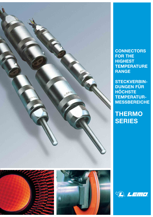


CONNECTORS FOR THE HIGHEST TEMPERATURE RANGE
STECKVERBINDUNGEN FÜR
HÖCHSTE
TEMPERATURMESSBEREICHE
※レモコネクタはモジュール方式のため、共通部品を組み合せることにより様々なコネクタに変えることができます。このため、カタログに掲載されている写真や図は、色、形状などが実物とは微妙に異なっている場合や、写真撮影の方向が一定していない場合がございます。ご注意いただきますようお願いいたします。
このカタログについて
| ドキュメント名 | 各種熱電対コネクタ |
|---|---|
| ドキュメント種別 | 製品カタログ |
| ファイルサイズ | 5.7Mb |
| 登録カテゴリ | |
| 取り扱い企業 | レモジャパン株式会社 (この企業の取り扱いカタログ一覧) |
この企業の関連カタログ


このカタログの内容
Page1
CONNECTORS
FOR THE
HIGHEST
TEMPERATURE
RANGE
STECKVERBIN-
DUNGEN FÜR
HÖCHSTE
TEMPERATUR-
MESSBEREICHE
THERMO
SERIES
Page2
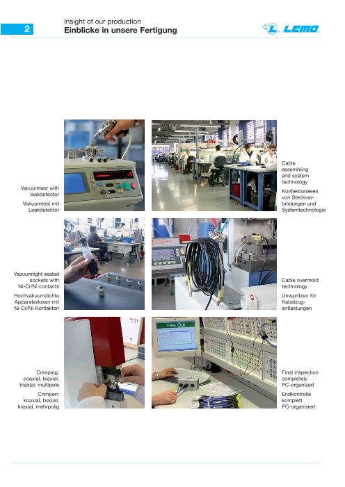
Insight of our production
2 Einblicke in unsere Fertigung
Cable
assembling
and system
technology
Vacuumtest with Konfektionieren
leakdetector von Steckver-
Vakuumtest mit bindungen und
Leakdetektor Systemtechnologie
Vacuumtight sealed
sockets with Cable overmold
Ni-Cr/Ni contacts technology
Hochvakuumdichte Umspritzen für
Apparatedosen mit Kabelzug-
Ni-Cr/Ni-Kontakten entlastungen
Crimping: Final inspection
coaxial, biaxial, completely
triaxial, multipole PC-organized
Crimpen: Endkontrolle
koaxial, biaxial, komplett
triaxial, mehrpolig PC-organisiert
Page3
Contents
Inhaltsverzeichnis 3
Serie / Series Seite / Page
Technische Information / Technical information 4 – 7
Tabelle / Table / DIN-Information 8 – 9
Bestellinformation / Order information S 10
Spannzangen-Übersicht / Collets table S 11 – 13
Bauform / Model S 14 – 17
TH-Kontaktfiguration / TH-Contact figuration S + E 18
TH-Spannzangen u. ISO / TH-Collets and insulators S 19 – 25
Bestellinformation / Order information E 26
Spannzangen-Übersicht / Collets table E 27
Bauform / Model E 28 – 30
TH-Spannzangen u. ISO / TH-Collets and insulators E 31
Bestellinformation / Order information B 32
Spannzangen-Übersicht / Collets table B 33
Bauform / Model B 34 – 36
TH-Kontaktfiguration / TH-Contact figuration B 37
TH-Spannzangen u. ISO / TH-Collets and insulators B 38 – 40
Konfektionierungen / Cable assembly 41
Crimptechnik S/E Serie / Crimptechnique S/E Series S + E 42 – 46
Crimptechnik B/K Serie / Crimptechnique B/K Series B + K 47 – 50
Katalogübersicht / Catalog summary 51
Page4
Technical information
4 Technische Information
Messwiderstande,Widerstandsther- Measure resistances, resistance ther-
mometer, Ausgleichsleitungen, Mantel- mometers, compensation cables, insu-
leitungen und vor allen Dingen Mantel- lated cables and particularly insulated
Thermoelemente müssen für den indus- thermocouples must be fitted with a
triellen Einsatz mit einer geeigneten suitable connector for the industrial use.
Steckverbindung versehen werden.
The thermovoltage is measured in mV
Das Messen der Thermospannung er- and μV. The LEMO connector is the
folgt in mV und μV. Für diesen Mess- ideal construction part for this techno-
bereich ist die LEMO-Steckverbindung logy.
das ideale Bauteil.
Mantel-Thermoelemente, Jacket thermocouples,
Aufbau und Funktion construction and function
Miniatur-Mantel-Thermoelemente beste- Miniature jacket thermocouples consist
hen aus einem Thermopaar, eingebettet of a thermo pair fitted in an high tempe-
in einer hochtemperaturfesten kerami- rature ceramic insulation material coat-
schen Isolationsschicht, umgeben von ed with a metallic jacket, saved against
einem Metallmantel, der als Schutz mechanical and chemical effects.
gegen mechanische und chemische
Einwirkungen dient.
Der Aufbau und die Funktion von Man- The construction and the function of the
tel-Thermoelementen ist bis hin zu thermocouples and the parts of the con-
Steckverbindungen in der DIN 4370, nector are normed in DIN 4370, 43721,
43721, I.E.C.584 1, 2 und 4, festgehal- I.E.C.584 1, 2 and 4.
ten.
Page5
Technical information
Technische Information 5
Die Auswahl des Adermaterials The part of the wire material will choosed
bestimmt den Temperaturbereich. the temperature range.
Mit TH-Thermoelementen sind Messun- The measurements of thermocouples is
gen zwischen - 250 und + 2200 °C between - 250 and + 2200 °C.
möglich. Die Entwicklung für neue The development of new materials is
Werkstoffe, seit der Einführung durch still moving since the introduction of
SEEBECK und PELTIR, ist noch immer SEEBECK and PELTIR.
in Bewegung.
The most used thermocouple is the part
Das gebräuchlichste Thermopaar ist die of Chromel-Alumel (type K). The tempe-
Ausführung Chromel-Alumel (Typ K). rature range is from - 200 to 1100 °C.
Der Einsatzbereich liegt bei - 200 bis With our LEMO connector we reached
1100 °C. In Verbindung mit unserer good thermoelectric characteristics. The
LEMO Steckverbindung erhält man hier thermoelectric power curve is nearly
gute thermoelektrische Eigenschaften, linear.
und der Thermo-Spannungsverlauf ist
fast linear.
Thermospannung (mV) Thermoelectric power (mV)
E.m.f. (mV)
80
70 68.783 mV
E
60
50 48.828 mV
K
42.283 mV 47.502 mV
40 J N
35.932 mV
C
30
18.842 mV
20 R
16.771 mV
S
10 12.426 mV
B
0
Temperatur (°C)
Steckverbindung und Connector and thermocouple
Thermoelement
In extreme cases the distance between
Die Entfernung zwischen der Meßstelle the measuring point and the gauge can
und dem Messgerät beträgt in extre- be several hundred meters.
men Fällen mehrere 100 m.
Page6
Technical information
6 Technische Information
Messaufbau Measurement assembly
Mantel- Ausgleichs- Meßgerät
thermo- leitung
element
-
+ mV
Steckverbindung Vergleichsstelle
Um eine einwandfreie Funktion der To guarantee a good function of the
Miniatur-Mantel-Thermoelemente zu insulated miniature thermocouples, the
gewährleisten, müssen die Anschluß- connection points must be tightly saved
stellen gegen Feuchtigkeit dicht abge- against humity. This sealing can be
schlossen werden. Dies geschieht made with plastic materials, especially
durch Vergießen mit Kunststoffen. Hier STYCAST which has a temperature
hat sich insbesondere das Vergußmate- variation from 73 to 177 °C.
rial STYCAST mit einem Temperatur-
bereich von 73 bis 177 °C, bewährt.
TH-Spannzangen mit Vergußstelle TH-collets with sealing point
Stycast
Page7
Technical information
Technische Information 7
Aus langen Erfahrungswerten geht her- During many years of experience, we
vor, daß bei den gebräuchlichsten can assert that LEMO contacts of high
Thermopaaren, wie z. B. Chromel- quality in the special golden version can
Alumel, die hochwertigen LEMO-Kon- be mounted on the most used thermo-
takte in der spezial vergoldeten Version couples, for example Chromel-Alumel.
eingesetzt werden können. An der At the connection point with the thermo-
Anschlußstelle mit dem Thermoele- couple material neutralizes the e.m.f.
mentmaterial hebt sich die EMK (elek- (electromagnetic force). This is only the
tromagnetische Kraft) vollständig auf. case, when the connector like an inter-
Dies ist aber nur der Fall, wenn die mediate piece in the thermoelectric wire
Steckverbindung als Zwischenstück in works. The system must be on a con-
der Thermoleitung dient und diese sich stant temperature level. Wherever we
wiederum auf einem gleichbleibenden don’t reach a thermal balance of the
Temperaturlevel befindet. Überall dort, connector, the contact should be from
wo ein thermisches Gleichgewicht der the same material as the thermocouple.
Steckverbindung nicht erreicht wird, See table thermoelement compensation
muß der Steckkontakt aus demselben cable.
Material, wie das der Thermoelemente,
gewählt werden. Siehe Tabelle Thermo- If you use connectors with thermo-
elemente-Ausgleichskabel. contacts, you must pay attention to the
assembly according to DIN 43711,
Bei der Verwendung von Steckverbin- A.N.S.I. MC 96.1.
dungen mit Thermokontakten ist auf
den richtigen Anschluß nach DIN 43711,
A.N.S.I. MC 96.1, zu achten.
Siehe Tabelle nach Farbcode und See following table code colours
+/- Einteilung. and +/- splitting.
Wir empfehlen nachstehendes We recommend following solder
Lötzinn: tin:
Bei der Verwendung von Lötzinn, Typ When you work with solder tin of type
HMP07, und der richtigen Löttemperatur HMP07 and the right soldering tempe-
(380 °C), ist eine leichte Verarbeitung rature (380 °C), an easy working and a
und ein homogener Anschluß gewähr- homogeneous connection can be
leistet. Entspricht laut Freistellung der guaranteed. According to release
ISO 14001. of ISO 14001.
Das Mantel-Thermoelement wird in der The jacket thermocouple will be usually
Regel an der Kupplung, Typ PCA.- - -, connected to the free socket of type
oder an der Apparatedose mit Zugent- PCA. - - - or to the receptacle with
lastung, Typ PSA. - - -, angeschlossen. cable collet type PSA. - - -.
Der Anschluß der Ausgleichsleitung The compensation cable is conse-
erolgt somit am Slecker mit der Push- quently fitted at the connector with
Pull-Verriegelung, Typ FFA. - - -. Push-Pull locking system,
type FFA. - - -.
Page8
+ – Table
8 + – Tabelle
Thermoelement Ausgleichskabel
Typ / Model Polung / Pole Material Polung / Pole Material
B + Platin, 30% Rodium + Cu-Legierung
– Platin, 6% Rodium – Cu
+ Nickel-Chrom + NiCr
E (Chromel)– Kupfer-Nickel – CuNi
(Konstantan)
+ Eisen + Fe
J – Kupfer-Nickel – CuNi
(Konstantan)
+ Nickel-Chrom + NiCr + Fe
K (Chromel)
– Nickel – Ni – CuNi
(Alumel)
+ Eisen + Fe
L – Kupfer-Nickel – CuNi
(Konstantan)
+ Nickel-Chrom-Silizium + NiCrSi + Cu
N (Nicrosil)
– Nickel-Silizium – NiSi – CuNi
(Nisil)
+ Platin, 13% Rodium + Cu
R – Platin – CuNi
+ Platin, 10% Rodium + Cu
S – Platin – CuNi
+ Kupfer + Cu
T – Kupfer-Nickel – CuNi
(Konstantan)
+ Kupfer + Cu
U – Kupfer-Nickel – CuNi
(Konstantan)
Page9
Farbcode Tabelle nach DIN 43714,
NFC 42.324, BS 1843 und ANSI MC 96.1 9
Die gebräuchlichsten Aus- The common compensation
gleichskabel (vor Dezember 1993) cables (before december 1993)
Typ Standards Mantel Seele + Seele –
Model (Sheath) (Wire +) (Wire –)
K NF + –
K DIN + –
K BS + –
K ANSI + –
J NF + –
L DIN + –
J BS + –
J ANSI + –
E NF + –
T NF + –
T DIN + –
S NF + –
Ab Dezember 1993 sind die unter- Different norms as NF C 42-324, DIN
schiedlichen Normen, NF C 42-324, DIN 43714 (except type no. L), BS 1843 and
43714 (ausgenommen Typ L) BS 1843 ANSI MC 96.1 are summarised in the
und ANSI MC 96.1 in den internationa- international standard IEC 584-3 and
len Standards IEC 584-3 und der DIN DIN 43722 since December 1993.
43722 zusammengefasst.
Typ Standards Mantel Seele + Seele –
Model (Sheath) (Wire +) (Wire –)
IEC 584-3
K DIN 43722 + –
IEC 584-3
J DIN 43722 + –
IEC 584-3
E DIN 43722 + –
IEC 584-3
T DIN 43722 + –
IEC 584-3
S DIN 43722 + –
Page10
Order information S Series standard
10 Bestellinformation S Serie Standard
Konstruktions-lnformation Constructions information
S Serie Standard S Series standard
6 2 3 1 4 5 8 7 1 7 6 5 4 2 8 3
Fixed socket Straight plug
1 Outer shell 5 Locking washer 1 Outer shell 5 Insulator
2 Earthing crown 6 Insulator 2 Latch sleeve 6 Male contact
3 Retaining ring 7 Male contact 3 Collet nut 7 Female contact
4 Hexagonal nut 8 Female contact 4 Centre-piece 8 Collet
Bestellbeispiele Part number example
Standardstecker, gerade Straight standard plug
FFA 0S 302 C L A L 32 Z N
Model (page 14 – 17) Bend relief and Color
Please see Unipole/Multipole catalogue
Size and Series (page 14 – 17) Collet nut for bend relief
Please see Unipole/Multipole catalogue
Contact figuration Collet-Ø
(page 18 + 41, 19 – 25) (page 11 – 13, 19 – 25)
Housing Collet Type
Please see Unipole/Multipole catalogue (page 11 – 13, 19 – 25)
Insulator Contact (page 18 + 41)
Please see Unipole/Multipole catalogue
Standardstecker gerade, Größe 0, S Serie Straight plug, size 0, S Series, 2 contacts,
mehrpolig (2 Kontakte), Außenkörper aus chromed brass shell, PEEK insulator, male and
Messing, Isolationsteil aus PEEK, männlicher female solder contact, collet 3,2 mm for shielded
und weiblicher Lötkontakt, Spannzange für cable.
geschirmtes Kabel, Durchmesser 3,2 mm.
Apparatedose Socket
ERA 2S 302 C L L
Variant
Model (page 14 – 17) Contact (page 18 + 41)
Size and Series (page 14 – 17) Insulator
Please see Unipole/Multipole catalogue
Contact figuration Housing
(page 18 + 41, 19 – 25) Please see Unipole/Multipole catalogue
Einbauapparatedose, Größe 2, S Serie, mehr- Fixed socket, size 2, S Series, 2 contacts, chro-
polig (2 Kontakte), Außenkörper aus Messing, med brass shell, PEEK insulator, female and
verchromt, Massekrone vernickelt, Isolationsteil male solder contact.
aus PEEK, männlicher und weiblicher Lötkontakt.
Page11
Collets table
Spannzangen-Übersicht 11
S Series – Size 0
S Serie – Größe 0
C = AG L = NG
K = Adapter to the next size
Reference Ø Collet Ø Cable
(mm) (mm) Part number Re- Part number Part number
Series collet marks adapter Collet nut
Model Ø ØA ØB max. min. 1) 2) 2)
C 17 1,7 — 1,6 1,3 FFA.0S.717.CN B
C 22 2,2 — 2,1 1,7 FFA.0S.722.CN B
C 27 2,7 — 2,6 2,2 FFA.0S.727.CN b
C 32 3,2 — 3,1 2,7 FFA.0S.732.CN b
C 37 3,7 3,2 3,6 3,0 FFA.0S.737.CN b
C 42 4,2 3,7 4,1 3,3 FFA.0S.742.CN b
C 44 4,4 3,7 4,3 3,5 FFA.0S.744.CN 4)b FFA.0S.133.LC
C 50 5,1 5,1 5,0 4,4 FFA.0S.750.CN 4)b FFA.0S.133.LC
K 47 4,7 — 4,6 3,8 FFA.1S.747.CN b FFA.0S.137.LCN FFA.1S.130.LC
K 52 5,2 — 5,1 4,3 FFA.1S.752.CN b FFA.0S.137.LCN FFA.1S.130.LC
K 57 5,7 — 5,6 4,8 FFA.1S.757.CN b FFA.0S.137.LCN FFA.1S.130.LC
K 62 6,2 5,2 6,1 5,3 FFA.1S.762.CN b FFA.0S.137.LCN FFA.1S.130.LC
K 66 6,6 5,5 6,5 5,9 FFA.1S.766.CN B FFA.0S.137.LCN FFA.1S.130.LC
K 68 0S 6,8 5,5 6,7 6,0 FFA.1S.768.CN b FFA.0S.137.LCN FFA.1S.130.LC
C 17 1,7 — 1,6 1,3 FLA.0S.717.CN 3)b
C 22 2,2 — 2,1 1,7 FLA.0S.722.CN 3)b
C 27 2,7 — 2,6 2,2 FLA.0S.727.CN 3)b
C 32 3,2 — 3,1 2,7 FLA.0S.732.CN 3)b
C 37 3,7 3,2 3,6 3,0 FLA.0S.737.CN 3)b
C 42 4,2 3,7 4,1 3,3 FLA.0S.742.CN 3)b
C 44 4,4 3,7 4,3 3,5 FLA.0S.744.CN 3)b
L 17 1,7 — 1,6 1,3 FFA.0S.717.LN b
L 22 2,2 — 2,1 1,8 FFA.0S.722.LN b
L 27 2,7 — 2,6 2,3 FFA.0S.727.LN b
L 32 3,2 — 3,1 2,8 FFA.0S.732.LN b
L 37 3,7 — 3,6 3,0 FFA.0S.737.LN b
L 42 4,2 — 4,1 3,3 FFA.0S.742.LN b
L 48 4,8 — 4,7 4,4 FFA.0S.748.LN 4)b FFA.0S.133.LC
1) Für Einzelbestellung der Spannzangen. 1) For individual orders of collets.
2) Für Einzelbestellung einer Spannzange der Type K benötigt man 2) For individual orders of a collet type K an adapter each is required as
je einen Adapter und eine Spannschraube (Bestell-Nr. siehe oben). well as a collet nut (part number is mentioned above).
3) Diese Spannzange paßt zu den Typen FLA, FFP und PCP. 3) This collet is used for the FLA, FFP and PCP models.
4) Diese Spannzangen können nicht in Bauformen mit Spannschrauben 4) These collets cannot be used for connector models with nut for fitting
für Knickschutztüllen verwendet werden. a bend relief.
b lieferbar b in stock
B auf Anfrage B on request
Ø B
Ø A
Ø A
Page12
Collets table
12 Spannzangen-Übersicht
S Series – Size 1
S Serie – Größe 1
C = AG L = NG
K = Adapter to the next size
Reference Ø Collet Ø Cable
(mm) (mm) Part number Re- Part number Part number
Series collet marks adapter Collet nut
Model Ø ØA ØB max. min. 1) 2) 2)
C 17 1,7 — 1,6 1,3 FFA.1S.717.CN B FFA.1S.130.LC
C 22 2,2 — 2,1 1,7 FFA.1S.722.CN b FFA.1S.130.LC
C 27 2,7 — 2,6 2,2 FFA.1S.727.CN b FFA.1S.130.LC
C 32 3,2 — 3,1 2,6 FFA.1S.732.CN b FFA.1S.130.LC
C 37 3,7 — 3,6 2,7 FFA.1S.737.CN b FFA.1S.130.LC
C 42 4,2 — 4,1 3,3 FFA.1S.742.CN b FFA.1S.130.LC
C 47 4,7 — 4,6 3,8 FFA.1S.747.CN b FFA.1S.130.LC
C 52 5,2 — 5,1 4,3 FFA.1S.752.CN b FFA.1S.130.LC
C 57 5,7 — 5,6 4,8 FFA.1S.757.CN b FFA.1S.130.LC
C 62 6,2 5,2 6,1 5,3 FFA.1S.762.CN b FFA.1S.130.LC
C 66 6,6 5,5 6,5 5,9 FFA.1S.766.CN 4)b FFA.1S.131.LC
C 68 6,8 5,5 6,7 6,0 FFA.1S.768.CN 4)b FFA.1S.131.LC
K 72 7,2 6,7 7,0 6,1 FFA.2S.772.CN b FFA.1S.137.LCN FFA.2S.130.LC
K 77 7,7 6,7 7,5 7,1 FFA.2S.777.CN B FFA.1S.137.LCN FFA.2S.130.LC
K 82 8,2 6,7 8,0 7,6 FFA.2S.782.CN B FFA.1S.137.LCN FFA.2S.130.LC
K 87 8,7 6,7 8,5 8,1 FFA.2S.787.CN B FFA.1S.137.LCN FFA.2S.130.LC
C 17 1,7 — 1,6 1,3 FLA.1S.717.CN 3)b FFA.1S.130.LC
C 22 2,2 — 2,1 1,7 FLA.1S.722.CN 3)b FFA.1S.130.LC
C 27 2,7 — 2,6 2,2 FLA.1S.727.CN 3)b FFA.1S.130.LC
C 32 3,2 — 3,1 2,6 FLA.1S.732.CN 3)b FFA.1S.130.LC
C 37 1S 3,7 — 3,6 2,7 FLA.1S.737.CN 3)b FFA.1S.130.LC
C 42 4,2 — 4,1 3,3 FLA.1S.742.CN 3)b FFA.1S.130.LC
C 47 4,7 — 4,6 3,8 FLA.1S.747.CN 3)b FFA.1S.130.LC
C 52 5,2 — 5,1 4,3 FLA.1S.752.CN 3)b FFA.1S.130.LC
C 57 5,7 — 5,6 4,8 FLA.1S.757.CN 3)b FFA.1S.130.LC
C 62 6,2 5,2 6,1 5,3 FLA.1S.762.CN 3)b FFA.1S.130.LC
C 66 6,6 5,5 6,5 5,9 FLA.1S.766.CN 3)b FFA.1S.131.LC
C 68 6,8 5,5 6,7 6,0 FLA.1S.768.CN 3)b FFA.1S.131.LC
L 17 1,7 — 1,6 1,3 FFA.1S.717.LN b FFA.1S.130.LC
L 22 2,2 — 2,1 1,7 FFA.1S.722.LN b FFA.1S.130.LC
L 27 2,7 — 2,6 2,2 FFA.1S.727.LN b FFA.1S.130.LC
L 32 3,2 — 3,1 2,6 FFA.1S.732.LN b FFA.1S.130.LC
L 37 3,7 — 3,6 2,7 FFA.1S.737.LN b FFA.1S.130.LC
L 42 4,2 — 4,1 3,3 FFA.1S.742.LN b FFA.1S.130.LC
L 47 4,7 — 4,6 3,8 FFA.1S.747.LN b FFA.1S.130.LC
L 50 5,0 — 4,9 4,7 FFA.1S.750.LN b FFA.1S.130.LC
L 52 5,2 — 5,1 4,3 FFA.1S.752.LN b FFA.1S.130.LC
L 57 5,7 — 5,6 4,8 FFA.1S.757.LN b FFA.1S.130.LC
L 62 6,2 — 6,1 5,3 FFA.1S.762.LN b FFA.1S.130.LC
L 66 6,6 — 6,5 5,9 FFA.1S.766.LN 4)b FFA.1S.131.LC
1) Für Einzelbestellung der Spannzangen. 1) For individual orders of collets.
2) Für Einzelbestellung einer Spannzange der Type K benötigt man 2) For individual orders of a collet type K an adapter each is required as
je einen Adapter und eine Spannschraube (Bestell-Nr. siehe oben). well as a collet nut (part number is mentioned above).
3) Diese Spannzange paßt zu Type FLA. 3) This collet is used for the FLA models.
4) Diese Spannzangen können nicht in Bauformen mit Spannschrauben 4) These collets cannot be used for connector models with nut for fitting
für Knickschutztüllen verwendet werden. a bend relief.
b lieferbar b in stock
B auf Anfrage B on request
Ø B
Ø A
Ø A
Page13
Collets table
Spannzangen-Übersicht 13
S Series – Size 2
S Serie – Größe 2
C = AG L = NG
K = Adapter to the next size
Reference Ø Collet Ø Cable
(mm) (mm) Part number Re- Part number Part number
Series collet marks adapter Collet nut
Model Ø ØA ØB max. min. 1) 2) 2)
C 17 1,7 – 1,5 1,3 FFA.2S.717.CN B FFA.2S.130.LC
C 27 2,7 – 2,5 1,7 FFA.2S.727.CN B FFA.2S.130.LC
C 32 3,2 – 3,0 2,5 FFA.2S.732.CN B FFA.2S.130.LC
C 42 4,2 – 4,0 3,1 FFA.2S.742.CN b FFA.2S.130.LC
C 52 5,2 – 5,0 4,1 FFA.2S.752.CN b FFA.2S.130.LC
C 62 6,2 – 6,0 5,1 FFA.2S.762.CN b FFA.2S.130.LC
C 72 7,2 6,7 7,0 6,1 FFA.2S.772.CN b FFA.2S.130.LC
C 77 7,7 6,7 7,5 7,1 FFA.2S.777.CN b FFA.2S.130.LC
C 82 8,2 6,7 8,0 7,6 FFA.2S.782.CN B FFA.2S.130.LC
C 87 8,7 6,7 8,5 8,1 FFA.2S.787.CN B FFA.2S.130.LC
K 92 9,2 8,7 9,0 8,1 FFA.3S.792.CN b FFA.2S.137.LCN FFA.3S.130.LC
K 97 9,7 8,7 9,5 9,1 FFA.3S.797.CN b FFA.2S.137.LCN FFA.3S.130.LC
K 10 10,2 8,7 10,0 9,6 FFA.3S.710.CN b FFA.2S.137.LCN FFA.3S.130.LC
K 11 10,7 8,7 10,5 10,1 FFA.3S.711.CN b FFA.2S.137.LCN FFA.3S.130.LC
C 17 1,7 – 1,5 1,3 FLA.2S.717.CN 3)b FFA.2S.130.LC
C 27 2,7 – 2,5 1,7 FLA.2S.727.CN 3)b FFA.2S.130.LC
C 32 3,2 – 3,0 2,5 FLA.2S.732.CN 3)b FFA.2S.130.LC
C 42 2S 4,2 – 4,0 3,1 FLA.2S.742.CN 3)b FFA.2S.130.LC
C 52 5,2 – 5,0 4,1 FLA.2S.752.CN 3)b FFA.2S.130.LC
C 62 6,2 – 6,0 5,1 FLA.2S.762.CN 3)b FFA.2S.130.LC
C 72 7,2 6,7 7,0 6,1 FLA.2S.772.CN 3)b FFA.2S.130.LC
C 77 7,7 6,7 7,5 7,1 FLA.2S.777.CN 3)b FFA.2S.130.LC
L 82 8,2 6,7 8,0 7,6 FLA.2S.782.CN 3)b FFA.2S.130.LC
L 87 8,7 6,7 8,5 8,1 FLA.2S.787.CN 3)b FFA.2S.130.LC
L 27 2,7 – 2,5 1,7 FFA.2S.727.LN b FFA.2S.130.LC
L 32 3,2 – 3,0 2,5 FFA.2S.732.LN b FFA.2S.130.LC
L 42 4,2 – 4,0 3,1 FFA.2S.742.LN b FFA.2S.130.LC
L 52 5,2 – 5,0 4,1 FFA.2S.752.LN b FFA.2S.130.LC
L 62 6,2 – 6,0 5,1 FFA.2S.762.LN b FFA.2S.130.LC
L 72 7,2 – 7,0 6,1 FFA.2S.772.LN b FFA.2S.130.LC
L 77 7,9 – 7,5 7,1 FFA.2S.777.LN b FFA.2S.130.LC
L 82 8,2 6,7 8,0 7,6 FFA.2S.782.LN b FFA.2S.130.LC
L 87 8,7 – 8,5 7,8 FFA.2S.787.LN b FFA.2S.130.LC
1) Für Einzelbestellung der Spannzangen. 1) For individual orders of collets.
2) Für Einzelbestellung einer Spannzange der Type K benötigt man 2) For individual orders of a collet type K an adapter each is required as
je einen Adapter und eine Spannschraube (Bestell-Nr. siehe oben). well as a collet nut (part number is mentioned above).
3) Diese Spannzange paßt zu Type FLA. 3) This collet is used for the FLA models.
b lieferbar b in stock
B auf Anfrage B on request
Ø B
Ø A
Ø A
Page14
Model S Series
14 Bauform S Serie
S Series – standard
S Serie – Standard
Standard plug
Standardstecker
Reference Dimensions (mm)
~L Model Series A C L M S2
~M FFA 0S 9.0 4.2 34.5 24.5 6.5
FFA 1S 12.0 6.2 42.5 31.5 8.5
FFA 2S 14.8 8.5 52.0 40.0 11.0
S 2
Standard plug with cable collet and nut for fitting
a strain relief
Standardstecker mit Knickschutzschraube
Reference Dimensions (mm)
~L
Model Series A C L M S2
~M
FFA 0S 9.0 4.2 36.5 26.5 7
FFA 1S 12.0 6.2 45.0 34.0 9
FFA 2S 14.8 8.5 54.5 42.5 12
S 2
Elbow plug (90°)
Winkelstecker (90°)
Reference Dimensions (mm)
Model Series A A1 C H L M S1 S2
FLA 0S 13 13 4.2 24.5 23.0 13.0 8 6.5
FLA 1S 16 16 6.2 28.5 26.5 15.5 10 8.5
FLA 2S 20 20 8.5 37.0 31.0 19.0 13 11.0
L
Model 1: for unipole and coaxial types
M A A1 Model 2: for all other types
Modell 1: für einpolige und koaxiale Typen
Modell 2: für alle anderen Typen
S 1
S 2
Ø C Model 1 Model 2
Andere mechanische Bauformen siehe Unipole/Multipole Katalog
Other mechanical designs see Unipole/Multipole catalogue
~H
Ø C Ø C
Ø A Ø A
Page15
Model S Series
Bauform S Serie 15
Plug with visible shell, non latching
Positive Apparatedose (Einbaustecker)
Reference Dimensions (mm)
Model Series A B e E L M S1 S3
FAA 0S 10 12.5 M9 x 0.6 2.0 18.5 11.2 8.2 11
L maxi
FAA 1S 14 16.0 M12 x 1 2.5 22.5 12.5 10.5 14
S 3 M FAA 2S 18 19.5 M15 x 1 4.0 25.0 13.8 13.5 17
E maxi S 1
Multipole
Fixed socket
Einbauapparatedose
Reference Dimensions (mm)
Model Series A B e E L M S1 S3
L maxi ERA 0S 10 12.5 M9 x 0.6 7.0 17.5 1.2 8.2 11
S 3 M ERA 1S 14 16.0 M12 x 1 7.5 21.5 1.5 10.5 14
ERA 2S 18 19.5 M15 x 1 8.5 24.0 1.8 13.5 17
E maxi S 1
Multipole
Fixed socket with two fixing nuts
(back panel mounting)
Einbauapparatedose mit durchgehendem
Gewinde, Flanschschraube an der Frontplatte
und Sechskantschraube
L maxi Reference Dimensions (mm)
S 3 M Model Series A B e E L M S1 S3
ERD 0S 12 12.5 M9 x 0.6 5.5 17.5 2.5 8.2 11
ERD 1S 16 16.0 M12 x 1 6.0 21.5 3.2 10.5 14
ERD 2S 20 19.5 M15 x 1 6.0 24.0 3.8 13.5 17
S 1 E maxi
Andere mechanische Bauformen siehe Unipole/Multipole Katalog
Other mechanical designs see Unipole/Multipole catalogue
Ø B Ø B Ø B
e e
e
Ø A
Ø A
Ø A
Page16
Model S Series
16 Bauform S Serie
Fixed socket with visible shell
Einbauapparatedose mit vorstehendem Körper
Reference Dimensions (mm)
Model Series A B e E L M S3
L maxi EHP 0S 10 12.5 M9 x 0.6 2.5 17.5 12.5 11
S 3 M EHP 1S 14 16.0 M12 x 1 2.0 21.5 12.0 14
E maxi
Free socket
Kabelkupplung
Reference Dimensions (mm)
Model Series A C L S2
~L
PCA 0S 8.9 4.2 33.5 6.5
PCA 1S 11.9 6.2 40.5 8.5
PCA 2S 14.8 8.5 50.0 11.0
S 2
Free socket with collet for a strain relief
Kabelkupplung mit Knickschutzschraube
Reference Dimensions (mm)
~L Model Series A C L S2
PCA 0S 8.9 4.2 35.0 7
PCA 1S 11.9 6.2 43.0 9
PCA 2S 14.8 8.5 52.5 12
S 2
Andere mechanische Bauformen siehe Unipole/Multipole Katalog
Other mechanical designs see Unipole/Multipole catalogue
Ø C
Ø C
Ø B
e
Ø A
Ø A
Ø A
Page17
Model S Series
Bauform S Serie 17
Fixed socket with cable collet
Einbauapparatedose mit Zugentlastung
Reference Dimensions (mm)
Model Series A B C e E L M S1 S2 S3
PSA 0S 10 12.5 4.2 M9 x 0.6 7.0 33.5 1.2 8.2 6.5 11
~L PSA 1S 14 16.0 6.2 M12 x 1 7.5 40.5 1.5 10.5 8.5 14
S 3 M PSA 2S 18 19.5 8.5 M15 x 1 8.5 50.0 1.8 13.5 11.0 17
S 2
E maxi S 1
Straight plug for IP 56
Stecker, gerade, nach IP 56
Reference Dimensions (mm)
Model Series A L M N S2
FFE 0S 10 55.5 45.5 26.0 7
~L
FFE 1S 13 70.0 59.0 33.0 9
M FFE 2S 16 84.0 72.0 40.5 12
N
S 2
Andere mechanische Bauformen siehe Unipole/Multipole Katalog
Other mechanical designs see Unipole/Multipole catalogue
Ø C
e
Ø A
Ø B
Ø A
Page18
TH – Contact figuration / S + E Series
18 TH – Kontaktfiguration / S + E Serie
TH-lnsulator
Thermo contact-Type
Size FFA ERA / PSA E J K T L W
1 1 1 EN JN KN TN LN W
2 2 302 0S 2 0.9 0.8 2 EP JP KP TP LP W
0S 1 EP JP KP TP LP W
2 1 1 2
0E 3 3 303 0S 3 0.7 0.6 2 EN JN KN TN LN W
3 L L L L L W
1-3 EP JP KP TP LP W
2 1 1 2
3 4 4 3 902 0S 4 0.7 0.6
2-4 EN JN KN TN LN W
1 1 1 EN JN KN TN LN W302 1S 2 1.3 1.0
2 2 2 EP JP KP TP LP W
1 EP JP KP TP LP W
2 1 1 2 303 1S 3 0.9 0.8 2 EN JN KN TN LN W
3 3
1S 3 L L L L L W
1E
1-3 EP JP KP TP LP W
2 1 1 2
3 4 4 3 902 1S 4 0.9 0.8
2-4 EN JN KN TN LN W
2 2 1-3-5 EP JP KP TP LP W
3 1 1 3
4 6 6 4 903 1S 6 0.7 0.6
5 5 2-4-6 EN JN KN TN LN W
1 1 1 EN JN KN TN LN W302 2S 2 1.6 1.4
2 2 2 EP JP KP TP LP W
1 EP JP KP TP LP W
2 1 1 2 303 2S 3 1.3 1.0 2 EN JN KN TN LN W
3 3
2S 3 L L L L L W
2E
2 1 1 2 1-3 EP JP KP TP LP W
3 4 4 3 902 2S 4 1.3 1.0
2-4 EN JN KN TN LN W
2 2
3 1 1 3 1-3-5 EP JP KP TP LP W
4 6 6 4 903 2S 6 1.3 1.0
5 5 2-4-6 EN JN KN TN LN W
Bestellbeispiel Part number example
Isolationsteile: FFA.0S.302.ZLK Insulator: FFA.0S.302.ZLK
PSA.0S.302.ZLK PSA.0S.302.ZLK
Stecker: FFA.0S.302.CLK Plug: FFA.0S.302.CLK
Apparatedose: ERA.0S.302.CLK Fixed socket: ERA.0S.302.CLK
Kupplung: PCA.0S.302.CLK Free socket: PCA.0S.302.CLK
Ø A
Reference
Series
Number of contacts
Contacts-Ø
Ø A (mm)
Max. Conductor-Ø
Contact-no.
Page19
TH – Collets and insulators
TH – Spannzangen u. ISO 19
C
Part number Reference Series Dimensions Ø Thermo- Part number Part number
Collet of the collet (mm) couple Insulator Collet/Insulator,
Model Ø ØA ØB C max. (mm) fitted
FFA.0S.703.FN F 03 0.3 4.0 2.8 0.27 PSA.0S.30•.ZLLF03 B
FFA.0S.705.FN F 05 0.5 4.0 2.8 0.45 PSA.0S.30•.ZLLF05 B
FFA.0S.707.FN F 07 0.7 4.0 2.8 0.60 2-polig: PSA.0S.30•.ZLLF07 B
FFA.0S.710.FN F 10 1.0 4.0 2.8 0.90 PSA.0S.302.ZLLZ PSA.0S.30•.ZLLF10 b
FFA.0S.712.FN F 12 1.2 4.0 2.8 1.10 PSA.0S.30•.ZLLF12 B
FFA.0S.715.FN F 15 1.5 4.0 2.8 1.40 PSA.0S.30•.ZLLF15 b
FFA.0S.717.FN F 17 1.7 4.0 2.8 1.60 3-polig: PSA.0S.30•.ZLLF17 B
FFA.0S.720.FN F 20 0S 2.0 4.0 2.8 1.90 PSA.0S.303.ZLLZ PSA.0S.30•.ZLLF20 b
FFA.0S.722.FN F 22 2.2 4.0 2.8 2.10 PSA.0S.30•.ZLLF22 B
FFA.0S.725.FN F 25 2.5 4.0 2.8 2.40 PSA.0S.30•.ZLLF25 b
FFA.0S.727.FN F 27 2.7 4.0 2.8 2.60 PSA.0S.30•.ZLLF27 B
FFA.0S.730.FN F 30 3.0 4.0 2.8 2.90 4-polig: PSA.0S.30•.ZLLF30 b
FFA.0S.734.FN F 34 3.4 5.0 3.7 3.30 PSA.0S.304.ZLLZ PSA.0S.30•.ZLLF34 B
FFA.0S.742.FN F 42 4.2 5.0 3.7 4.10 PSA.0S.30•.ZLLF42 B
FFA.1S.717.FN F 17 1.7 5.0 5.2 1.60 2-polig: PSA.1S.30•.ZLLF17 B
FFA.1S.722.FN F 22 2.2 5.0 5.2 2.10 PSA.1S.302.ZLLZ PSA.1S.30•.ZLLF22 B
FFA.1S.727.FN F 27 2.7 5.0 5.2 2.60 3-polig: PSA.1S.30•.ZLLF27 B
FFA.1S.734.FN F 34 1S 3.4 5.0 5.2 3.30 PSA.1S.303.ZLLZ PSA.1S.30•.ZLLF34 B
FFA.1S.742.FN F 42 4.2 6.0 5.2 4.10 4-polig: PSA.1S.30•.ZLLF42 B
FFA.1S.752.FN F 52 5.2 6.0 5.2 5.10 PSA.1S.304.ZLLZ PSA.1S.30•.ZLLF52 B
FFA.1S.761.FN F 61 6.1 6.7 5.2 6.00 PSA.1S.30•.ZLLF67
FFA.2S.722.FN F 22 2.2 6.0 7.5 2.10 2-polig: PSA.2S.30•.ZLLF22
FFA.2S.727.FN F 27 2.7 6.0 7.5 2.60 PSA.2S.302.ZLLZ PSA.2S.30•.ZLLF27 B
FFA.2S.734.FN F 34 2S 3.4 6.0 7.5 3.30 3-polig: PSA.2S.30•.ZLLF34 B
FFA.2S.742.FN F 42 4.2 6.0 7.5 4.10 PSA.2S.303.ZLLZ PSA.2S.30•.ZLLF42 B
FFA.2S.752.FN F 52 5.2 8.3 7.5 5.10 4-polig: PSA.2S.30•.ZLLF52 B
FFA.2S.767.FN F 67 6.7 8.3 7.5 6.60 PSA.2S.304.ZLLZ PSA.2S.30•.ZLLF67 B
b auf Lager b in stock
(Lieferzeit je nach Lagerbestand) (delivery time depends of stock)
B Auftragsfertigung im Werk B order in production
Bestellbeispiel: Part number example:
PSA.0S.302.ZLLF03 PSA.0S.302.ZLLF03
Ø A
Ø B
Time of
delivery
Page20
TH – Collets and insulators
20 TH – Spannzangen u. ISO
C
Part number Reference Series Dimensions Ø Thermo- Part number Time of
Collet of the collet (mm) couple Insulator delivery
Model Ø ØA ØB C max. (mm)
FFA.0S.703.GN G 03 0.3 4.0 2.8 0.27 B
FFA.0S.707.GN G 07 0.7 4.0 2.8 0.60 2-polig: B
FFA.0S.710.GN G 10 1.0 4.0 2.8 0.90 PSA.0S.302.ZLL b
FFA.0S.712.GN G 12 1.2 4.0 2.8 1.10 B
FFA.0S.715.GN G 15 1.5 4.0 2.8 1.40 b
FFA.0S.717.GN G 17 1.7 4.0 2.8 1.60 3-polig: B
FFA.0S.720.GN G 20 0S 2.0 4.0 2.8 1.90 PSA.0S.303.ZLL b
FFA.0S.722.GN G 22 2.2 4.0 2.8 2.10 B
FFA.0S.725.GN G 25 2.5 4.0 2.8 2.40 b
FFA.0S.727.GN G 27 2.7 4.0 2.8 2.60 4-polig: B
FFA.0S.730.GN G 30 3.0 4.0 2.8 2.90 PSA.0S.304.ZLL b
FFA.0S.734.GN G 34 3.4 5.0 3.7 3.30 B
FFA.0S.742.GN G 42 4.2 5.0 3.7 4.10 B
FFA.1S.712.GN G 12 1.2 5.0 3.3 1.10 b
FFA.1S.715.GN G 15 1.5 5.0 3.3 1.40 2-polig: b
FFA.1S.717.GN G 17 1.7 5.0 3.3 1.60 PSA.1S.302.ZLL b
FFA.1S.722.GN G 22 2.2 5.0 3.3 2.10 b
FFA.1S.727.GN G 27 2.7 5.0 3.3 2.60 3-polig: b
FFA.1S.732.GN G 32 1S 3.2 5.0 3.3 3.10 PSA.1S.303.ZLL b
FFA.1S.734.GN G 34 3.4 5.0 3.3 3.30 B
FFA.1S.737.GN G 37 3.7 5.0 3.3 3.60 4-polig:
FFA.1S.742.GN G 42 4.2 6.0 4.4 4.10 PSA.1S.304.ZLL B
FFA.1S.752.GN G 52 5.2 6.2 4.4 5.10 B
FFA.1S.767.GN G 67 6.7 8.0 4.4 6.60 B
FFA.2S.722.GN G 22 2.2 6.0 7.5 2.10 2-polig: B
FFA.2S.727.GN G 27 2.7 6.0 7.5 2.60 PSA.2S.302.ZLL B
FFA.2S.734.GN G 34 3.4 6.0 7.5 3.30 3-polig: B
FFA.2S.742.GN G 42 2S 4.2 6.0 7.5 4.10 PSA.2S.303.ZLL B
FFA.2S.752.GN G 52 5.2 8.3 7.5 5.10 4-polig: B
FFA.2S.767.GN G 67 6.7 8.3 7.5 6.60 PSA.2S.304.ZLL B
b auf Lager b in stock
(Lieferzeit je nach Lagerbestand) (delivery time depends of stock)
B Auftragsfertigung im Werk B order in production
Bestellbeispiel: Part number example:
Spannzange: FFA.0S.703.GN Collet: FFA.0S.703.GN
Isolationsteil, 2-polig: PSA.0S.302.ZLL Insulator for 2 contacts: PSA.0S.302.ZLL
Ø A
Ø B