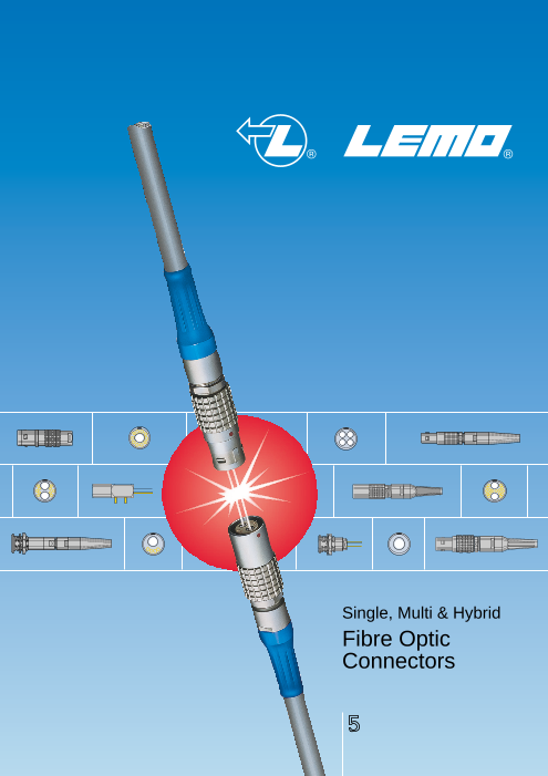
Single, Multi & Hybrid
Fibre Optic
Connectors
5
Dear Customers,
As far as data transmission is concerned, the superior characteristics of fibre optics compared to elec-
trical cables are clearly recognised today.
The advantages of fibre optics include a transmission capacity 10 times greater than that of conventional
coaxial cables, in only one tenth of the size. The reduced weight and space requirements make handling
and line installation much easier. Furthermore, fibre optics is characterized by low signal amplitude loss,
no susceptibility to electromagnetic interference, and an absence of interference between neighbouring
lines. It also offers greater security due to the difficulty of intercepting optical signals.
The growing number of applications is more and more varied, and the annual growth rate of fibre optics
is greater than 10%. Current applications of fibre optics include: telemetry, process control, data trans-
mission, cable and closed circuit television, as well as laser signal transmission in medical applications.
However, most systems equipped with fibre optics also require simultaneous electrical energy for control
operations and power supply. Current practice involves the use of separate electrical and fibre optic
connectors.
The new technology developed by LEMO greatly simplifies this practice by combining electrical and fibre
optic signals in a single connector.
LEMO can now offer you a full range of mixed electrical/fibre optic connectors for singlemode or multi-
mode transmission. This product range is available with metal or plastic outer shells, as well as in a wa-
tertight version.
The range is completed by the addition of a single channel fibre optic connector series. All LEMO fibre
optic connectors use a plug and socket push-pull self-latching connection system, obviating the need
for plug to plug adaptors. This is a major advantage of the LEMO technology over its competitors.
With the aim of providing the best possible answers to your fibre optic needs, LEMO has established an
important research and development facility to provide quick and effective solutions to your design re-
quirements.
LEMO ISO 9001 certified has been improving its “quality culture” with the aim of reaching TQM. Offering
zero defect products with due regard to the environment and meeting delivery requirements, are LEMO’s
two main concerns.
d Qie u al it y S LEMO SA
General Management
ISO 9001
Reg. No. 10472 - 03
No reproduction or use without express permission of editorial or pictorial content, in any manner. Printed in Switzerland, April 2002 © LEMO SA
LEMO reserve the right at all times to modify and improve specifications without any notification. Pdf updated, March 2011
Certif
ste
m
y
® ®
Table of Contents
General Production Programme .................................................................................................page 3
Main Characteristics and Types .............................................................................................................3
Series and Types ......................................................................................................................................4
LEMO’s Push-Pull Self-Latching Connection System ..........................................................................5
Fibre Optic Connectors Production Programme ..................................................................................6
Introduction ..............................................................................................................................................7
General Characteristics ...................... Selection of the LEMO Fibre Optic Contacts, Series and Contact Configurations.....................................8
Acceptable Cable Diameter .......................................................................................................................9
Selection of Electrical Contact Types.........................................................................................................9
Part Numbering System ...........................................................................................................................10
00 Series .................................................... Interconnections.......................................................................................................................................13
Model Description ....................................................................................................................................13
Part Section Showing Internal Components ................................................................................................14
Technical Characteristics ..........................................................................................................................14
Alignment Key and Polarized Keying Systems ........................................................................................14
Part Number Example..............................................................................................................................15
Models - Series ........................................................................................................................................16
Fibre Type ................................................................................................................................................17
Housing, Cable Fixing Type, Bend Relief, Tooling, Panel Cut-Outs ........................................................18
0B Series .................................................... Interconnections.......................................................................................................................................21
Model Description ....................................................................................................................................21
Part Section Showing Internal Components ................................................................................................22
Technical Characteristics ..........................................................................................................................22
Alignment Key and Polarized Keying Systems ........................................................................................22
Part Number Example..............................................................................................................................23
Models - Series ........................................................................................................................................24
Fibre Type, Housing.................................................................................................................................25
Bend Relief, Tooling, Panel Cut-Outs ......................................................................................................26
0K Series .................................................... Interconnections.......................................................................................................................................29
Model Description ....................................................................................................................................29
Part Section Showing Internal Components ................................................................................................30
Technical Characteristics ..........................................................................................................................30
Alignment Key and Polarized Keying Systems ........................................................................................30
Part Number Example..............................................................................................................................31
Models - Series ........................................................................................................................................32
Fibre Type ................................................................................................................................................32
Housing, Bend Relief, Tooling, Panel Cut-Outs .......................................................................................33
2B to 5B Series ....................................... Interconnections.......................................................................................................................................37
Model Description ....................................................................................................................................37
Part Section Showing Internal Components ................................................................................................38
Technical Characteristics ..........................................................................................................................38
Alignment Key and Polarized Keying Systems ........................................................................................38
Part Number Example..............................................................................................................................39
Models - Series ........................................................................................................................................40
Tooling, Panel Cut-Outs...........................................................................................................................45
2K to 5K Series ....................................... Interconnections.......................................................................................................................................47
Model Description ....................................................................................................................................47
Part Section Showing Internal Components ................................................................................................48
Technical Characteristics ..........................................................................................................................48
Alignment Key and Polarized Keying Systems ........................................................................................48
Part Number Example..............................................................................................................................49
Models - Series ........................................................................................................................................50
Tooling, Panel Cut-Outs...........................................................................................................................53
Types (2B-5B and 2K-5K series) ..........................................................................................................55
Housing, Electrical Contact (2B-5B and 2K-5K series).........................................................................58
Collets (2B-5B and 2K-5K series) .........................................................................................................59
Variant (2B-5B and 2K-5K series).........................................................................................................61
1
® ®
Table of Contents
3K.93C Series .......................................... Interconnections.......................................................................................................................................65
Model Description ....................................................................................................................................65
Part Section Showing Internal Components ................................................................................................66
Technical Characteristics ..........................................................................................................................66
Alignment Key and Polarized Keying Systems ........................................................................................67
Part Number Example..............................................................................................................................67
Models - Series ........................................................................................................................................68
Types .......................................................................................................................................................71
Fibre Optic Contact, Accessories.............................................................................................................72
Tooling .....................................................................................................................................................74
Fibre Optic Tooling, Crimping Tools for Electrical Contacts.....................................................................75
Termination Instruction, Panel Cut-Outs ..................................................................................................76
F1 Fibre Optic Contact ........................ Introduction, Part Section Showing Internal Components........................................................................77
Technical Characteristics, Part Number Example....................................................................................77
Model - FO Contact Type, Fibre Type......................................................................................................78
F2 Fibre Optic Contact ........................ Introduction, Part Section Showing Internal Components, Technical Characteristics .............................79
Part Number Example, Model - FO Contact Type, Fibre Type ................................................................80
Cable Fixing Type, Accessory..................................................................................................................81
Insertion and Extraction of the Fibre Optic Contacts................................................................................82
Accessories .............................................. Insulators, Crimp Electrical Contacts .......................................................................................................85
Caps.........................................................................................................................................................86
Bend Reliefs .............................................................................................................................................91
Insulating Washers, Double Panel Washers............................................................................................93
Locking Washers, Tapered Washers, Hexagonal Nuts ...........................................................................94
Notched Nuts, Conical Nuts, Round Nuts ................................................................................................95
Earthing Washers.....................................................................................................................................96
Tooling ........................................................ Spanners..................................................................................................................................................97
Pliers, Taps ..............................................................................................................................................99
Crimping Tools for Electrical Contacts, Positioners, Turrets ..................................................................100
Extraction Tools, Retention Testing Tools .............................................................................................101
Tools for type C Coaxial Contacts Crimping Tool, Dies, Extractors..............................................................................................................102
Fibre Optic Tooling ............................... Complete Workstation............................................................................................................................103
Crimping Tool, Epoxy Curing Jig, Epoxy Curing Oven, Polishing Tool ..................................................104
Fibre Inspection Microscope, Microscope Adaptor, Extractor ................................................................105
F2 Contact Alignment Device, F4 Contact Alignment Device ................................................................105
Cleaning Tool, Cleaning Kit....................................................................................................................106
Technical Characteristics .................. Outer shell ..............................................................................................................................................107
Insulator .................................................................................................................................................108
Fibre Optic Contacts ..............................................................................................................................109
Electrical Contact ...................................................................................................................................112
Cable Fixing ...........................................................................................................................................115
Preferred Fibre Optic Cable Types ........................................................................................................118
2
Page5
General Production Program、Main Characteristics and Types
® ®
General Production Program
Connectors Unipole from 2 to 150 Amps Patch Panels For video HDTV applications: 3 coax 75 Ω + 2LV
Coaxial 50 and 75 Ω For fibre optic applications
Coaxial 50 Ω (NIM-CAMAC)
Coaxial 50 Ω for frequency → 12 GHz Adaptors For BNC, C, UHF, N, CINCH, GEN-RADIO connectors
Multicoaxial 50 and 75 Ω For TNC, SMA connectors
Multipole from 2 to 106 contacts
High Voltage 3, 5, 8, 10, 15, 30 and 50 kV cc Accessories ● Insulator for crimp contacts
Multi High Voltage 3, 5, and 10 kV cc ● Crimp contacts
Triaxial 50 and 75 Ω Coaxial contacts
Quadrax Triaxial contacts
Mixed: High Voltage (LV) + Low Voltage (LV) ● Fibre optic contacts
Mixed: Coax + LV ● Fibre optic ferrules
Mixed: Triax + LV ● Caps and bend reliefs
Thermocouple ● Insulating washers
Multithermocouple ● Double plastic panel washers
● Fibre optic single-mode ● Locking washers
● Fibre optic multi-mode ● Tapered washers
● Mixed: fibre optic + LV ● Hexagonal nuts
Mixed: fibre optic + coax + LV ● Conical nuts
Fluidic ● Round nuts
Multifluidic ● Notched nuts
Mixed: fluidic + LV ● Earthing washers
Subminiature Lead-through with cable collet
Miniature
Printed circuit board Tooling ● Spanners
Remote handling ● Spanners for assembling plug
Watertight ● Assembly tool
Sealed (pressure and/or vacuum) ● Pliers
● With plastic outer shell ● Tap
● With aluminium outer shell ● Crimping tools
● With stainless steel outer shell ● Positioners
With special radiation resistant insulator material ● Crimping dies
With screw thread coupling for very high pressure ● Extractors
With microswitch ● Insertion testing tool for crimp contacts
● Fibre optic termination workstation
● Fibre optic polishing tools
Patch Panels For audio-mono applications: triax
For audio-mono applications: 3 contacts On request Filtered connectors
For audio-stereo applications: quadrax ● Connectors with special alloy housing
For audio-stereo applications: 6 contacts Mixed special connectors
For video applications: coax 75 Ω ● Assembly onto cable
● Connectors, accessories and tools found in this catalogue.
Main Characteristics and Types
Series STANDARD WATERTIGHT KEYED KEYEDWATERTIGHT SCREW
01 (Minax) 0E to 6E 00 (multipole) 0K to 5K 03
00 (NIM-CAMAC) 3T 0B to 5B 0F to 5F 0V to 5V
00 (unipole) 4M 2G/5G 2N to 5N 0W to 5W
05 / R0 2U to 5U
0S to 6S
0A / 4A
1D / 2C
1Y-3Y-6Y
Latching Push-Pull Screw
Key Stepped insulator (Half-Moon) Key (G) or other key-way code Key (G) or stepped insulator (Half-Moon)
Shell Metal or plastic Metal Metal or plastic Metal Metal
Insulator Hermaphroditic or cylindrical Cylindrical Hermaphroditic or cylindrical
Contact Solder or print Solder, crimp or print Solder(crimp or print)
3
® ®
Series and Types
Types
Series
01 ●
00 ● ● ● ●
05 ●
R0 ●
0A ● ●
0S ● ● ● ● ● ●
1S ● ● ● ● ● ● ●
Standard 2S ● ● ● ● ● ● ● ● ●
3S ● ● ● ● ● ● ● ● ● ●
4S ● ● ● ● ● ● ● ● ● ● ●
5S ● ● ● ● ● ● ● ●
6S ● ● ●
1D ●
2C ● ●
4A ●
1Y-3Y-6Y ●
0E ● ● ● ● ● ●
1E ● ● ● ● ● ● ●
2E ● ● ● ● ● ● ● ● ●
3E ● ● ● ● ● ● ● ● ● ●
Watertight 4E ● ● ● ● ● ● ● ●
5E ● ● ● ● ● ●
6E ● ● ●
3T ● ●
4M ● ●
00 ● ●
0B ● ● ● ●
1B ● ● ●
2B ● ● ● ● ● ● ● ● ●
Keyed 3B ● ● ● ● ● ● ● ● ●
4B ● ● ● ● ● ● ● ● ● ●
5B ● ● ● ● ● ● ● ●
2G ●
5G ●
0K ● ● ● ●
1K ● ● ●
2K ● ● ● ● ● ● ● ●
Keyed 3K ● ● ● ● ● ● ● ● ● ●
watertight 4K ● ● ● ● ● ● ● ● ● ●
5K ● ● ● ● ● ● ● ●
0F to 5F ●
2N to 5N ● ● ● ● ● ● ● ●
03 ● ●
0V ● ● ● ● ●
1V ● ● ● ● ● ●
2V ● ● ● ● ● ● ● ●
Screw 3V ● ● ● ● ● ● ● ● ●
4V ● ● ● ● ● ● ● ●
5V ● ● ● ● ● ●
0W to 5W ● ● ● ● ● ● ● ● ●
2U to 5U ● ● ● ●
Note: ● = included in this catalogue, ● = available but not included in this catalogue.
4
Unipole
Coaxial 50 Ω
Coaxial 75 Ω
Multipole
High Voltage
Triaxial 50 Ω
Triaxial 75 Ω
Quadrax
Multi HV
Multi Coaxial
Mixed HV+LV
Mixed Coax+LV
Mixed Triax+LV
Fibre Optic
Multi FO
Mixed FO+LV+…
Fluidic
Multi fluidic
Mixed fluidic+LV
Thermocouple
Page7
LEMO's Push-Pull Self-Latching Connection System
® ®
LEMO’s Push-Pull Self-Latching Connection System
This self-latching system is renowned worldwide for its easy and quick mating and unmating features. It provides absolute
security against vibration, shock or pull on the cable, and facilitates operation in a very limited space.
The LEMO Push-Pull self-latching system allows
the connector to be mated by simply pushing
the plug axially into socket.
Once firmly latched, connection cannot be broken
by pulling on the cable or any other component
part other than the outer release sleeve.
When required, the connector is disengaged
by a single axial pull on the outer release sleeve.
This first disengages the latches and then withdraws
the plug from the socket.
Mechanical latching characteristics
00, B series K watertight series
Force Series Force Series
Fv (N) 00 0B 2B 3B 4B 5B (N) 0K 2K 3K 4K 5K
Fv 9 10 15 17 39 48 Fv 14 20 32 65 85
Fd 7 8 12 14 38 38 Fd 9 13 25 40 60
Fa 120 250 300 550 700 800 Fa 250 400 550 700 800
Notes: Forces were measured on outer shells not fitted with contacts .
Fd Fv: average latching force
Fd: average unmating force
with axial pull on the outer shell
Fa: average pull force
with axial pull on the collet nut
Fa
5
Page8
Fibre Optic Connectors Production Program
® ®
Fibre Optic Connectors Production Program
The production program is divided into 12 series of connectors. Their main characteristics and applications are shown below.
Series 00 0B 0K 2B to 5B 2K to 5K 3K.93C
Latching Push-Pull With «W»key-way
Shell Metal Metal or plastic Metal
Miniature Watertight Watertight Watertight Feature to IP68 to IP68 to IP68
Cable Single fibre Multi fibre or Mixed optical/electrical Mixed HDTV
Construction optical/electrical
Contact Type F4 F3 F2 F1 F2 F2
Single-mode Single-mode Single-mode Single-mode
Fibre Type or or or orMulti-mode Multi-mode Multi-mode Multi-mode Multi-mode Multi-modefibres ≤ 100/140µm fibres ≥ 100/140µm fibres ≤ 100/140µm fibres ≥ 100/140µm fibres ≤ 100/140µm fibres ≤ 100/140µm
Mean insertion 0.10 dB (s/m) 0.10 dB (s/m) 0.10 dB (s/m) 0.10 dB (s/m)
loss 0.25 dB (m/m) 1.13 dB 1.13 dB0.25 dB (m/m) 0.25 dB (m/m) 0.25 dB (m/m)
Ferrule Material Ceramic Ceramic or metal Ceramic Ceramic or metal Ceramic Ceramic
Spherical Spherical, Spherical Spherical, Spherical Spherical
with physical non-contact with with physical non-contact with with physical with physical
Interface Type contact controlled gap contact controlled gap contact contact
of the fibre of the fibre of the fibre of the fibre of the fibre of the fibre
end face (PC) end face end face (PC) end face end face (PC) end face (PC)
Page 11 to 18 19 to 26 27 to 34 35 to 46 47 to 54 63 to 76
6
Page9
Introduction、Propagation of Light and Fibre Type
® ®
Introduction
This catalog gives the complete description of LEMO The 2B to 5B Series
fibre optic connectors. Our manufacturing program
has been extended to 12 series with specific mating and These connectors series range from 2B to 5B, and have
environmental characteristics. been designed to work with LEMO F1 or F2 type fibre
optic contacts. They are suitable for use with multi fibre or
Each series includes a wide variety of plugs, sockets mixed fibre optical/electrical cables fitted with single-
or housings for electro-optic devices available in a mode or multi-mode fibres up to 1500 micron in diameter.
large choice of combinations of fibre optic and electrical The connectors offer a variety of features:
contacts within the same housing. – alignment key preventing all errors in alignment;
Shells are adapted to all round cables to a maximum dia- – polarized keying system, the various keying alterna-
meter of 25 mm. tives prevent unwanted cross mating of otherwise
similar connectors;
LEMO connectors feature ceramic or metal ferrules – higher contact density; and
for the fibre optic contacts to provide alignment for both – possible use of crimp contacts to reduce cable assem-
single-mode and multi-mode fibres. bly time.
They are manufactured to the highest precision in order
to ensure optimum optical performances even in the most The 2K to 5K Series
severe applications.
This product family includes the 2K to 5K series, and are
Numerous accessories as well as a complete range of watertight (IEC 60529/IP 66-IP 68) available in the same
tools for fibre optic termination, are available. types as the 2B to 5B series. The connectors are ideal for
use in harsh environments.
The 00 Series
The video HDTV 3K.93C Series
The characteristic feature of this connector series
is the small size requiring minimum mounting space This new range of high performance fibre optic camera
requirement. connectors has been developed to meet the needs of the
Connectors are suitable for use with single fibre cables new generation of digital TV cameras. Contact configura-
fitted with single-mode or multi-mode fibres. tion includes 2 fibre optic contacts for single-mode fibres,
2 electrical contacts for power and 2 electrical contacts
The 0B Series for signal. This series conforms to the Japanese ARIB
technical report BTA S-1005B, to the ANSI/SMPTE 304
A simple and proven construction with ceramic or metallic M-1998 and 311M-1998 standards and to the European
ferrules in a fibre optic contact primarily intended for use EBU Technical Recommendation R100-1999.
with large size multi-mode fibres ranging from 140 to Connectors are qualified for use in UL approved equip-
1500 micron external diameters. ment such as those specified in UL 1419 «Professional
Video and Audio Equipment»
The 0K Series
CE marking
This series is watertight (IEC 60529/IP 66-IP 68) and is
ideal for use in harsh environments. CE marking means that the appliance or equipment
It uses the standard LEMO F2 fibre optic contact which bearing it complies with the protection requirements of
has undergone extensive mechanical, optical and envi- one or several European safety directives.
ronmental testing. CE marking applies to complete products or
Connectors are suitable for use with single fibre cables equipment, but not to optical/electromechanical com-
fitted with single-mode or multi-mode fibres. ponents, such as connectors.
Propagation of Light and Fibre Type
The diagrams show the typical transmission characte-
ristic of single-mode and multi-mode fibres. Cross section Propagation Received
In multi-mode fibres, the effect of modal dispersion in the fibre pulse
causes a spread in the received pulse and therefore Fig. 1
limits the bandwidth of the transmission system (Fig. 1). Multi-mode fibre
Typical step index Core Cladding
AE AA
If the fibre core is < 10 µm and the wavelength is ≥ 1300
nm, then only the fundamental mode is transmitted in the
single-mode fibre (Fig. 2). 200 µm n
t t
The dispersion effects of single-mode fibres are very
small and consequently they offer higher bandwidths Fig. 2
when compared with multi-mode fibres. However, multi- Single-mode fibre Core Cladding
mode fibres are usually ideal for short distance applica- AE AE
tions because they require less input optical power and
can be driven by simple low cost LEDs. ≈10 µm n
t t
7
125 µm 380 µm
Refractive
index profile
Transmitted
pulse
Page10
General Characteristics、Selection of the LEMO Fibre Optic Contacts、Series and contact configurations
® ®
General Characteristics
Selection of the LEMO Fibre Optic Contacts
In order to ensure the highest technical performance and to provide the optimum solution for a diversity of applications,
LEMO has developed four types of fibre optic contacts; designated F1, F2, F3, and F4. These contacts are designed to
operate with single fibre, multi fibre, and mixed fibre optical/electrical cable constructions and cater to single and multi-
mode fibres from 9/125 to 1500 µm diameter.
The choice of fibre optic contacts depends upon the following criteria:
– Cable construction (single fibre, multi fibre, mixed optical/electrical)
– Fibre type (single-mode or multi-mode).
The table below shows the suitability of each contact type with different fibres and cables.
Note that the multi fibre cable can contain many types of optic fibres or a group of fibres and electrical cables leading to
mixed optical/electrical connectors.
Cable Structure Fibre Types and dimensions
multi-mode
single fibre multi fibre or mixed single-mode ≤ 100/140µm ≥ 100/140µm
F1
F2
F3
F4
Series and contact configurations
Single and Multi F.O. Mixed F.O. + L.V.
Series Series
Number Number
of F.O. of F.O. Number of L.V.
contacts contacts electrical contacts
1 ● ● ● 1 2, 4, 6 or 10 ●
2 ● 1 22 ●
4 ● 2 4, 6, 10 or 16 ●
10 ● 2 6, 7, 12, 16 or 18 ●
14 ● 3 6 or 12 ●
3 10 ●
Note: ● = available contact configuration
4 5 or 9 ●
9 3 ●
Mixed F.O. + L.V. + H.V. Mixed F.O. + L.V. + Coax
Series Series
Number Number Number Number Number
of F.O. of L.V. of H.V.
Number of L.V. of coax
contacts electrical electrical
of F.O.
contacts electrical electricalcontacts contacts contacts contacts
2 2 2 ● 1 6 1 ●
6 2 4 ● 1 16 1 ●
12 1 2 ● 2 – 2 ●
2 6 1 ●
8
00
0B
0K
2B-2K
3B-3K
00 Contact type
4B-4K
0B
5B-5K
0K
3K.93C
2B-2K
3B-3K
4B-4K
5B-5K
3K.93C
00 00
0B 0B
0K 0K
2B-2K 2B-2K
3B-3K 3B-3K
4B-4K 4B-4K
5B-5K 5B-5K
3K.93C 3K.93C
Page11
Acceptable cable diameter、Selection of electrical contact types
® ®
Acceptable cable diameter
Series
Cable ø
(mm)
min 0.25 2.5 2.5 1.5 4.1 5.1 9.6 8.3 3.6 3.6 3.6 3.6
max 3.00 4.4 3.0 9.7 11.7 16.0 25.0 16.5 6.5 9.0 13.5 23.5
Selection of electrical contact types
Solder contacts
The conductor bucket of these contacts is machined at an angle to form a cup into which the solder can flow.
Contact Conductor
Solid Stranded
ø A ø C
ø A ø C (mm) (mm) AWG Section AWG Section
max. max (mm2) max. max (mm2)
0.7 0.80 22 0.34 221) 0.34
0.9 0.80 22 0.34 221) 0.34
ø A ø C 1.3 1.00 20 0.50 201) 0.50
2.0 1.80 14 1.50 16 1.50
4.0 3.70 10 6.00 10 6.00
Note: 1) For a given AWG, the diameter of some stranded conductor
designs is larger than the solder cup diameter. Make sure that the
maximum conductor diameter is smaller than ø C.
Crimp contacts
The crimp contacts are designed to be crimped with the standard four-indent method according to MIL-C-22520F,
class 1, type 1.
Contact Conductor stranded
F
ø A ø C ø A ø C AWG stranded Section (mm2)
r
(N)
(mm) (mm) min. max. min. max.
0.7 0.80 26 221) 0.140 0.34 22
0.9 1.10 24 20 0.250 0.50 30
ø A ø C 1.40 20 18 0.500 1.00
1.3 40
1.90 2) 18 14 1.000 1.50
1.6 1.90 18 141) 1.000 1.50 50
2.0 2.40 16 121) 1.500 2.50 65
Note: Note: Fr = mean contact retention force in the insulator (according to
1) For a given AWG, the diameter of some stranded conductor designs IEC 60512-8 test 15a).
is larger than the solder cup diameter. Make sure that the maximum Crimp contacts can also be supplied with a reduced crimp barrel.
conductor diameter is smaller than ø C. Please consult factory or our Unipole/Multipole catalog.
2) These contacts are special with an oversized crimp bucket and can
be used only with the series 3K.93C.
A detailed range of conductor dimensions that can be crimped into LEMO contacts is given in the table above. See also
the section on tooling (pages 97 to 106).
Coaxial contacts
The type C coaxial contact is removable and fixed in place by clips. Cable attachement is made by crimping. The square
form is used to captivate center conductor and hexagonal crimping method for the cable shield.
A detailed range of coaxial cable that can be installed into our type C coaxial contact is given in the table below.
Group Type
1 RG.174A/U, RG.188A/U, RG.316/U
2 RG.178B/U, RG.196A/U
3 RG.179B/U, RG.187A/U
9
00
0B
0K
2B
3B
4B
5B
3K.93C
2K
3K
4K
5K
Page12
Part Numbering System
® ®
@@@@@@@@e?@@@@@@@@e?@@@@@@@@?e@@@@@@@@e?@@@@@@@@?e@@@@@@@@e?@@@@@@@@?e@@@@@@@@e?@@@@@@@@?e@@@@@@@@e?@@@@@@@@?e@@@@@@@@e?@@@@@@@@
@@@@@@@@e?@@@@@@@@e?@@@@@@@@?e@@@@@@@@e?@@@@@@@@?e@@@@@@@@e?@@@@@@@@?e@@@@@@@@e?@@@@@@@@?e@@@@@@@@e?@@@@@@@@?e@@@@@@@@e?@@@@@@@@
@@h? @@
@@ ? @@
@@ ? @@
@@h? @@
@@ ? @@
@@ ? @@
@@ @@
@@ @@
Part Numbering System @@ @@@@ @@@@ @@@@ @@@@ @@@@ @@@@ @@@@ @@@@ @@@@ @@@@ @@@@ @@@@ @@@@ @@@@ @@@@ @@@@ @@@@ @@@@ @@@@ @@@@ @@@@ @@@@ @@@@ @@@@ @@@@ @@@@ @@@@ @@@@ @@@@ @@@@ @@@@ @@@@ @@@@ @@@@ @@@@ @@@@ @@@@ @@@@ @@@@ @@@@ @@@@ @@@@ @@@@ @@@@ @@
@@ @@
● ● ● ● ● ● ● ● ● ● ● ● ● ● @@ @@@@ @@@@ @@@@ @@@@ @@@@ @@@@ @@@@ @@@@ @@@@ @@@@ @@@@ @@@@ @@@@ @@@@ @@@@ @@@@ @@@@ @@@@ @@@@ @@@@ @@@@ @@@@ @@@@ @@
@@ @@
@@ @@
@@ @@
@@ @@
@@ @@
@@ @@
@@ @@
@@ @@
@@ @@
@@ @@
@@ @@
@@ @@
@@ @@
@@ @@
@@ @@
@@ @@
@@ @@
@@ @@
@@ @@
@@ @@
@@ @@
@@ @@
@@ @@
@@ @@
@@ @@
@@ @@
@@ @@
@@ @@
@@ @@
@@ @@
@@ @@
@@ @@
@@g ?@@
@@ ?@@
@@ ?@@
@@g ?@@
@@ ?@@
@@ ?@@
@@@@@@@@ ?@@@@@@@@?e@@@@@@@@e?@@@@@@@@?e@@@@@@@@e?@@@@@@@@?e@@@@@@@@e?@@@@@@@@?e@@@@@@@@e?@@@@@@@@?e@@@@@@@@e?@@@@@@@@ ?@@@@@@@@
@@@@@@@@ ?@@@@@@@@?e@@@@@@@@e?@@@@@@@@?e@@@@@@@@e?@@@@@@@@?e@@@@@@@@e?@@@@@@@@?e@@@@@@@@e?@@@@@@@@?e@@@@@@@@e?@@@@@@@@ ?@@@@@@@@
@@@@@@@@e?@@@@@@@@e?@@@@@@@@?e@@@@@@@@e?@@@@@@@@?e@@@@@@@@e?@@@@@@@@?e@@@@@@@@e?@@@@@@@@?e@@@@@@@@e?@@@@@@@@?e@@@@@@@@e?@@@@@@@@
@@@@@@@@e?@@@@@@@@e?@@@@@@@@?e@@@@@@@@e?@@@@@@@@?e@@@@@@@@e?@@@@@@@@?e@@@@@@@@e?@@@@@@@@?e@@@@@@@@e?@@@@@@@@?e@@@@@@@@e?@@@@@@@@
@@h? @@
@@ ? @@
@@ ? @@
@@h? @@
@@ ? @@
@@ ? @@
@@ @@
Series @@ @@Connectors series and size should be selected @@ @@@@ @@@@ @@@@ @@@@ @@@@ @@@@ @@@@ @@@@ @@@@ @@@@ @@@@ @@@@ @@@@ @@@@ @@@@ @@@@ @@@@ @@@@ @@@@ @@@@ @@@@ @@@@ @@@@ @@@@ @@@@ @@@@ @@@@ @@@@ @@@@ @@@@ @@@@ @@@@ @@@@ @@@@ @@@@ @@
@@ @@
@@ @@
@@ @@
@@ @@
@@ @@
@@ @@
@@ @@
@@ @@
@@ @@
@@ @@
● ● @@ @@@@ @@@@ @@@@ @@@@ @@@@ @@@@ @@@@ @@@@ @@@@ @@@@ @@@@ @@@@ @@@@ @@@@ @@@@ @@@@ @@@@ @@@@ @@@@ @@according to the type of fibre, single-mode or @@ @@@@ @@@@ @@@@ @@@@ @@@@ @@@@ @@@@ @@@@ @@@@ @@@@ @@@@ @@@@ @@@@ @@@@ @@@@ @@@@ @@@@ @@@@ @@@@ @@@@ @@@@ @@@@ @@@@ @@@@ @@@@ @@@@ @@@@ @@@@ @@@@ @@@@ @@@@ @@@@ @@@@ @@@@ @@@@ @@
@@g ?@@
@@ ?@@
@@ ?@@
@@g ?@@
@@ ?@@
@@ ?@@
@@@@@@@@ ?@@@@@@@@?e@@@@@@@@e?@@@@@@@@?e@@@@@@@@e?@@@@@@@@?e@@@@@@@@e?@@@@@@@@?e@@@@@@@@e?@@@@@@@@?e@@@@@@@@e?@@@@@@@@ ?@@@@@@@@
@@@@@@@@ ?@@@@@@@@?e@@@@@@@@e?@@@@@@@@?e@@@@@@@@e?@@@@@@@@?e@@@@@@@@e?@@@@@@@@?e@@@@@@@@e?@@@@@@@@?e@@@@@@@@e?@@@@@@@@ ?@@@@@@@@
multi-mode, cable structure and dimensions.
See table on p. 6 (fibre optic connectors production pro- 0 0 00 series Single fibre
gram) and p. 8 (selection of the LEMO fibre optic contacts).
Selection should also consider the environ- 3 K 3K series Multi fibre or mixed
mental requirements such as indoor or outdoor
applications etc…
See again table on p. 6 (fibre optic connector production
program).
@@@@@@@@e?@@@@@@@@e?@@@@@@@@?e@@@@@@@@e?@@@@@@@@?e@@@@@@@@e?@@@@@@@@?e@@@@@@@@e?@@@@@@@@?e@@@@@@@@e?@@@@@@@@?e@@@@@@@@e?@@@@@@@@
@@@@@@@@e?@@@@@@@@e?@@@@@@@@?e@@@@@@@@e?@@@@@@@@?e@@@@@@@@e?@@@@@@@@?e@@@@@@@@e?@@@@@@@@?e@@@@@@@@e?@@@@@@@@?e@@@@@@@@e?@@@@@@@@
@@h? @@
@@ ? @@
@@ ? @@
@@h? @@
@@ ? @@
@@ ? @@
Type @@ @@Contact arrangements (type) within a given @@ @@@@ @@@@ @@@@ @@@@ @@@@ @@@@ @@@@ @@@@ @@@@ @@@@ @@@@ @@@@ @@@@ @@@@ @@@@ @@@@ @@@@ @@@@ @@@@ @@@@ @@@@ @@@@ @@@@ @@@@ @@@@ @@@@ @@@@ @@@@ @@@@ @@@@ @@@@ @@@@ @@@@ @@@@ @@@@ @@@@ @@
@@ @@
@@ @@
@@ @@
@@ @@
@@ @@
@@ @@
@@ @@
@@ @@
@@ @@
@@ @@
● ● ● @@ @@@@ @@@@ @@@@ @@@@ @@@@ @@@@ @@@@ @@@@ @@@@ @@@@ @@@@ @@@@ @@@@ @@@@ @@@@ @@@@ @@@@ @@@@ @@@@series can be defined according to the fibre size @@@@ @@@@ @@@@ @@@@ @@@@ @@@@ @@@@ @@@@ @@@@ @@@@ @@@@ @@@@ @@@@ @@@@ @@@@ @@@@ @@@@ @@@@ @@@@ @@@@ @@@@ @@@@ @@@@ @@@@ @@@@ @@@@ @@@@ @@@@ @@@@ @@@@ @@@@ @@@@ @@@@ @@@@ @@@@ @@@@ @@
@@g ?@@
@@ ?@@
@@ ?@@
@@g ?@@
@@ ?@@
@@ ?@@
@@@@@@@@ ?@@@@@@@@?e@@@@@@@@e?@@@@@@@@?e@@@@@@@@e?@@@@@@@@?e@@@@@@@@e?@@@@@@@@?e@@@@@@@@e?@@@@@@@@?e@@@@@@@@e?@@@@@@@@ ?@@@@@@@@
@@@@@@@@ ?@@@@@@@@?e@@@@@@@@e?@@@@@@@@?e@@@@@@@@e?@@@@@@@@?e@@@@@@@@e?@@@@@@@@?e@@@@@@@@e?@@@@@@@@?e@@@@@@@@e?@@@@@@@@ ?@@@@@@@@
for single fibre connector or cable design for
multi fibre or mixed. B A 4 Single fibre
See table on p. 8 (series and contact configuration) and
type table in each series. 0 3 A Multi fibre or mixed
@@@@@@@@e?@@@@@@@@e?@@@@@@@@?e@@@@@@@@e?@@@@@@@@?e@@@@@@@@e?@@@@@@@@?e@@@@@@@@e?@@@@@@@@?e@@@@@@@@e?@@@@@@@@?e@@@@@@@@e?@@@@@@@@
@@@@@@@@e?@@@@@@@@e?@@@@@@@@?e@@@@@@@@e?@@@@@@@@?e@@@@@@@@e?@@@@@@@@?e@@@@@@@@e?@@@@@@@@?e@@@@@@@@e?@@@@@@@@?e@@@@@@@@e?@@@@@@@@
@@h? @@
@@ ? @@
@@ ? @@
@@h? @@
@@ ? @@
@@ ? @@
@@ @@
Model @@ @@Models within a given series can be selected @@ @@@@ @@@@ @@@@ @@@@ @@@@ @@@@ @@@@ @@@@ @@@@ @@@@ @@@@ @@@@ @@@@ @@@@ @@@@ @@@@ @@@@ @@@@ @@@@ @@@@ @@@@ @@@@ @@@@ @@@@ @@@@ @@@@ @@@@ @@@@ @@@@ @@@@ @@@@ @@@@ @@@@ @@@@ @@@@ @@
@@ @@
@@ @@
@@ @@
@@ @@
@@ @@
@@ @@
@@ @@
@@ @@
@@ @@
@@ @@
@@ @@
@@ @@
@@ @@
@@ @@
@@ @@
@@ @@
@@ @@
@@ @@
@@ @@
@@ @@
@@ @@
@@ @@
@@ @@
@@ @@
@@ @@
@@ @@
@@ @@
@@ @@
@@ @@
@@ @@
according to the application and the panel ● ● ● @@ @@@@ @@@@ @@@@ @@@@ @@@@ @@@@ @@@@ @@@@ @@@@ @@@@ @@@@ @@@@ @@@@ @@@@ @@@@ @@@@ @@@@ @@@@ @@@@ @@@@ @@@@ @@@@ @@@@ @@@@ @@@@ @@@@ @@@@ @@@@ @@@@ @@@@ @@@@ @@@@ @@@@ @@@@ @@@@ @@
@@g ?@@
@@ ?@@
@@ ?@@
@@g ?@@
@@ ?@@
@@ ?@@
@@@@@@@@ ?@@@@@@@@?e@@@@@@@@e?@@@@@@@@?e@@@@@@@@e?@@@@@@@@?e@@@@@@@@e?@@@@@@@@?e@@@@@@@@e?@@@@@@@@?e@@@@@@@@e?@@@@@@@@ ?@@@@@@@@
@@@@@@@@ ?@@@@@@@@?e@@@@@@@@e?@@@@@@@@?e@@@@@@@@e?@@@@@@@@?e@@@@@@@@e?@@@@@@@@?e@@@@@@@@e?@@@@@@@@?e@@@@@@@@e?@@@@@@@@ ?@@@@@@@@
mounting conditions.
F ● ● Plug
See models available in each series.
When available make the right key-way selection. E ● ● Socket
@@@@@@@@e?@@@@@@@@e?@@@@@@@@?e@@@@@@@@e?@@@@@@@@?e@@@@@@@@e?@@@@@@@@?e@@@@@@@@e?@@@@@@@@?e@@@@@@@@e?@@@@@@@@?e@@@@@@@@e?@@@@@@@@
@@@@@@@@e?@@@@@@@@e?@@@@@@@@?e@@@@@@@@e?@@@@@@@@?e@@@@@@@@e?@@@@@@@@?e@@@@@@@@e?@@@@@@@@?e@@@@@@@@e?@@@@@@@@?e@@@@@@@@e?@@@@@@@@
@@h? @@
@@ ? @@
@@ ? @@
@@h? @@
@@ ? @@
@@ ? @@
Housing @@ @@@@ @@The housing material and surface finish depends @@ @@@@ @@@@ @@@@ @@@@ @@@@ @@@@ @@@@ @@@@ @@@@ @@@@ @@@@ @@@@ @@@@ @@@@ @@@@ @@@@ @@@@ @@@@ @@@@ @@@@ @@@@ @@@@ @@@@ @@@@ @@@@ @@@@ @@@@ @@@@ @@@@ @@@@ @@@@ @@@@ @@@@ @@@@ @@@@ @@
@@ @@
@@ @@
@@ @@
@@ @@
@@ @@
@@ @@
@@ @@
@@ @@
@@ @@
@@ @@
● @@ @@@@ @@@@ @@@@ @@@@ @@@@ @@@@ @@@@ @@@@ @@@@ @@@@ @@@@ @@@@ @@@@ @@@@ @@@@ @@@@ @@@@ @@@@material @@@@ @@on the environmental requirements. @@ @@@@ @@@@ @@@@ @@@@ @@@@ @@@@ @@@@ @@@@ @@@@ @@@@ @@@@ @@@@ @@@@ @@@@ @@@@ @@@@ @@@@ @@@@ @@@@ @@@@ @@@@ @@@@ @@@@ @@@@ @@@@ @@@@ @@@@ @@@@ @@@@ @@@@ @@@@ @@@@ @@@@ @@@@ @@@@ @@
@@g ?@@
@@ ?@@
@@ ?@@
@@g ?@@
@@ ?@@
@@ ?@@
@@@@@@@@ ?@@@@@@@@?e@@@@@@@@e?@@@@@@@@?e@@@@@@@@e?@@@@@@@@?e@@@@@@@@e?@@@@@@@@?e@@@@@@@@e?@@@@@@@@?e@@@@@@@@e?@@@@@@@@ ?@@@@@@@@
@@@@@@@@ ?@@@@@@@@?e@@@@@@@@e?@@@@@@@@?e@@@@@@@@e?@@@@@@@@?e@@@@@@@@e?@@@@@@@@?e@@@@@@@@e?@@@@@@@@?e@@@@@@@@e?@@@@@@@@ ?@@@@@@@@
See material available in each series. C Chrome-plated brass
@@@@@@@@e?@@@@@@@@e?@@@@@@@@?e@@@@@@@@e?@@@@@@@@?e@@@@@@@@e?@@@@@@@@?e@@@@@@@@e?@@@@@@@@?e@@@@@@@@e?@@@@@@@@?e@@@@@@@@e?@@@@@@@@
@@@@@@@@e?@@@@@@@@e?@@@@@@@@?e@@@@@@@@e?@@@@@@@@?e@@@@@@@@e?@@@@@@@@?e@@@@@@@@e?@@@@@@@@?e@@@@@@@@e?@@@@@@@@?e@@@@@@@@e?@@@@@@@@
@@h? @@
@@ ? @@
@@ ? @@
@@h? @@
@@ ? @@
@@ ? @@
Ferrule or @@ @@The ferrule material should be selected @@ @@@@ @@@@ @@@@ @@@@ @@@@ @@@@ @@@@ @@@@ @@@@ @@@@ @@@@ @@@@ @@@@ @@@@ @@@@ @@@@ @@@@ @@@@ @@@@ @@@@ @@@@ @@@@ @@@@ @@@@ @@@@ @@@@ @@@@ @@@@ @@@@ @@@@ @@@@ @@@@ @@@@ @@@@ @@@@ @@
@@ @@
@@ @@
@@ @@
@@ @@
@@ @@
@@ @@
@@ @@
@@ @@
@@ @@
@@ @@
@@ @@
● @@ @@@@ @@@@ @@@@ @@@@ @@@@ @@@@ @@@@ @@@@ @@@@ @@@@ @@@@ @@@@ @@@@ @@@@ @@@@ @@@@ @@@@ @@insulator @@ @@according to the availability in each series. @@ @@@@ @@@@ @@@@ @@@@ @@@@ @@@@ @@@@ @@@@ @@@@ @@@@ @@@@ @@@@ @@@@ @@@@ @@@@ @@@@ @@@@ @@@@ @@@@ @@@@ @@@@ @@@@ @@@@ @@@@ @@@@ @@@@ @@@@ @@@@ @@@@ @@@@ @@@@ @@@@ @@@@ @@@@ @@@@ @@@@ @@
@@g ?@@
@@ ?@@
@@ ?@@
@@g ?@@
@@ ?@@
@@ ?@@
@@@@@@@@ ?@@@@@@@@?e@@@@@@@@e?@@@@@@@@?e@@@@@@@@e?@@@@@@@@?e@@@@@@@@e?@@@@@@@@?e@@@@@@@@e?@@@@@@@@?e@@@@@@@@e?@@@@@@@@ ?@@@@@@@@
@@@@@@@@ ?@@@@@@@@?e@@@@@@@@e?@@@@@@@@?e@@@@@@@@e?@@@@@@@@?e@@@@@@@@e?@@@@@@@@?e@@@@@@@@e?@@@@@@@@?e@@@@@@@@e?@@@@@@@@ ?@@@@@@@@
material
For multi fibre or mixed connector the insulator Ceramic ferrule C Single fibre
material is PEEK
PEEK L Multi fibre or mixed
@@@@@@@@e?@@@@@@@@e?@@@@@@@@?e@@@@@@@@e?@@@@@@@@?e@@@@@@@@e?@@@@@@@@?e@@@@@@@@e?@@@@@@@@?e@@@@@@@@e?@@@@@@@@?e@@@@@@@@e?@@@@@@@@
@@@@@@@@e?@@@@@@@@e?@@@@@@@@?e@@@@@@@@e?@@@@@@@@?e@@@@@@@@e?@@@@@@@@?e@@@@@@@@e?@@@@@@@@?e@@@@@@@@e?@@@@@@@@?e@@@@@@@@e?@@@@@@@@
@@h? @@
@@ ? @@
@@ ? @@
@@h? @@
@@ ? @@
@@ ? @@
@@
Contact @@@@ @@The fibre optic contact should be indicated @@ @@@@ @@@@ @@@@ @@@@ @@@@ @@@@ @@@@ @@@@ @@@@ @@@@ @@@@ @@@@ @@@@ @@@@ @@@@ @@@@ @@@@ @@@@ @@@@ @@@@ @@@@ @@@@ @@@@ @@@@ @@@@ @@@@ @@@@ @@@@ @@@@ @@@@ @@@@ @@@@ @@@@ @@@@ @@@@ @@
@@ @@
@@ @@
@@ @@
@@ @@
@@ @@
@@ @@
@@ @@
@@ @@
@@ @@
@@ @@
● @@ @@@@ @@@@ @@@@ @@@@ @@@@ @@@@ @@@@ @@@@ @@@@ @@@@ @@@@ @@@@ @@@@ @@@@ @@@@ @@@@ @@@@ @@@@ @@@@ @@according to the model. @@ @@@@ @@@@ @@@@ @@@@ @@@@ @@@@ @@@@ @@@@ @@@@ @@@@ @@@@ @@@@ @@@@ @@@@ @@@@ @@@@ @@@@ @@@@ @@@@ @@@@ @@@@ @@@@ @@@@ @@@@ @@@@ @@@@ @@@@ @@@@ @@@@ @@@@ @@@@ @@@@ @@@@ @@@@ @@@@ @@
@@g ?@@
@@ ?@@
@@ ?@@
@@g ?@@
@@ ?@@
@@ ?@@
@@@@@@@@ ?@@@@@@@@?e@@@@@@@@e?@@@@@@@@?e@@@@@@@@e?@@@@@@@@?e@@@@@@@@e?@@@@@@@@?e@@@@@@@@e?@@@@@@@@?e@@@@@@@@e?@@@@@@@@ ?@@@@@@@@
@@@@@@@@ ?@@@@@@@@?e@@@@@@@@e?@@@@@@@@?e@@@@@@@@e?@@@@@@@@?e@@@@@@@@e?@@@@@@@@?e@@@@@@@@e?@@@@@@@@?e@@@@@@@@e?@@@@@@@@ ?@@@@@@@@
The electrical contact type can be selected Fibre optic
according to the model (male or female), or Single fibre B plug contact
conductor retention (solder or crimp).
Mixed L Electrical female
Verify again that contact size matches to solder
with the conductor diameter.
@@@@@@@@e?@@@@@@@@e?@@@@@@@@?e@@@@@@@@e?@@@@@@@@?e@@@@@@@@e?@@@@@@@@?e@@@@@@@@e?@@@@@@@@?e@@@@@@@@e?@@@@@@@@?e@@@@@@@@e?@@@@@@@@
@@@@@@@@e?@@@@@@@@e?@@@@@@@@?e@@@@@@@@e?@@@@@@@@?e@@@@@@@@e?@@@@@@@@?e@@@@@@@@e?@@@@@@@@?e@@@@@@@@e?@@@@@@@@?e@@@@@@@@e?@@@@@@@@
@@h? @@
@@ ? @@
@@ ? @@
@@h? @@
@@ ? @@
@@ ? @@
@@ @@
Collet @@ @@Different clamping systems are proposed for @@ @@@@ @@@@ @@@@ @@@@ @@@@ @@@@ @@@@ @@@@ @@@@ @@@@ @@@@ @@@@ @@@@ @@@@ @@@@ @@@@ @@@@ @@@@ @@@@ @@@@ @@@@ @@@@ @@@@ @@@@ @@@@ @@@@ @@@@ @@@@ @@@@ @@@@ @@@@ @@@@ @@@@ @@@@ @@@@ @@
@@ @@
@@ @@
@@ @@
@@ @@
@@ @@
@@ @@
@@ @@
@@ @@
@@ @@
@@ @@
@@ @@
@@ @@
@@ @@
@@ @@
@@ @@
@@ @@
@@ @@
@@ @@
@@ @@
@@ @@
@@ @@
@@ @@
@@ @@
@@ @@
@@ @@
@@ @@
@@ @@
@@ @@
@@ @@
@@ @@
various cable diameters. ● ● ● @@ @@@@ @@@@ @@@@ @@@@ @@@@ @@@@ @@@@ @@@@ @@@@ @@@@ @@@@ @@@@ @@@@ @@@@ @@@@ @@@@ @@@@ @@@@ @@@@ @@@@ @@@@ @@@@ @@@@ @@@@ @@@@ @@@@ @@@@ @@@@ @@@@ @@@@ @@@@ @@@@ @@@@ @@@@ @@@@ @@
@@g ?@@
@@ ?@@
@@ ?@@
@@g ?@@
@@ ?@@
@@ ?@@
@@@@@@@@ ?@@@@@@@@?e@@@@@@@@e?@@@@@@@@?e@@@@@@@@e?@@@@@@@@?e@@@@@@@@e?@@@@@@@@?e@@@@@@@@e?@@@@@@@@?e@@@@@@@@e?@@@@@@@@ ?@@@@@@@@
@@@@@@@@ ?@@@@@@@@?e@@@@@@@@e?@@@@@@@@?e@@@@@@@@e?@@@@@@@@?e@@@@@@@@e?@@@@@@@@?e@@@@@@@@e?@@@@@@@@?e@@@@@@@@e?@@@@@@@@ ?@@@@@@@@
See collet type for each series and cable diameter. ● ● = cable range T ● ●
Not applicable for sockets E● ● .
@@@@@@@@e?@@@@@@@@e?@@@@@@@@?e@@@@@@@@e?@@@@@@@@?e@@@@@@@@e?@@@@@@@@?e@@@@@@@@e?@@@@@@@@?e@@@@@@@@e?@@@@@@@@?e@@@@@@@@e?@@@@@@@@
@@@@@@@@e?@@@@@@@@e?@@@@@@@@?e@@@@@@@@e?@@@@@@@@?e@@@@@@@@e?@@@@@@@@?e@@@@@@@@e?@@@@@@@@?e@@@@@@@@e?@@@@@@@@?e@@@@@@@@e?@@@@@@@@
@@h? @@
@@ ? @@
@@ ? @@
@@h? @@
@@ ? @@
@@ ? @@
Variant @@ @@@@ @@Some variants are available according to special @@ @@@@ @@@@ @@@@ @@@@ @@@@ @@@@ @@@@ @@@@ @@@@ @@@@ @@@@ @@@@ @@@@ @@@@ @@@@ @@@@ @@@@ @@@@ @@@@ @@@@ @@@@ @@@@ @@@@ @@@@ @@@@ @@@@ @@@@ @@@@ @@@@ @@@@ @@@@ @@@@ @@@@ @@@@ @@@@ @@
@@ @@
@@ @@
@@ @@
@@ @@
@@ @@
@@ @@
@@ @@
@@ @@
@@ @@
@@ @@
@@ @@
@@ @@
@@ @@
@@ @@
@@ @@
@@ @@
@@ @@
@@ @@
@@ @@
@@ @@
@@ @@
@@ @@
@@ @@
@@ @@
@@ @@
@@ @@
@@ @@
@@ @@
@@ @@
@@ @@
requirements of the application (bend relief @@ @@@@ @@@@ ● @@@@ @@@@ @@@@ @@@@ @@@@ @@@@ @@@@ @@@@ @@@@ @@@@ @@@@ @@@@ @@@@ @@@@ @@@@ @@@@ @@@@ @@@@ @@@@ @@@@ @@@@ @@@@ @@@@ @@@@ @@@@ @@@@ @@@@ @@@@ @@@@ @@@@ @@@@ @@@@ @@@@ @@
@@g ?@@
@@ ?@@
@@ ?@@
@@g ?@@
@@ ?@@
@@ ?@@
@@@@@@@@ ?@@@@@@@@?e@@@@@@@@e?@@@@@@@@?e@@@@@@@@e?@@@@@@@@?e@@@@@@@@e?@@@@@@@@?e@@@@@@@@e?@@@@@@@@?e@@@@@@@@e?@@@@@@@@ ?@@@@@@@@
@@@@@@@@ ?@@@@@@@@?e@@@@@@@@e?@@@@@@@@?e@@@@@@@@e?@@@@@@@@?e@@@@@@@@e?@@@@@@@@?e@@@@@@@@e?@@@@@@@@?e@@@@@@@@e?@@@@@@@@ ?@@@@@@@@
@@@@@@@@e?@@@@@@@@e?@@@@@@@@?e@@@@@@@@e?@@@@@@@@?e@@@@@@@@e?@@@@@@@@?e@@@@@@@@e?@@@@@@@@?e@@@@@@@@e?@@@@@@@@?e@@@@@@@@e?@@@@@@@@
@@@@@@@@e?@@@@@@@@e?@@@@@@@@?e@@@@@@@@e?@@@@@@@@?e@@@@@@@@e?@@@@@@@@?e@@@@@@@@e?@@@@@@@@?e@@@@@@@@e?@@@@@@@@?e@@@@@@@@e?@@@@@@@@
@@h? @@
@@ ? @@
@@ ? @@
@@h? @@
@@ ? @@
collet nut, etc…). @@ ? @@@@ @@@@ @@@@ @@@@ @@@@ @@@@ @@@@ @@@@ @@@@ @@@@ @@@@ @@@@ @@@@ @@@@ @@@@ @@@@ @@@@ @@@@ @@@@ @@@@ @@@@ @@@@ @@@@ @@@@ @@@@ @@@@ @@@@ @@@@ @@@@ @@@@ @@@@ @@@@ @@
@@ @@
@@ @@
@@ @@
@@ @@
@@ @@
@@ @@
@@ @@
@@ @@
@@ @@
@@ @@
@@ @@
Nut for fitting a bend relief @@ @@@@ @@@@ @@@@ @@@@ @@@@ @@@@@@@@@@@@ Z @@@@@@@@@@@@ @@@@ @@@@ @@@@ @@@@ @@@@ @@@@ @@@@ @@@@ @@@@ @@@@ @@@@ @@@@ @@@@ @@@@ @@@@ @@@@ @@@@ @@@@ @@@@ @@@@ @@@@ @@
@@ @@
@@ @@
@@ @@
@@ @@
@@ @@
@@ @@
@@ @@
@@ @@
@@ @@
@@ @@
@@ @@
@@ @@
See variant in each series. @@ @@@@ @@@@ @@@@ @@@@ @@@@ @@@@ @@@@ @@@@ @@@@ @@@@ @@@@ @@@@ @@@@ @@@@ @@@@ @@@@g ?@@@@ ?@@@@ ?@@@@g ?@@@@ ?@@@@ ?@@@@@@@@@@ ?@@@@@@@@?e@@@@@@@@e?@@@@@@@@?e@@@@@@@@e?@@@@@@@@?e@@@@@@@@e?@@@@@@@@?e@@@@@@@@e?@@@@@@@@?e@@@@@@@@e?@@@@@@@@ ?@@@@@@@@@@@@@@@@ ?@@@@@@@@?e@@@@@@@@e?@@@@@@@@?e@@@@@@@@e?@@@@@@@@?e@@@@@@@@e?@@@@@@@@?e@@@@@@@@e?@@@@@@@@?e@@@@@@@@e?@@@@@@@@ ?@@@@@@@@
@@@@@@@@e?@@@@@@@@e?@@@@@@@@?e@@@@@@@@e?@@@@@@@@?e@@@@@@@@e?@@@@@@@@?e@@@@@@@@e?@@@@@@@@?e@@@@@@@@e?@@@@@@@@?e@@@@@@@@e?@@@@@@@@
@@@@@@@@e?@@@@@@@@e?@@@@@@@@?e@@@@@@@@e?@@@@@@@@?e@@@@@@@@e?@@@@@@@@?e@@@@@@@@e?@@@@@@@@?e@@@@@@@@e?@@@@@@@@?e@@@@@@@@e?@@@@@@@@
@@h? @@
@@ ? @@
@@ ? @@
@@h? @@
@@ ? @@
@@ ? @@
@@ @@
@@ @@
@@ @@
@@ @@
@@ @@
@@ @@
@@ @@
@@ @@
@@ @@
@@ @@
@@ @@
@@ @@
@@ @@
@@ @@
@@ @@
@@ @@
@@ @@
@@ @@
@@ @@
@@ @@
@@ @@
@@ @@
@@ @@
@@ @@
@@ @@
@@ @@
@@ @@
@@ @@
@@ @@
@@ @@
@@ @@
@@ @@
@@ @@
@@ @@
@@ @@
@@ @@
@@ @@
@@ @@
@@ @@
@@ @@
@@ N @@@@ @@@@ @@Supplied with black bend relief @@ @@@@ @@@@ @@@@ @@@@ @@@@ @@@@ @@@@ @@@@ @@@@ @@@@ @@@@ @@@@ @@@@ @@@@ @@@@ @@@@ @@@@ @@@@ @@@@ @@@@ @@@@ @@@@ @@@@ @@@@ @@@@ @@@@ @@@@ @@@@ @@@@ @@@@ @@@@ @@@@ @@@@ @@
@@ @@
@@ @@
@@ @@
@@ @@
@@ @@
@@ @@
@@ @@
@@ @@
@@ @@
@@ @@
@@ @@
@@ @@
@@ @@
@@ @@
@@ @@
@@ @@
@@ @@
@@ @@
@@ @@
@@ @@
@@ @@
@@ @@
@@ @@
@@ @@
@@ @@
@@ @@
@@ @@
@@g ?@@
@@ ?@@
@@ ?@@
@@g ?@@
@@ ?@@
@@ ?@@
@@@@@@@@ ?@@@@@@@@?e@@@@@@@@e?@@@@@@@@?e@@@@@@@@e?@@@@@@@@?e@@@@@@@@e?@@@@@@@@?e@@@@@@@@e?@@@@@@@@?e@@@@@@@@e?@@@@@@@@ ?@@@@@@@@
@@@@@@@@ ?@@@@@@@@?e@@@@@@@@e?@@@@@@@@?e@@@@@@@@e?@@@@@@@@?e@@@@@@@@e?@@@@@@@@?e@@@@@@@@e?@@@@@@@@?e@@@@@@@@e?@@@@@@@@ ?@@@@@@@@
= Environment = Application = Cable
10
Page15
Interconnections、Model Description
® ®
00 Series
The 00 series connectors are fitted with LEMO F4 type fibre optic contacts.
The main features of this series are as follows:
– Security of the LEMO Push-Pull self-latching system
– Minimum mounting space requirement (high packing density)
– Protection against accidental contamination or damage to the fibre end face because the ferrules do not protrude out-
side of the connector shell
– The alignment key (G, B) ensures excellent repeatability of performance during frequent matings
– Assembly of the fibre optic contact uses a ceramic ferrule with spherical end face
– Simple and fast polishing ensuring the physical contact of the fibre end face
– The alignment tube can be easily removed in order to clean the fibre end face.
00 Series consists of nine connector models.
The active device housings are designed to accept emitting or receiving components such as LEDs or photodiodes in a
TO-18 case.
The plugs and sockets are suitable for use with single fibre cables fitted with single-mode or multi-mode fibres of the
following dimensions; 9/125, 50/125, 62.5/125, 100/125 and 100/140 µm.
Interconnections
Straight plug Free socket Active device housings
PHG EGG
Fixed sockets
PKG EZG
FGG
EPG
PFG
PEG EXG
Model Description
EGG Fixed active device housing, nut fixing, EZG Straight active device housing for printed PFG Fixed socket, with two nuts,
key (G) or key (B) circuit, key (G) or key (B) key (G) or key (B), with bend relief,
EPG Elbow active device housing (90°) for FGG Straight plug, key (G) or key (B), (back panel mounting)
printed circuit, key (G) or key (B) with bend relief PHG Free socket, key (G)
EXG Elbow active device housing (90°) PEG Fixed socket, nut fixing, key (G) or key (B), with bend relief
for printed circuit, with two nuts, key (G) or key (B), with bend relief, PKG Fixed socket, nut fixing, key (G)
or key (B), (back panel mounting) (back panel mounting) or key (B), with bend relief
13
Page16
Part Section Showing Internal Components、Technical Characteristics、Alignment Key and Polarized Keying Systems
® ®
Part Section Showing Internal Components
Connector
Straight plug
Free socket
5 2 3 1 4 4 1 2 3 5
1 outer shell
1 outer shell
2 latch sleeve
2 collet nut
3 collet nut
3 F4 fibre optic
4 F4 fibre optic
contact
contact
4 alignment tube 5 bend relief
5 bend relief
F4 Contact
Contact
with alignment tube Contact
4 5 3 1 2 6 2 3 1 5 4
1 body with holder 1 body with holder
2 ferrule with holder 2 ferrule with holder
3 spring 3 spring
4 crimp ferrule 4 crimp ferrule
5 intermediary tube 5 intermediary tube
6 alignment tube
Technical Characteristics
Mechanical and Environmental Optical
Characteristic Value Standard Characteristic Value Standard Method
Mating durability 5000 cycles IEC 61300-02-02 Average insertion loss Insertion
Damp heat steady state up to 95 % at 60°C IEC 61300-02-19 fibre 9/125 µm
0.10 dB IEC 61300-03-04 Method B
High temperature +80°C IEC 61300-02-18 Average insertion loss Insertion0.25 dB IEC 61300-03-04
Low temperature -40°C IEC 61300-02-17 fibre 50/125 µm Method B
Protection index (mated) IP 50 IEC 60529 Return loss fibre 9/125 µm
(UPC) ≥45 dB IEC 61300-03-06
Branching
Cable retention 100 N IEC 61300-02-04 Device Met.
Return loss fibre 9/125 µm Branching
(Hand polish) ~30 dB IEC 61300-03-06 Device Met.
Note: Detailed characteristics are presented on pages 109 to 111.
Alignment Key and Polarized Keying Systems
Front view of a socket
α
No of
keys Angle Note
●●G 1 0°
α ●
●●B 2 60° ●
● First choice alternative ● Special order alternative
14
Model
Page17
Part Number Example
® ®
Part Number Example
A different part number is applicable for each of the following product type:
– Plugs or sockets for assembly onto cables
– Active device housings
Straight plug with bend relief
FGG 00 BD4 C C B E 25 G
Model: (page 16) Bend relief colour1): (page 18)
Series: 00 T10 = 0.25 to 1.1 mm
Cable ø: E20 = 1.8 to 2.1 mm
Fibre type: (page 17) E25 = 2.5 to 2.8 mmE30 = 2.8 to 3.0 mm
Housing: (page 18) Cable fixing type: (page 18)T = glue E = crimp
Ferrule material: Contact: B = plug
C = Zirconia ceramic
FGG.00.BD4.CCBE25G = Straight plug with key (G), 00 series for single-mode or multi-mode fibres, F4 fibre optic
contact, ferrule hole diameter 128 µm, chrome-plated brass housing, zirconia ceramic ferrule, plug type contact, crimp
type cable fixing for 2.5 to 2.8 mm diameter cable, and gray bend relief.
Note: 1) The bend relief sleeve is necessary to the proper function of the connector thus the connector can only be ordered with the appropriate sleeve.
Free socket with bend relief
PHG 00 BD4 C C S E 25 G
Model: (page 16) Bend relief colour1): (page 18)
Series: 00 T10 = 0.25 to 1.1 mm
Cable ø: E20 = 1.8 to 2.1 mm
Fibre type: (page 17) E25 = 2.5 to 2.8 mmE30 = 2.8 to 3.0 mm
Housing: (page 18) Cable fixing type: (page 18)T = glue E = crimp
Ferrule material: Contact: S = socket
C = Zirconia ceramic
PHG.00.BD4.CCSE25G = Free socket with key (G), 00 series for single-mode or multi-mode fibres, F4 fibre optic
contact, ferrule hole diameter 128 µm, chrome-plated brass housing, zirconia ceramic ferrule, socket type contact, crimp
type cable fixing for 2.5 to 2.8 mm diameter cable, and gray bend relief.
Note: 1) The bend relief sleeve is necessary to the proper function of the connector thus the connector can only be ordered with the appropriate sleeve.
Active device housing
EGG 00 BA4 C C S 099
Model: (page 17)
Series: 00 Empty housing for TO-18 case
Fibre type: (page 17) Contact: S = socket
Housing: (page 18) Ferrule material:C = Zirconia ceramic
EGG.00.BA4.CCS099 = Straight active device housing, nut fixing with key (G), 00 series, with ferrule for F4 fibre optic
contact, assembled with single-mode fibre ø 9/125, chrome-plated brass housing, zirconia ceramic ferrule, socket
contact, empty housing for TO-18 case.
15
Page18
Model - Series、Plugs、Free and fixed sockets
® ®
Model - Series
FGG.00 Straight plug, key (G) or key (B), PHG.00 Free socket, key (G) or key (B),
with bend relief with bend relief
~50
~42 ~53.5
S 6 S 5.5
S 6 S 5.5
PKG.00 Fixed socket, nut fixing, key (G) PEG.00 Fixed socket, nut fixing, key (G)
or key (B), with bend relief or key (B), with bend relief
(back panel mounting)
~53.5
~53.5
6
S 9 1
S 7.5 S 6.3 2.5
S 6 S 5.5 6.5 max S 6.3
S 6 S 5.5 2.5 max
Panel cut-out (page 18) Panel cut-out (page 18)
PFG.00 Fixed socket, with two nuts, key (G)
or key (B), with bend relief
(back panel mounting)
~53.5
S 6.3 S 9 2.5
S 6 S 5.5 5.3 max
Panel cut-out (page 18)
Note: The overall length dimension is with Desmopan bend relief (see pages 91 and 92).
16
M7 x 0.5
ø 10.2
M7x0.5 ø 8
ø 6.4
ø 10 ø 10.2
M7x0.5
ø 6.4
ø 10
Page19
Fixed, straight and elbow active device housing、Fibre Type
® ®
EGG.00 Fixed active device housing, nut fixing, EZG.00 Straight active device housing for printed
key (G) or key (B) circuit, key (G) or key (B)
20.6
S 9 1 3 20.6 7
5.5 max S 6.3
Panel cut-out (page 18) Panel cut-out (page 18) PCB drilling pattern (page 18)
EPG.00 Elbow active device housing (90°) EXG.00 Elbow active device housing (90°)
for printed circuit, key (G) or key (B) for printed circuit, with two nuts, key (G)
or key (B), (back panel mounting)
20.6
20.6 7 S 6.3 4.5 max 2.5 7
ø 0.7
11.5 S 9
11.5 ø 0.7
Panel cut-out (page 18) PCB drilling pattern (page 18) Panel cut-out (page 18) PCB drilling pattern (page 18)
Note: Upon request active device could be delivered with a specific device of your choice already fitted into. Please consult the factory.
Fibre Type
The choice of the ferrule hole diameter is dependent upon the fibre core/cladding size. LEMO offers a range of ferrule
hole diameters to suit the users’ specific requirements.
Plug or sockets Active device housings
The type reference represents the ferrule hole diameter. The type reference represents the type of fibre used.
Reference ø Core/Cladding Ferrule hole 1) Reference ø Core/Cladding
(µm) diameter (µm) Note (µm) Note
BA4 9/125 125 ● BA4 9/125 ●
BB4 50/125 126 ● CA4 50/125 ●
BC4 62.5/125 127 ● DA4 62.5/125 ●
100/125
BD4 128 ● EA4 100/125 ●
FA4 100/140 140 ● FA4 100/140 ●
FB4 144 ●
● First choice alternative ● Special order alternative
Note: 1) The BA4 type (ferrule hole 125 µm) is recommended for single-
mode fibres. The BB4 type (ferrule hole 126 µm) is commonly used with
multi-mode fibres.
17
M7 x 0.5
ø 6.8
ø 8
ø 10.2
3
ø 10.2
ø 0.7
M7 x 0.5
ø 10
ø 6.8
3
Page20
Housing、Cable Fixing Type、Bend Relief、Tooling、Panel Cut-Outs
® ®
Housing
Surface treatment
Ref. Material Outer shell Latch sleeve Note
and collet nut and grounding crown
C Brass chrome nickel ●
N Brass nickel nickel ●
K Brass black chrome nickel ●
T Stainless steel without treatment stainless steel ●
● First choice alternative ● Special order alternative
Cable Fixing Type
Reference
Reference ø Cable structure
Cable ø
Cable fixing Type (mm)(mm)
T 10 Buffer coated fibre 0.25 to 1.1
E 20 1.8 to 2.1
E 25 Tight jacket cable 2.5 to 2.8
E 30 2.8 to 3.0
Bend Relief
Models FGG, PHG, PKG, PEG and PFG are supplied with a bend relief. The reference for the colour of the bend relief is
chosen from the table below and it should be stated in the «bend relief» position of the connector part number.
Ref. Colour Ref. Colour Ref. Colour Ref. Colour Ref. Colour
A blue G grey M brown R red V green
B white J yellow N black S orange
Tooling
The full range of tools for terminating fibre optic F4 contacts for this 00 series is shown on pages 103 to 106.
Consult the factory for the termination instructions.
Panel Cut-Outs
Panel cut-outs PCB drilling pattern, for the fixing pins
PKG-PEG-PFG EZG-EPG-EXG
EGG-EXG 11.5
1) ø 0.8
6.4 +0.1
0 5.08
Note: 1) Minimum distance between two neighbouring components.
Mounting nut torque: 1 Nm. The value shown above is the maximum torque for each connector type.
18
ø 7.1 +0.1
0
5.08