


SMPTE & ARIB HDTV CONNECTION SYSTEM CONNECTORS, CABLES AND MEDIA CONVERTERS
※レモコネクタはモジュール方式のため、共通部品を組み合せることにより様々なコネクタに変えることができます。このため、カタログに掲載されている写真や図は、色、形状などが実物とは微妙に異なっている場合や、写真撮影の方向が一定していない場合がございます。ご注意いただきますようお願いいたします。
◆詳細はカタログをダウンロードしご覧いただくか、お気軽にお問い合わせ下さい。
このカタログについて
| ドキュメント名 | コネクタ 3K.93Cシリーズ |
|---|---|
| ドキュメント種別 | 製品カタログ |
| ファイルサイズ | 3.8Mb |
| 登録カテゴリ | |
| 取り扱い企業 | レモジャパン株式会社 (この企業の取り扱いカタログ一覧) |
この企業の関連カタログ


このカタログの内容
Page1
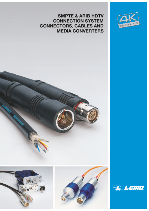
SMPTE & ARIB HDTV
CONNECTION SYSTEM
CONNECTORS, CABLES AND
MEDIA CONVERTERS
Page2
® ®
Precision modular connectors to suit your application
Since it’s creation in Switzerland in 1946 the LEMO Group has been recognized as a global leader of circular Push-Pull con-
nectors and connector solutions. Today LEMO and its affiliated companies, REDEL and COELVER, are active in more than
80 countries with the help of over 40 subsidiaries and distributors.
Over 75’000 connectors
The modular design of the LEMO range provides over 75’000 connectors from miniature ø 3 mm to ø 50 mm, capable of han-
dling cable diameters up to 30 mm and for up to 114 contacts.
This vast portfolio enables you to select the ideal connector configuration to suit almost any specific requirement in most mar-
kets, including medical devices, test and measurement instruments, machinery, audio video broadcast, telecommunications
and military.
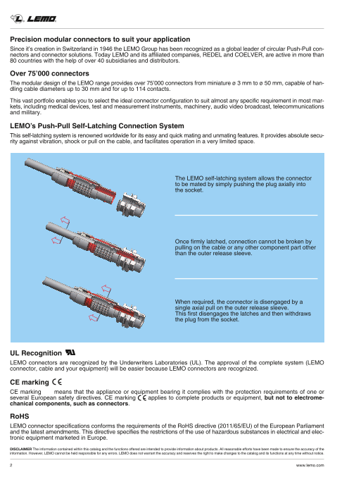
LEMO’s Push-Pull Self-Latching Connection System
This self-latching system is renowned worldwide for its easy and quick mating and unmating features. It provides absolute secu-
rity against vibration, shock or pull on the cable, and facilitates operation in a very limited space.
The LEMO self-latching system allows the connector
to be mated by simply pushing the plug axially into
the socket.
Once firmly latched, connection cannot be broken by
pulling on the cable or any other component part other
than the outer release sleeve.
When required, the connector is disengaged by a
single axial pull on the outer release sleeve.
This first disengages the latches and then withdraws
the plug from the socket.
UL Recognition
LEMO connectors are recognized by the Underwriters Laboratories (UL). The approval of the complete system (LEMO
connector, cable and your equipment) will be easier because LEMO connectors are recognized.
CE marking
CE marking means that the appliance or equipment bearing it complies with the protection requirements of one or
several European safety directives. CE marking applies to complete products or equipment, but not to electrome-
chanical components, such as connectors.
RoHS
LEMO connector specifications conforms the requirements of the RoHS directive (2011/65/EU) of the European Parliament
and the latest amendments. This directive specifies the restrictions of the use of hazardous substances in electrical and elec-
tronic equipment marketed in Europe.
DISCLAIMER The information contained within this catalog and the functions offered are intended to provide information about products. All reasonable efforts have been made to ensure the accuracy of the
information. However, LEMO cannot be held responsible for any errors. LEMO does not warrant the accuracy and reserves the right to make changes to the catalog and its functions at any time without notice.
2 www.lemo.com
Page3
® ®
Table of Contents
HDTV System Overview ...........................................................................................................................................................................................4
LEMO pioneered and set the standard for HDTV ........................................................................................................................................6
3K.93C series
Interconnections ................................................................................................................................................................................................7
Part section showing internal components..............................................................................................................................................8
Technical characteristics................................................................................................................................................................................8
Part number example ......................................................................................................................................................................................9
Models ................................................................................................................................................................................................................10
Insert configurations ......................................................................................................................................................................................12
Fibre optic contact..........................................................................................................................................................................................12
Accessories ......................................................................................................................................................................................................13
Patch panel.......................................................................................................................................................................................................15
Tooling................................................................................................................................................................................................................16
NORTHWIRETM HDTV cables
NORTHWIRE hybrid camera cable according to SMPTE 311 and ARIB standards ............................................................17
Hybrid HDTV fibre optic cable part number..........................................................................................................................................18
Cable assembly ..............................................................................................................................................................................................19
SMPTE 311M standard cable assemblies ............................................................................................................................................22
ARIB cable standard cable assemblies .................................................................................................................................................22
MEERKATTM HD converter
A compact solution for Sony® SD, Grass Valley™ (Thomson®) SD/HD camera based systems ....................................23
Technical characteristics .............................................................................................................................................................................24
List of SD or HD compatible cameras.....................................................................................................................................................24
Local camera power ......................................................................................................................................................................................25
Accessories ......................................................................................................................................................................................................26
SERBALTM converter
SERBALTM - SMPTE Electrical Reconfigurable Bidirectional Alternative Link.............................................................................27
Technical characteristics .............................................................................................................................................................................28
SHACKTM converter
SHACKTM - SMPTE conversion device for singlemode fibre (SC, ST, FC or LC) ...................................................................29
Technical characteristics .............................................................................................................................................................................30
Models ................................................................................................................................................................................................................30
MULTISHACK 3XTM or 6XTM converter
Introduction .......................................................................................................................................................................................................31
MULTISHACK 3XTM - conversion system ..............................................................................................................................................32
Technical characteristics .............................................................................................................................................................................32
MULTISHACK 6XTM - conversion system ..............................................................................................................................................33
Technical characteristics .............................................................................................................................................................................33
HD Z-LINKTM fibre optic link system
HD Z-LINKTM ....................................................................................................................................................................................................34
DISCLAIMER The information contained within this catalog and the functions offered are intended to provide information about products. All reasonable efforts have been made to ensure the accuracy of the
information. However, LEMO cannot be held responsible for any errors. LEMO does not warrant the accuracy and reserves the right to make changes to the catalog and its functions at any time without notice.
www.lemo.com 3
Page4
® ®
HDTV System Overview
CCU SIDE
Outside Broadcast Van Configuration
FXW PUW FMW PUW
CCU SMPTE / ARIB cable
CCU
SERBAL™
HD/SDI
4 way fibre cable
Coax cables
Local 12V source (1.5 A max)
Stadium/building application
PHW SHACK™
FXW PUW FMW
CCU 2 x SC / 2 x ST / 2 x FC / 2 x LC
Singlemode cable or any commonly
CCU Triax HD available duplex cable
CCU MEERKAT™
FXW PUW
12V - 1.5 A max
2 km - SMPTE 311 cable
(for Grass Valley™ systems: 1km - SMPTE 311 cable)
Studio application Wall box INFRASTRUCTURE Wall box
FMW PUW SMPTE / ARIB cable FMW PUW FXW PUW SMPTE / ARIB cable
® ®
SMPTE 311M cable / ARIB BTA S-1005B
CCU HD Z-Link
4 www.lemo.com
Page5
® ®
CAMERA SIDE
SMPTE / ARIB cable FUW
FUW
EDW
HDTV Camera
HDTV Camera
PUW
FXW
EDW
6 way fibre cable
FXG EGG
PHG FGG
Mains power Mains power
SERBAL™
HD/SDI
HDTV Camera
Local 12V source (1.5 A max)
Coax cables
FGW SHACK™
EDW
Local power
HDTV Camera Remote Camera Power
(SMPTE 311 cable)
M MEERKAT™
FUW
Triax HD
Local 12V source (1.5 A max)
HDTV Camera
Wall box INFRASTRUCTURE Wall box
FUW PEW FXW PUW FUW
SMPTE / ARIB cable
HDTV Camera
FUW
EDW
HDTV Camera
SMPTE / ARIB cable
HD Z-Link
HD Camcorder
www.lemo.com 5
Page6
® ®
LEMO pioneered and set the standard for HDTV
The global standard for HDTV fibre connector
LEMO developed the 3K.93C Series connectors in the early stages of the introduction of HDTV, becoming the standard for
high-definition TV.
It is one of the only connectors being used worldwide that complies fully with SMPTE, ARIB and EBU standards for both
signal and cable. LEMO’s 3K.93C connectors are the standard in national and international broadcast companies.
Fast transition to HDTV
Transition to HDTV is easier than ever with LEMO. The wide range of shell styles and termination procedures, for even non-
fibre experts, makes it possible for everyone to be successful in HDTV.
The LEMO 3K.93C connector uses two single-mode fibre contacts, two high voltage contacts, and two signal contacts.
Cable drums and cable assemblies with standard lengths are available off the shelf.
Over 20’000 stainless steel shells mating cycles offered
The rugged stainless steel outer shell of the LEMO 3K.93C connectors ensures a very long product life, when properly clea-
ned. The fibre optic contact can will last many years.
Simple maintenance
The optical contacts are accessible for fast cleaning; an optional simple, lightweight and portable fibre inspection unit helps
the user view the condition of the fibre optic contact to ensure reliable operation.
Highest performance with LEMO standard F2 fibre contact
The advantage of using epoxy and polish contacts is the reliability of the termination and longevity of the connector to assure
a quality signal transmission.
These contacts are very robust and can withstand wide outdoor temperature variations.
Extend the quality of your connection
LEMO offers quality assembly service for HDTV connection systems. The connector assembly is done in-house by qual-
ified personnel.
F2 fibre optic contacts in various dimensions
LEMO now offers 3 choices of F2 ferrule size to fit your fibre dimensions. Fibres are manufactured to about 125 microns,
but in some occasion the fibres might be larger.
LEMO's choice of inner ferrule diameter are fit for 125 µm, 125.5 µm and 126 µm fibres. Designed for use with the LEMO
3K.93C, these contacts can be used directly into any LEMO connector where the F2 contact is used.
Benefits
• Quick disconnect Push-Pull self latching system
• Over 11 shells to meet various application needs
• Stainless steel shell for rugged and harsh environment
• Optional pre-terminated F2 contacts for simple and rapid field assembly
• UL certified connectors
• ARIB (BTA S-1005B), ANSI/SMPTE (304 and 311) and EBU (R100-1999) compatible
DISCLAIMER The information contained within this catalog and the functions offered are intended to provide information about products. All reasonable efforts have been made to ensure the accuracy of the
information. However, LEMO cannot be held responsible for any errors. LEMO does not warrant the accuracy and reserves the right to make changes to the catalog and its functions at any time without notice.
6 www.lemo.com
Page7
® ®
3K.93C Series
The LEMO 3K.93C connectors with keys (W) were developed to meet the critical requirements of the new generation of
digital HDTV cameras.
The main features of this series are as follows:
– Security of the LEMO Push-Pull self-latching system
– Fitted with the standard LEMO F2 fibre optic contacts.
– Conforms to the Japanese ARIB technical report BTA S-1005B, to the ANSI/SMPTE 304 M-1998
and 311M-1998 standards and to the European EBU Technical Recommendation R100-1999.
– Qualified for use in UL approved equipment such as those specified in UL 1419
«Professional Video and Audio Equipment».
– Cabled connectors have obtained the EC Attestation of conformity No: N8 00 03 39058 001
from the German TÜV Product Service.
The 3K.93C series consists of eleven models which will accept cables specific to this application.
It includes the HEAVY DUTY line with stainless steel shells that is guaranteed to at least 20,000 mating cycles and offer
more resistance to heavy wear conditions.
Models (page 10)
Straight plugs Fixed sockets Free sockets
FUW PUW
EDW
FGW PHW
Fixed plugs Fixed sockets
EBW
FXW
PEW
ENW
FMW PBW
Outside Broadcast Van Configuration
HDTV FMW PUW FXW
Camera EDW FUW
CCU
PUW Outside Broadcast Van
Studio Configuration
PUW FXW
HDTV EDW FUW free socket fixed plug
Camera fixed socket straight plug FMWfixed plug
CCU
PUW Camera Control Unit
free socket Patch unit
DISCLAIMER The information contained within this catalog and the functions offered are intended to provide information about products. All reasonable efforts have been made to ensure the accuracy of the
information. However, LEMO cannot be held responsible for any errors. LEMO does not warrant the accuracy and reserves the right to make changes to the catalog and its functions at any time without notice.
www.lemo.com 7
Page8
® ®
Part section showing internal components
6 3 7 8 17 2 3 12 6 16 17 14 15 5
Fixed socket Straight plug
1
shell
1 outer shell
10 split-insert carrier
2 grounding crown
2 latch sleeve
11 anchor with screws
with tag
3
inner shell
12
female LV contact
3 retaining ring
4 front ring
13 earthing body
4 insulator
5 collet nut
14 crimp ring
5 female HV contact
6 insulator
15
collet with gaskets
6 FO contact
7
male HV cont.
16 extended shell
7 O-ring
8 FO contact
17 o-ring
8 male LV contact 9
FO alignment device
5 4 2 1 4 9 7 8 1 17 10 11 13
Technical characteristics
Materials and treatments
Surface treatment (µm)
Component Material (Standard) chrome nickel gold
Cu Ni Cr Cu Ni Cu Ni Au
Outer shell, collet nut Brass (UNS C 38500) 0.5 3 0.3
and oversized collet Stainless steel (AISI 303) without treatment
Special brass 0.5 3
Grounding crown
Stainless steel (AISI 416) without treatment
Special brass 0.5 3 0.3
Latch sleeve
Stainless steel (AISI 416) without treatment
Locking washer Bronze (UNS C 52100) 0.5 3
Hexagonal nut or round nut Brass (UNS C 38500) 0.5 3
Male crimp contact Brass (UNS C 34500) 0.5 3 1.0
Female crimp contact Bronze (UNS C 54400) 0.5 3 1.5
Clips Cu-Be (FS-QQ-C-530) without treatment
Insulator PEEK
Crimping tube Copper (UNS C 18700) 0.5 3
Brass (UNS C 38500) 0.5 3
Other metallic components
Stainless steel (AISI 303) without treatment
O-ring and gaskets Silicone MQ/MVQ, FPM/FKM (Viton®) or Nitril NBR
Electrical Optical
Characteristics Value Standard Characteristics Value Standard Method
Insulation resistance > 1012 Ω IEC 60512-2 test 3a Average insertion loss 0.10 dB IEC 61300-03-04 Insertion
Shell electrical continuity < 1.6 m IEC 60512-2 test 2f fibre 9/125 µm Method BΩ
Contact resistance (signal) < 4.8 mΩ IEC 60512-2 test 2a Return loss fibre 9/125 µm
(UPC) ≥ 45 dB IEC 61300-03-06
Branching
Device Met.
Contact resistance (power) < 3.6 mΩ IEC 60512-2 test 2a
Radiated freq. 30-220 MHz < 30 dBµV/m EN 55022 class B Return loss fibre 9/125 µm Branching
emission (Hand polish)
~30 dB IEC 61300-03-06 Device Met.
freq. 220-1000 MHz < 37 dBµV/m EN 55022 class B
DISCLAIMER The information contained within this catalog and the functions offered are intended to provide information about products. All reasonable efforts have been made to ensure the accuracy of the
information. However, LEMO cannot be held responsible for any errors. LEMO does not warrant the accuracy and reserves the right to make changes to the catalog and its functions at any time without notice.
8 www.lemo.com
Page9
® ®
Mechanical and environmental Vibration
Characteristics Value Standard
Mating durability (Brass+Brass) 10000 cycles IEC 61300-02-02
Mating durability (Brass+Stainless steel) 8000 cycles IEC 61300-02-02
Mating durability (Stainless steel+St. steel) 20000 cycles IEC 61300-02-02
0.1
Damp heat steady state up to 95% at 60°C IEC 61300-02-19
High temperature +80°C IEC 61300-02-18 20 Hz 0.009 G2/Hz
20-60 Hz +9 dB / octave
Low temperature -40°C IEC 61300-02-17 60-200 Hz 0.24 G2/Hz
200-320 Hz -3 dB / octave
Temperature cycling -55°C + 90°C 0.01 320-600 Hz 0.147 G2/Hz
600-2000 Hz -6 dB / octave
Cable retention 1000 N IEC 61300-02-04 2000 Hz 0.014 G2/Hz
duration 180 s / axis
Impact (Method A) 2 m onto concrete floor IEC 61300-02-12
Shock (3 cycles in 2 directions) 100 g, 10-50 ms; 20 g 6-9 ms IEC 61300-02-09 0.001
10 20 50 100 200 500 1K 2K 5K
Water resistance (Depth of 1.8 for 48 h) IP 68 IEC 60529 Frequency (Hz)
Salt spray corrosion test > 144 h IEC 60512-6 test 11f
Part number example
Straight plug and free socket F U W . 3 K . 9 3 C . T L E C 9 6 Z
Variant
Cable ø:
74 = 6.2 to 7.4 mm
96 = 8.9 to 9.5 mm
12 = 11.6 to 12.5 mm
Model Cable fixing type:C = collet adapter
Series: 3K T = cable adapter
Fibre contact:
Type: 93C (page 12)
Housing:
T = stainless steel Insulator: L = PEEK
FUW.3K.93C.TLEC96Z = Straight plug with keys (W), 3K series, mixed type to accept 2 F2 type fibre optic contacts, 2 power and 2 signal
electrical contacts, stainless steel housing, PEEK insulator, female crimp signal contacts, cable fixing type T for 9.2 mm diameter cable,
and nut for fitting a bend relief.
Fixed socket E D W . 3 K . 9 3 C . T L E
Fibre contact:
Model (page 12)
Series: 3K Insulator: L = PEEK
Housing:
Type: 93C T = stainless steel
EDW.3K.93C.TLE = Fixed socket with rear square flange, keys (W), 3K series, mixed type to accept 2 F2 type fibre optic contacts, 2 power
and 2 signal electrical contacts, stainless steel housing, PEEK insulator, male crimp signal contacts.
DISCLAIMER The information contained within this catalog and the functions offered are intended to provide information about products. All reasonable efforts have been made to ensure the accuracy of the
information. However, LEMO cannot be held responsible for any errors. LEMO does not warrant the accuracy and reserves the right to make changes to the catalog and its functions at any time without notice.
www.lemo.com 9
Spectral density acceleration (G2/Hz)
Page10
® ®
3 K 9 3 C
FGW Straight plug, cable adapter, with bend relief FUW Straight plug, cable collet adapter, long shell,
nut for fitting a bend relief with cap
135 maxi ~94
115 maxi ~74
FXW Fixed plug, round flange (4 holes mounting), FMW Fixed plug, round flange (4 holes mounting),
without collet cable adapter, with bend relief
~61 101 maxi
30 ø 3 .
+ 0.1
5 0 30 ø 3 . 5
+ 0.1
0
10 10
Panel cut-out Panel cut-out
EDW Fixed socket with rear square flange, EBW Fixed socket with front square flange,
(4 holes mounting), and earthing tag (4 holes mounting)
ø 3.5 + 0.1 + 0.142.5 0 42.5 ø 3 . 5 0
3 3
22.5 6
Panel cut-out Panel cut-out
DISCLAIMER The information contained within this catalog and the functions offered are intended to provide information about products. All reasonable efforts have been made to ensure the accuracy of the
information. However, LEMO cannot be held responsible for any errors. LEMO does not warrant the accuracy and reserves the right to make changes to the catalog and its functions at any time without notice.
10 www.lemo.com
ø 38
29
ø + 0.1 2 3 .2 0 ø 2 3 .2
+ 0.1
0
ø 19
23 20.6
ø 9.2 ± 0.3
29 ø 38
ø 2 3
+ 0.1
.2 0 ø 2 3 .2
+ 0.1
0
ø 19.5
23 20.6
Page11
® ®
ENW Fixed socket, nut fixing and earthing tag PUW Free socket, cable collet adapter, long shell,
nut for fitting a bend relief with cap
42.5
ø 22.6 + 0.1
6 0
~98
11.3 max
Panel cut-out
PHW Free socket, cable adapter with bend relief PEW Fixed socket, nut fixing, cable adapter,
with bend relief (back panel mounting)
~136 maxi
139 maxi
ø 2 2
+ 0.1
4.5
.6 0
7.5 max Panel cut-out
PBW Fixed socket with rear square flange, (4 holes
mounting, cable adapter, with bend relief
˜136 maxi
ø 3.5 + 0.122.5 0
3 Panel cut-out
DISCLAIMER The information contained within this catalog and the functions offered are intended to provide information about products. All reasonable efforts have been made to ensure the accuracy of the
information. However, LEMO cannot be held responsible for any errors. LEMO does not warrant the accuracy and reserves the right to make changes to the catalog and its functions at any time without notice.
www.lemo.com 1 1
ø 31
29
ø 23.2 + 0.1 0
ø + 0.1 2 4 .2 0
ø 23
23
ø 9.2 ± 0.3
ø 30
ø 2 + 0.1 4 .2 0
ø 23
Page12
® ®
9 3 C Insert configurations
Fibre optic Electrical crimp contacts
contact
Plug insulator Socket insulator
2 2 signal LV male 0.9 20-24 ≤ 42 1000 3
93C fem. 9/125 125
N N
2 power HV male 1.3 14-18 > 6.5 ≤ 600 2250 10
Fibre optic contact
FFS.F2 Male F2 Fibre Optic Contact PSS.F2 Female F2 Fibre Optic Contact
~ 31.2 ~ 31.2 11.9
Ref. Contact Ferrulehole Type Gender Note Ref. Contact
Ferrule
hole Type Gender Note
E FFS.F2.BA2.LCE30 125 µm Crimp Male ● E PSS.F2.BA2.LCE30 125 µm Crimp Female ●
K FFS.F2.BA2.LCT10 125 µm Epoxy Male ● K PSS.F2.BA2.LCT10 125 µm Epoxy Female ●
X FFS.F2.BX2.LCE30 125.5 µm Crimp Male ● X PSS.F2.BX2.LCE30 125.5 µm Crimp Female ●
V FFS.F2.BX2.LCT10 125.5 µm Epoxy Male ● V PSS.F2.BX2.LCT10 125.5 µm Epoxy Female ●
F FFS.F2.BB2.LCE30 126 µm Crimp Male ● F PSS.F2.BB2.LCE30 126 µm Crimp Female ●
N FFS.F2.BB2.LCT10 126 µm Epoxy Male ● N PSS.F2.BB2.LCT10 126 µm Epoxy Female ●
● First choice alternative
● Special order alternative
DISCLAIMER The information contained within this catalog and the functions offered are intended to provide information about products. All reasonable efforts have been made to ensure the accuracy of the
information. However, LEMO cannot be held responsible for any errors. LEMO does not warrant the accuracy and reserves the right to make changes to the catalog and its functions at any time without notice.
12 www.lemo.com
Number of fibre optic contacts
ø 4.4
ø 2
Reference
Contact type for plug
Fibre core/cladding (µm)
Ferrule bore inside ø (µm)
ø 4.4
Number of contacts
Contact function
Contact type for plug
Contact ø (mm)
AWG range
ø 2 Creepage distance
and air clearance (mm)
Working voltage (V rms)
Test voltage (V rms)
Rated current (A)
Page13
® ®
Accessories
GMA Bend relief
Dim. (mm)
Part number
A L
GMA.3B.090.DN 9 42
GMA.4B.011.DN 11 60
Note: The last letter «N» of the part number indicates the colour black of
L the bend relief. For others colour, refer to the table below and replace let-
ter «N» by the letter of the colour required.
Ref. Colour Ref. Colour Ref. Colour
A blue J yellow R red
B white M brown S orange
G grey N black V green
GMF Bend relief with cap for FUW plug
Part number
GMF.3K.085.EANZ
● Material: black ALCRYN®
GMP Bend relief with cap for PUW free socket
Part number
GMP.3K.085.EANZ
● Material: black ALCRYN®
GMF Coloured ring for bend relief with cap
Part number Colour
GMF.3K.265.RG grey
GMF.3K.265.RN black
GMF.3K.265.RR red
GMF.3K.265.RV green
● Material: Silicone
DISCLAIMER The information contained within this catalog and the functions offered are intended to provide information about products. All reasonable efforts have been made to ensure the accuracy of the
information. However, LEMO cannot be held responsible for any errors. LEMO does not warrant the accuracy and reserves the right to make changes to the catalog and its functions at any time without notice.
www.lemo.com 13
ø A
Page14
® ®
B●● Blanking caps
Part number For connector model
BHA.3K.100.EAN BFG.3K.100.EAN BHA.3K.100.715EN BHA.3K.100.EAN FMW, FXW
BRA.3K.200.EAN EDW, PEW
BFG.3K.100.EAN FMW, FXW
BRF.3K.200.EAN PUW
BHA.3K.100.715EN FMW, FXW
BRA.3K.100.715EN EBW, EDW, ENW, PBW, PEW
BRA.3K.200.EAN BRF.3K.200.EAN BRA.3K.100.715EN
● Material: black ALCRYN®
GM● Gaiters
Part number Colour Dimension For connectorL (mm) model
L GMP.3K.140.165PER red 165 PUW
GMP.3K.140.165PEN black 165 PUW
GMF.3K.140.156PEV green 156 FUW
GMF.3K.140.156PEN black 156 FUW
● Material: PVC
BRR Spring loaded dust cap for EDW and EBW
ø A L
Dimensions (mm)
Part number
M A B C L M N
N
BRR.3K.200.PZSG 29 29 23 8.1 3 33.2
Note: On request, this cap is available in black. If so replace the last let-
ter «G» of the part number by «N».
● Material: Polyoxymethylene (POM) grey (or black)
DISCLAIMER The information contained within this catalog and the functions offered are intended to provide information about products. All reasonable efforts have been made to ensure the accuracy of the
information. However, LEMO cannot be held responsible for any errors. LEMO does not warrant the accuracy and reserves the right to make changes to the catalog and its functions at any time without notice.
1 4 www.lemo.com
B
ø C
ø 14 mm
Page15
® ®
Patch panels
PB● Patch panel
2U panel with one row of 6 or 10 plugs or sockets of the
3K.93C Series.
P B G . 3 K . 9 3 C . M W 9 6 0 6
Ref. Colour Ref. Front side connection Ref. Cable ø (mm) Nbof connectors
C beige MW Plug FMW 9606 8.9 to 9.5 6
G grey EW Socket PEW 1206 11.6 to 12.4 6
N black BW Socket PBW 9610 8.9 to 9.5 10
T nat. anod. 1210 11.6 to 12.4 10
Integrated 3U panel with splice tray 2U Rack mounted splice tray
and connector junctions with connector junctions
An integrated panel with built in splice tray and connector junctions for Rack mounted splice tray of 2U height with connector junctions for patch
use where space is limited, either at a wallbox or a patching unit. unit. Can accommodate up to 10 LEMO connectors. The modular design
Up to 3 can be mounted side-by-side to fit in 3U rack dimensions. of the unit along with blanking plates provides opportunity for increasing num-
bers of channels up to 10.
Note: Available on request.
Note: Available on request.
DISCLAIMER The information contained within this catalog and the functions offered are intended to provide information about products. All reasonable efforts have been made to ensure the accuracy of the
information. However, LEMO cannot be held responsible for any errors. LEMO does not warrant the accuracy and reserves the right to make changes to the catalog and its functions at any time without notice.
www.lemo.com 1 5
Page16
® ®
Tooling
DCS.F2.N02.PA Fibre Optic one-click cleaner DCT.F2.125.PA Fibre Optic ferrule cleaner
Insert the one-click cleaner into the insulator and push until an audible “click” This cleaning tool comes with a bush for different cleaning configurations.
is heard. The cleaner uses a mechanical push action to advance an opti- More than 500 cleaning per cleaner. This cleaner is for on-site purposes
cal grade cleaning tape. More than 500 cleaning per cleaner. Product only and should not replace regular maintenance cleaning with cotton buds
includes special LEMO F2 ferrule adaptor. and alcohol.
DCS.F2.035.PN Alignment device tool WST.KI.125.34 Cleaning kit F2 contact
Simple tool with two threaded end for installation/extraction of the F2 Fibre optic cleaning kit of 2 cotton buds, 1 dry and 1 being soaked in IPA
contact alignment device. For use with WST.KI.125.34 kit above. (Isopropyl Alcohol) used for cleaning the fibre optic contacts.
WST.FB.CI1.10US2 Video inspection viewer DCS.3K.175.72LN Cable puller
A portable fibre optic viewer for F2 contact consisting of handset probe, The LEMO cable puller, is a pull through tool that allows passing the
LCD display, ferrule tips for LEMO contacts & software & United States - cable through narrow sections and protects the optical fibre during
AC power supply all in a rugged case. installation.
European power supply version (WST.FB.CI1.10EU2). An optional USB cap-
ture device is also available (part number: WST.FB.CI1.00USB2).
DRV.FO.MOB.LAB3KC Mobile Lab for 3K.93C HD cable tester
with F2 fibre optic contact
This cable tester provides a quick and easy means of checking the func-
tionality of HD hybrid fibre cables and cable systems. A laser source
checks the fibres giving an indication of the attenuation through the whole
cable or cable system, and electrical tests check for continuity of both the
power and control conductors.
Note: Available on request.
DISCLAIMER The information contained within this catalog and the functions offered are intended to provide information about products. All reasonable efforts have been made to ensure the accuracy of the
information. However, LEMO cannot be held responsible for any errors. LEMO does not warrant the accuracy and reserves the right to make changes to the catalog and its functions at any time without notice.
16 www.lemo.com
Page17
® ®
NORTHWIRETM HDTV cables
NORTHWIRE hybrid camera cable according to SMPTE 311 and ARIB standards
This composite cable combines power conductors for TV camera, control wires, and optical fibres for video and audio trans-
mission in a single cable. Specially designed to cope with the heavy demands of outside broadcast.
The cable fully meets the requirements of the SMPTE 311M standard for camera cables.
Primary features and benefits of this cable are:
● High durability construction.
● Excellent flexing and twist capability coping with rough handling by rigging crews.
● Superior load bearing capabilities – can be driven over by trucks whilst in operation.
● High tensile strength.
Commercial quality High quality
SMPTE 311M standard cable ARIB standard cable
CFN.3K.93C.092PNCS CFN.3K.93C.092PNCA
Power wire Optical fibre #1 Power wire Optical fibre #1
Black (x2) Blue Black (x2) Yellow
Signal wire Signal wire Signal wire Signal wire
Red Grey Red Green
Strength member Strength member
Power wire Optical fibre #2 Power wire Optical fibre #2
White (x2) Yellow White (x2) Blue
Cable specification
Core type Power (Aux) Control (Signal) Optic fibre Strength member
Nb of cores 4 2 2 1
Conductor sizes - AWG 20 24 – –
Conductor construction - Nb/mm 19/0.185 7/0.193 – 19/0.330
Mode field diameter - µm – – 8.9 ± 0.8 at 1310 –
Cladding diameter - µm – – 125 ± 1 µm –
Approx. diameter of conductor - mm 0.88 0.58 – 1.75
Nominal insulation thickness - mm 0.41 0.30 – 0.38
Approx. core diameter - mm 1.72 1.22 0.9 2.51
Approx. thickness of tin-coated annealed copper braid - mm 0.127
Nominal thickness of jacket - mm 1.14
Approx. overall diameter - mm 9.2
Approx. net weight - g/m7 137
Max. conductor resistance - (20°C) Ω/km 43 184 (SMPTE) – –
AC withstanding voltage - Vrms at 60 Hz, 1 min 1750 1750 (SMPTE) – –
Min. insulation resistance - (20°) MΩkm 10’000 10’000 – –
UL Listing AWM STYLE 21971
Allowable tension 700N
Optical fibre
Item Wavelength Characteristics Conversion Conversioncondition (km) formula
l = 1.31 µm Less than .8 dB/km up to ≥ 0.4 0.5xLdB≥
Transmission loss
l = 1.31 µm Less than .8 dB/km L < 0.4 0.5x0.4dB≥
DISCLAIMER The information contained within this catalog and the functions offered are intended to provide information about products. All reasonable efforts have been made to ensure the accuracy of the
information. However, LEMO cannot be held responsible for any errors. LEMO does not warrant the accuracy and reserves the right to make changes to the catalog and its functions at any time without notice.
www.lemo.com 17
Page18
® ®
Hybrid HDTV fibre optic cable part number
SMPTE standard
C F N 3 K 9 3 C 0 9 2 P N C S
Version
S = SMPTE 311M
Cable Shielding
C = Tinned copper
Fiber optic Jacket color
N = Black RAL 9005
(other colours
Vendor: N = Northwire on request)
Series Jacket material P = PVC
Type Jacket max ø092 = 9.2 mm
ARIB standard
C F N 3 K 9 3 C 0 9 2 P N C A
Version
A = ARIB standard
Cable Shielding
C = Tinned copper
Fiber optic Jacket color
N = Black RAL 9005
(other colours
Vendor: N = Northwire on request)
Series Jacket material P = PVC
Type Jacket max ø092 = 9.2 mm
DISCLAIMER The information contained within this catalog and the functions offered are intended to provide information about products. All reasonable efforts have been made to ensure the accuracy of the
information. However, LEMO cannot be held responsible for any errors. LEMO does not warrant the accuracy and reserves the right to make changes to the catalog and its functions at any time without notice.
18 www.lemo.com
Page19
® ®
Cable assembly
Part Number Example
Cable M F P 3 K 9 3 C A M 0 2 5 N S
S = SMPTE 311M
A = ARIB
Jacket color
N = Black RAL 9005
(other colours
on request)
Model 1 (table 1)
Cable length
Model 2 (table 1)
M = Meters
C = Centimeters
Cable ø (table 2) K = Kilometers
MFP.3K.93C.AM025NS = 1 FUW plug and 1 PUW socket (key W), 3K.93C series, on a SMPTE 311M screened cable,
25 m length, sheath ø 9.2 mm, black RAL 9005 jacket color, with GMF/GMP bend relief with cap.
Table 1 Table 2
Model Cable ø
Model Sheath ø
1 & 2 (mm)
FUW F A 9.2
FMW M B 2.5
PUW P C 2.8
PEW E D 12.0
PBW B E 16.0
DISCLAIMER The information contained within this catalog and the functions offered are intended to provide information about products. All reasonable efforts have been made to ensure the accuracy of the
information. However, LEMO cannot be held responsible for any errors. LEMO does not warrant the accuracy and reserves the right to make changes to the catalog and its functions at any time without notice.
www.lemo.com 19
Code
Code
Page20
® ®
MFP Outside broadcast cable assembly
Assembly cable with one straight plug (FUW) and one straight socket (receptacle) (PUW), both complete with GMF/GMP bend
relief with cap.
FUW + GMF PUW + GMP
MMP Internal OB van cable assembly
Assembly cable with one fixed plug (FMW) and one straight socket (receptacle) (PUW), both complete with BHA/BRF caps.
BHA FMW PUW BRF
MME Studio/Infrastructure cable assembly
Assembly cable with one fixed plug (FMW) and one straight socket (receptacle) (PEW), complete with BHA cap.
BHA FMW PEW
DISCLAIMER The information contained within this catalog and the functions offered are intended to provide information about products. All reasonable efforts have been made to ensure the accuracy of the
information. However, LEMO cannot be held responsible for any errors. LEMO does not warrant the accuracy and reserves the right to make changes to the catalog and its functions at any time without notice.
20 www.lemo.com