


Precision modular connectors to suit your application
This series of connectors stems from the series 00 and has been specifically developed for applications where the connection
must be guaranteed under very high pressure.
※レモコネクタはモジュール方式のため、共通部品を組み合せることにより様々なコネクタに変えることができます。このため、カタログに掲載されている写真や図は、色、形状などが実物とは微妙に異なっている場合や、写真撮影の方向が一定していない場合がございます。ご注意いただきますようお願いいたします。
このカタログについて
| ドキュメント名 | 小型水中コネクタ 03シリーズ |
|---|---|
| ドキュメント種別 | 製品カタログ |
| ファイルサイズ | 5Mb |
| 登録カテゴリ | |
| 取り扱い企業 | レモジャパン株式会社 (この企業の取り扱いカタログ一覧) |
この企業の関連カタログ


このカタログの内容
Page1
HIGH PRESSURE
CONNECTORS
Page2
® ®
Precision modular connectors to suit your application
Since its creation in Switzerland in 1946 the LEMO Group has been recognized as a global leader of circular Push-Pull
connectors and connector solutions. Today LEMO and its affiliated companies, REDEL and COELVER, are active in more
than 80 countries with the help of over 40 subsidiaries and distributors.
Over 75000 connectors
The modular design of the LEMO range provides over 75000 connectors from miniature ø 3 mm to ø 50 mm, capable of
handling cable diameters up to 30 mm and for up to 114 contacts.
This vast portfolio enables you to select the ideal connector configuration to suit almost any specific requirement in most
markets, including medical devices, test and measurement instruments, machinery, audio video broadcast, telecommuni-
cations and military.
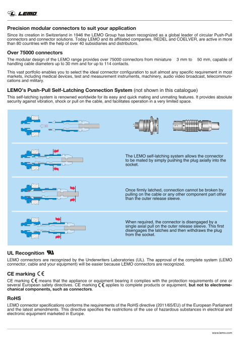
LEMO’s Push-Pull Self-Latching Connection System (not shown in this catalogue)
This self-latching system is renowned worldwide for its easy and quick mating and unmating features. It provides absolute
security against vibration, shock or pull on the cable, and facilitates operation in a very limited space.
The LEMO self-latching system allows the connector
to be mated by simply pushing the plug axially into the
socket.
Once firmly latched, connection cannot be broken by
pulling on the cable or any other component part other
than the outer release sleeve.
When required, the connector is disengaged by a
single axial pull on the outer release sleeve. This first
disengages the latches and then withdraws the plug
from the socket.
UL Recognition
LEMO connectors are recognized by the Underwriters Laboratories (UL). The approval of the complete system (LEMO
connector, cable and your equipment) will be easier because LEMO connectors are recognized.
CE marking
CE marking means that the appliance or equipment bearing it complies with the protection requirements of one or
several European safety directives. CE marking applies to complete products or equipment, but not to electrome-
chanical components, such as connectors.
RoHS
LEMO connector specifications conforms the requirements of the RoHS directive (2011/65/EU) of the European Parliament
and the latest amendments. This directive specifies the restrictions of the use of hazardous substances in electrical and
electronic equipment marketed in Europe.
www.lemo.com
Page3
® ®
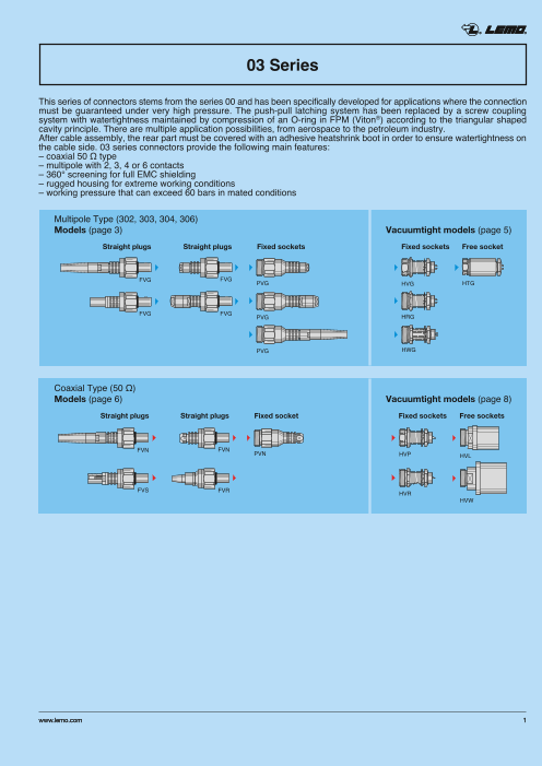
03 Series
This series of connectors stems from the series 00 and has been specifically developed for applications where the connection
must be guaranteed under very high pressure. The push-pull latching system has been replaced by a screw coupling
system with watertightness maintained by compression of an O-ring in FPM (Viton®) according to the triangular shaped
cavity principle. There are multiple application possibilities, from aerospace to the petroleum industry.
After cable assembly, the rear part must be covered with an adhesive heatshrink boot in order to ensure watertightness on
the cable side. 03 series connectors provide the following main features:
– coaxial 50 Ω type
– multipole with 2, 3, 4 or 6 contacts
– 360° screening for full EMC shielding
– rugged housing for extreme working conditions
– working pressure that can exceed 60 bars in mated conditions
Multipole Type (302, 303, 304, 306)
Models (page 3) Vacuumtight models (page 5)
Straight plugs Straight plugs Fixed sockets Fixed sockets Free socket
FVG FVG PVG HVG HTG
FVG FVG PVG HRG
PVG HWG
Coaxial Type (50 Ω)
Models (page 6) Vacuumtight models (page 8)
Straight plugs Straight plugs Fixed socket Fixed sockets Free sockets
FVN FVN PVN HVP HVL
FVS FVR HVR
HVW
www.lemo.com 1
Page4
® ®
Part Numbering System
Plug F V G 0 3 3 0 2 C L A C 2 7
Free socket P V G 0 3 3 0 2 C L L C 2 7
Variant: (page 11)
Cable ø
Collet type:
C = cable collet
E = crimping
K = oversized cable collet
Fixed socket H V G 0 3 3 0 2 C L L P V
V = vacuumtight
Model: (page 3-8) Sealing epoxy resin:
Alignment key: (page 9) P = Araldite® S = Stycast®
(only for multipole)
Contact: (page 10)
Series: 03
Insert configuration: Insulator: L = PEEK
– Multipole (page 10)
– Coax (page 10) Housing: (page 10)
FVG.03.302.CLAC27 = straight plug with key (G) and cable collet, 03 series, multipole type with 2 contacts, outer shell in chrome-plated
brass, PEEK insulator, male solder contacts, C type collet for 2.7 mm diameter cable.
PVG.03.302.CLLC27 = free socket with key (G) and cable collet, 03 series, multipole type with 2 contacts, outer shell in chrome-plated
brass, PEEK insulator, female solder contacts, C type collet for 2.7 mm diameter cable.
HVG.03.302.CLLPV = fixed socket, nut fixing, with key (G), 03 series, multipole type with 2 contacts, outer shell in chrome-plated brass,
PEEK insulator, female solder contacts, sealed with Araldite® epoxy resin.
Part Section Showing Internal Components (multipole)
Straight plug
Fixed socket 1 outer shell
1 outer shell 2 coupling nut9 4 5 3 2 6 8 7 1 1 6 11 5 2 11 10 4 7 11 9 8 3
2 earthing crown 3 collet nut
3 retaining ring 4 centre-piece
4 hexagonal nut 5 insulator
5 locking washer 6 male contact
6 insulator 7 earthing cone
7 female contact 8 collet
8 o-ring 9 compression ring
9 epoxy resin 10 circlip
11 o-ring
2 www.lemo.com
Page5
® ®
Models (multipole type)
Technical Characteristics
Mechanical and Climatical Electrical
Characteristics Value Standard Characteristics Value Standard Section
Endurance > 1000 cycles IEC 60512-5 test 9a Insulation resistance (new) > 1012 Ω IEC 60512-2 test 3a
Humidity up to 95% at 60° C Insulation resistance 3) > 1010 Ω IEC 60512-2 test 3a
Temperature range -20° C, +200° C Shell electrical continuity 5.0 mΩ IEC 60512-2 test 2f
Salt spray corrosion test > 144 h IEC 60512-6 test 11f Shielding at 10 MHz > 100 dB IEC 60169-1-3
Protection index 2) > IP68 IEC 60529 efficiency at 1 GHz > 80 dB IEC 60169-1-3
Resistance to hydrostatic
pressure 2) ~ 60 bars
1) IEC 60512-7 test 14d Contact ø A = 0.5 mm ≤ 8.7 mΩ IEC 60512-2 test 2a
resistance 4) ø A = 0.7 mm ≤ 6.1 mΩ IEC 60512-2 test 2a
Climatical category 20/200/21 IEC 60068-1
Note: Note:
1) in order to perform correctly and withstand the pressure, cable assembly 3) after humidity test: 21 days at 95% RH according to IEC 60068-2.
shall be made according to instruction we recommand. See page 12. 4) after 5000 mating cycles and the salt spray test according to IEC 60512-6
2) For mated plug and socket. test 11 f.
FVG Straight plug, key (G) or key (B), cable collet
Cable ø (mm)
33.7 Part number min. max.
25.5 FVG.03.30l.CLAC27 2.4 2.6
FVG.03.30l.SLAC27 2.4 2.6
FVG.03.30l.CLAC31 2.7 3.0
S 5 S 11 FVG.03.30l.SLAC31 2.7 3.0
Note: l = insert configuration (page 10)
FVG Straight plug, key (G) or key (B), cable collet and nut for fitting a bend relief
Cable ø (mm)
Part number min. max.
38.5
30.3 FVG.03.30l.CLAC27Z 2.4 2.6
FVG.03.30l.SLAC27Z 2.4 2.6
FVG.03.30l.CLAC31Z 2.7 3.0
FVG.03.30l.SLAC31Z 2.7 3.0
S 6 S 11
Note: l = insert configuration (page 10).
The bend relief must be ordered separately (page 11)
FVG Straight plug, key (G) or key (B) and oversize cable collet
Cable ø (mm)
Part number
38.7 min. max.
30.5 FVG.03.30l.CLAK35 3.1 3.5
FVG.03.30l.CLAK40 3.6 4.0
FVG.03.30l.CLAK45 4.1 4.5
FVG.03.30l.CLAK50 4.6 5.0
S 7 S 7 S 11
Note: l = insert configuration (page 10)
Correspond to K type of collet. Also available with nut for fitting a bend relief.
www.lemo.com 3
ø 11.8
ø 11.8 ø 11.8
Page6
® ®
FVG Straight plug, key (G) for cable crimping
Cable ø (mm)
34.7 Part number max.
26.5 FVG.03.30l.CLAE44 4.3
FVG.03.30l.SLAE44 4.3
FVG.03.30l.CLAE52 5.1
S 11 FVG.03.30l.SLAE52 5.1
Note: l = insert configuration (page 10)
PVG Free socket, key (G) and cable collet
36.7
32.7
Cable ø (mm)
Part number min. max.
PVG.03.30l.CLLC27 2.4 2.6
S 5 S 11 PVG.03.30l.CLLC31 2.7 3.0
Note: l = insert configuration (page 10)
PVG Free socket, key (G), cable collet and nut for fitting a bend relief
41.5
37.5 Cable ø (mm)
Part number min. max.
PVG.03.30l.CLLC27Z 2.4 2.6
PVG.03.30l.CLLC31Z 2.7 3.0
S 6 S 11
Note: l = insert configuration (page 10).
The bend relief must be ordered separately (page 11)
PVG Free socket, key (G) and oversize cable collet
Cable ø (mm)
Part number min. max.
52.7
48.7 PVG.03.30l.CLLK35 3.1 3.5
PVG.03.30l.CLLK40 3.6 4.0
PVG.03.30l.CLLK45 4.1 4.5
PVG.03.30l.CLLK50 4.6 5.0
S 7 S 7 S 11
Note: l = insert configuration (page 10)
Correspond to K type of collet. Also available with nut for fitting a bend relief.
4 www.lemo.com
ø 11.8
ø 11.8 ø 11.8ø 11.8
Page7
® ®
Vacuumtight models (multipole type)
These sockets models allow the device on which they are fitted to reach a protection index of IP68 as per IEC 60529. They
are fully compatible with plugs of the same series and are widely used for portable radios, military, laboratory equipment,
aviation, etc.
These models are identified by a letter «P» or «S» at the last but one character of the reference. The Stycast® sealant can
be used over a larger temperature range than the Araldite® sealant.
Vaccumtight models are identified by an additional letter «V» at the end of the part number (certificate on request). Epoxy
resin is used to seal these models.
Technical Characteristics
Mechanical and Climatical
Characteristics Value Standard Characteristics Value Standard
Endurance > 1000 cycles IEC 60512-5 test 9a Climatical category 20/80/21 IEC 60068-1
Humidity up to 95% at 60° C Leakage rate (He) 1) < 10-7 mbar.l.s-1 IEC 60512-7 test 14b
Temperature range -20° C, +100° C Max. operating pressure 2) 60 bars IEC 60512-7 test 14d
Salt spray corrosion test > 144h IEC 60512-6 test 11f Note: 1) only for vacuumtight models. 2) this value corresponds to the
maximum allowed pressure difference for the assembled socket.
HVG Fixed socket, key (G) or key (B), round flange, nut fixing, vacuumtight
22
6 S 9 Part number Sealing resin
HVG.03.30l.CLLPV Araldite®
HVG.03.30l.SLLPV Araldite®
S 9 6.5 maxi HVG.03.30l.CLLSV Stycast® Panel cut-out (page 11)
HVG.03.30 .SLLSV Stycast® Note: l = insert l configuration (page 10)
HWG Fixed socket, key (G), hexagonal flange, nut fixing, vacuumtight
21
S 9 S 11 6
Part number Sealing resin
®
S 6.3 6.5 maxi HWG.03.30l.CLLPV Araldite Panel cut-out (page 11)
HWG.03.30 ® Note: l = insert l.CLLSV Stycast configuration (page 10)
HRG Fixed socket, key (G), hexagonal flange, nut fixing, no flats on fixing thread, vacuumtight
22
S 11 Part number Sealing resin
6
HRG.03.30l.CLLPV Araldite®
HRG.03.30l.SLLPV Araldite®
® Panel cut-out (page 11)
S 9 6.5 maxi HRG.03.30l.CLLSV Stycast
HRG.03.30l.SLLSV Stycast® Note: l = insert configuration (page 10)
www.lemo.com 5
ø 10.2 ø 10.2 ø 10.2
M7x0.5 M7x0.5 M7x0.5
ø 11.8 ø 11.8 ø 11
Page8
® ®
HTG Fixed socket, key (G), nut fixing, long shell
26 S 9
S 9 Part number Sealing resin Panel cut-out (page 11)
HTG.03.30l.CLLSV Stycast® Note: l = insert configuration (page 10)
Models (coaxial type)
Technical Characteristics
Mechanical and Climatical Electrical
Characteristics Value Standard Characteristics Value Standard Section
Endurance > 1000 cycles IEC 60512-5 test 9a Insulation resistance (new) > 1012 Ω IEC 60512-2 test 3a
Humidity up to 95% at 60° C Insulation resistance 3) > 1010 Ω IEC 60512-2 test 3a
Temperature range -20° C, +200° C Shell electrical continuity 5.0 mΩ IEC 60512-2 test 2f
Salt spray corrosion test > 144 h IEC 60512-6 test 11f Shielding at 10 MHz > 100 dB IEC 60169-1-3
Protection index 2) > IP68 IEC 60529 efficiency at 1 GHz > 80 dB IEC 60169-1-3
Resistance to hydrostatic Contact ø A = 0.5 mm ≤ 8.7 mΩ IEC 60512-2 test 2a
2) ~ 60 bars 1)pressure IEC 60512-7 test 14d resistance 4) ø A = 0.7 mm ≤ 6.1 mΩ IEC 60512-2 test 2a
Climatical category 20/200/21 IEC 60068-1 Max. working frequency 500 MHz For coaxial type
Note: Note:
1) in order to perform correctly and withstand the pressure, cable assembly 3) after humidity test: 21 days at 95% RH according to IEC 60068-2.
shall be made according to instruction we recommand. See page 12. 4) after 5000 mating cycles and the salt spray test according to IEC 60512-6
2) For mated plug and socket. test 11 f.
FVN Straight plug, cable collet
Part number Cable group
29.5
21.2 FVN.03.250.CLAC27 4
FVN.03.250.SLAC27 4
FVN.03.250.CLAC31 3
S 4.5 S 11 FVN.03.250.SLAC31 3
Cable assembly (page 12)
6 www.lemo.com
ø 10.2
M7x0.5
ø 11.8
ø 11
Page9
® ®
FVN Straight plug, cable collet and nut for fitting a bend relief
38.5
Part number Cable group
30.3
FVN.03.250.CLAC27Z 4
FVN.03.250.SLAC27Z 4 Cable assembly (page 12)
S 6 S 11 FVN.03.250.CLAC31Z 3 Note: The bend relief must
FVN.03.250.SLAC31Z 3 be ordered separately (page 11).
FVS Straight plug for cable crimping
35.3
26.5 Part number Cable group
FVS.03.250.CLAE24 1
FVS.03.250.CLCE24 1
S 5.5 S 11 FVS.03.250.CLCE31 3-4
Cable assembly (page 12)
FVR Straight plug with brazing ferrule
32.9
Cable ø (mm)
24.6 Part number max.
FVR.03.250.SLAV16B 1.55
FVR.03.250.SLAV20B 1.95
S 11 Cable assembly (page 12)
Note: The shell of the connector is in stainless steel AISI 316L.
PVN Free socket and cable collet
36.7
32.7 Part number Cable group
PVN.03.250.CLLC27 4
PVN.03.250.CLLC31 3
S 4.5 S 11 Cable assembly (page 12)
Note: Also available with nut for fitting a bend relief (page 11).
www.lemo.com 7
ø 11.8 ø 11.8 ø 11.8
ø 11.8
Page10
® ®
Vacuumtight models (coaxial type)
These sockets models allow the device on which they are fitted to reach a protection index of IP68 as per IEC 60529. They
are fully compatible with plugs of the same series and are widely used for portable radios, military, laboratory equipment,
aviation, etc.
These models are identified by a letter «P» or «S» at the last but one character of the reference. The Stycast® sealant can
be used over a larger temperature range than the Araldite® sealant.
All these models are available in a watertight or vacuumtight version. Vaccumtight models are identified by an additional
letter «V» at the end of the part number (certificate on request). Epoxy resin is used to seal these models.
Technical Characteristics
Mechanical and Climatical
Characteristics Value Standard Characteristics Value Standard
Endurance > 1000 cycles IEC 60512-5 test 9a Climatical category 20/80/21 IEC 60068-1
Humidity up to 95% at 60° C Leakage rate (He) 1) < 10-7 mbar.l.s-1 IEC 60512-7 test 14b
Temperature range -20° C, +100° C Max. operating pressure 2) 60 bars IEC 60512-7 test 14d
Salt spray corrosion test > 144h IEC 60512-6 test 11f Note: 1) only for vacuumtight models. 2) this value corresponds to the
maximum allowed pressure difference for the assembled socket.
HVR Fixed socket, hexagonal flange, nut fixing, vacuumtight
Part number Sealing resin
21
S 11 6 HVR.03.250.CLLPV Araldite®
HVR.03.250.SLLPV Araldite®
HVR.03.250.CLLSV Stycast®
®
S 9 6.5 maxi HVR.03.250.SLLSV Stycast
Panel cut-out (page 11)
HVP Fixed socket, round flange, nut fixing, vacuumtight
21
6 S 9
Part number Sealing resin
HVP.03.250.CLLPV Araldite®
S 9 6.5 maxi HVP.03.250.CLLSV Stycast®
Panel cut-out (page 11)
HVL Free socket, for device overmolding
24.2
Part number
S 11 HVL.03.250.NLL
8 www.lemo.com
ø 10.2 ø 10.2
M7x0.5 M7x0.5
M10x0.75
ø 13.9
ø 11 ø 11.8
Page11
® ®
HVW Free socket, for device overmolding, large shell
28
18
Part number
HVW.03.250.NLL
S 11
Note: Vacuumtightness is achieved after customer overmolding.
Alignment Key
Alignment Key and Polarized Keying System for Multipole Types
03 series connector model part numbers are composed of three letters. The LAST LETTER indicates the key position and
the contact type (male or female).
Front view of a socket Series Contact type
Nb of
α keys
03 Plug Socket
G 1 0° male female
B 2 α 60° male female
Insert configuration
Coaxial, multipole
1 4 4 1
2 3 3 2
Male solder contacts Female solder contacts
Coaxial
1 250 03 0.7 1-3-4 – 50 2.1 2.10 4.0
Multipole
2 302 03 0.5 – 30 – 1.0 0.95 5.0
Multipole
3 303 03 0.5 – 30 – 0.8 0.95 3.0
Multipole
4 304 03 0.5 – 30 – 0.8 0.95 2.0
Multipole
6 306 03 0.35 – 30 – 0.7 0.95 1.7
Note: 1) Test voltage measured according to IEC 60512-2 test 4a standard.
www.lemo.com 9
Key
Angles
M10x0.75
ø 19.9
Reference
Series
Contact ø (mm)
Cable group
AWG max.
Impedance (Ω)
Test voltage (kV rms)1)
Contact-contact
Test voltage (kV rms)1)
Contact-shell
Rated current (A)1)
Page12
® ®
H ousings
Outer shell and collet nut Latch sleeve + earthing crown Other metallic components
Ref. Remarks Note
Material Surf. treatment Material Surf. treatment Material Surf. treatment
C Brass chrome brass/bronze nickel brass nickel For multipole and coaxial l
S Stainless steel – brass/bronze nickel brass nickel For multipole and coaxial l
Note: detailed characteristics of these materials and treatments are presented in the Unipole-Multipole catalogue.
l First choice alternative
Special order alternative
Contacts
Ref. Contact type Remarks
A Male solder For multipole and coaxial
C Male crimp For coaxial
L Female solder For multipole or coaxial type sockets
Variant
Bend relief for models with collet
Need to be ordered
Collet Dim . (mm)Need to be ordered Cable ø
Type Code separately max. min.
C 27 GMB.00.025.DG 2.8 2.5
03 C 31 GMB.00.028.DG 3.1 2.8
Z
C 27 GMD.00.025.DG 2.8 2.5
C 31 GMD.00.028.DG 3.1 2.8
K 35 GMA.0B.030.DG 3.4 3.0
K 40 GMA.0B.035.DG 3.9 3.5
Z
K 45 GMA.0B.040.DG 4.4 4.0 Note: The «GMD» are thin bend reliefs (for very flexible cables).
K 50 GMA.0B.045.DG 5.2 4.5 The last letter «G» of the part number indicates the grey colour of the bend relief.
Accessories
For accessories and tooling, please contact us.
10 www.lemo.com
Ref.
Page13
® ®
Tooling
DCG Spanner for hexagonal nut
50
Part number Part numberof the nut
ø 14 DCG.91.149.0TN GEA.00.240.LN
l Material: Blackened steel
DCP Flat spanners for collet nut
N M
Dimensions
Part number L M N S1
DCP.99.045.TC 70 2 10.5 4.5
DCP.99.050.TC 78 2 12.6 5.0
DCP.99.055.TC 78 2 12.6 5.5
DCP.99.060.TC 78 2 12.6 6.0
S1
l Material: Chrome-plated steel
DPE Crimping tool with die (coaxial connectors)
Part number Cablegroup
DPE.99.123.1K 1
DPE.99.123.8K 2-3-4
DPN Dies
A Die dimension
L A Part number Cablegroup For contacts For shield
A B L A B
DPN.99.123.1K 1 1.29 0.91 2.0 3.10 2.70
B DPN.99.123.8K 2-3-4 1.29 0.91 2.0 3.80 3.30
for contacts for shield
l Dies material: Blackened steel
www.lemo.com 11
L
40
B
S1
Page14
® ®
Panel cut-outs
Panel Cut-outs
HWG HRG, HTG, HVG,
13 HVP, HVR 13
6.4 +0.1 +0.1 +0.1 0 ø 7.1 0 ø 7.1 0
Mounting nuts torque
Component Torque (Nm)
Retaining nut 0.25
Hexagonal nut 2.00
Coupling nut 2.00 1N = 0.102 kg
Cable assembly
Assembly instructions
In order to ensure the sealing of plugs and sockets on the cable side, it is imperatively necessary to complete their assembly
by realizing it with an adapted technique.
We recommend the fitting of an heatshrink boot with inner melting coating of type ATUM (manufactured by the RAYCHEM
company) or similar.
This heatshrink boot is not provided with the connector. Please consult us.
Cable stripping lengths
Connector Cable stripping
L lengths (mm)
T Series Type L S T
250 0.7 6 2.5 3
03 302/303/304 0.5 6 2.5 3S Note: the tolerances on these dimensions are:
302/303/3041) 0.5 13.5 – 2.5 L: ± 0.5 mm; S: ± 0.5 mm; T: ± 0.2 mm.1) for FVG model with cable crimping.
Recommended coaxial cables
Recommended cables for coaxial types
Cable Standard Imp.
group MIL-C-17 IEC 96-2 CCTU 10-01A Reference (Ω)
KX 3A CCX.50.RG1.74AU27N
3 RG.174 A/U 50.2.1 50 ± 2 Ω
KX 38 CCX.50.RG1.74U25N
1 RG.178 B/U 50.1.1 KX 21A CCX.50.RG1.78BU18M 50 ± 2 Ω
4 RG.188 A/U 50.2.3 CCX.50.RG1.88AU24B 50 ± 2 Ω
1 RG.196 A/U 50.1.2 CCX.50.RG1.96AU20B 50 ± 2 Ω
4 RG.316 /U 50.2.2 KX 22A CCX.50.RG3.16BU26M 50 ± 2 Ω
12 www.lemo.com
ø contact A
(mm)
Page15
® ®
Product safety notice
PLEASE READ AND FOLLOW ALL INSTUCTIONS CAREFULLY AND CONSULT ALL RELEVENT NATIONAL AND
INTERNATIONAL SAFETY REGULATIONS FOR YOUR APPLICATION.
IMPROPER HANDLING, CABLE ASSEMBLY, OR WRONG USE OF CONNECTORS CAN RESULT IN HAZARDOUS
SITUATIONS.
1. SHOCK AND FIRE HAZARD
Incorrect wiring, the use of damaged components, presence of foreign objects (such as metal debris), and / or residue
(such as cleaning fluids), can result in short circuits, overheating, and / or risk of electric shock.
Mated components should never be disconnected while live as this may result in an exposed electric arc and local
overheating, resulting in possible damage to components.
2. HANDLING
Connectors and their components should be visually inspected for damage prior to installation and assembly. Suspect
components should be rejected or returned to the factory for verification.
Connector assembly and installation should only be carried out by properly trained personnel. Proper tools must be used
during installation and / or assembly in order to obtain safe and reliable performance.
3. USE
Connectors with exposed contacts should never be live (or on the current supply side of a circuit). Under general
conditions voltages above 30 VAC and 42 VDC are considered hazardous and proper measures should be taken to
eliminate all risk of transmission of such voltages to any exposed metal part of the connector.
4. TEST AND OPERATING VOLTAGES
The maximum admissible operating voltage depends upon the national or international standards in force for the
application in question. Air and creepage distances impact the operating voltage; reference values are indicated in the
catalog however these may be influenced by PC board design and / or wiring harnesses.
The test voltage indicated in the catalog is 75% of the mean breakdown voltage; the test is applied at 500 V/s and the
test duration is 1 minute.
5. CE MARKING
CE marking means that the appliance or equipment bearing it complies with the protection requirements of one or
several European safety directives.
CE marking applies to complete products or equipment, but not to electromechanical components, such as
connectors.
6. PRODUCT IMPROVEMENTS
The LEMO Group reserves the right to modify and improve to our products or specifications without providing prior
notification.
7. WARNING (Prop 65 State of California)
This product may contain one or more substances or chemicals known to the state of California to cause cancer.
Disclaimers
LEMO works constantly to improve the quality of its products; the information and illustrations figuring in this document may
therefore vary and are not binding. In any case, LEMO makes no specific warranty of merchantability, fitness for a particu-
lar purpose, third party components as such or included in assembly, non-infringement, title, accuracy, completeness, or
security. The user is fully responsible for his products and applications using LEMO component.
In no event shall LEMO, its affiliates, officers, agents or employees be liable for any incidental, indirect, special or consequen-
tial damages in connection with the products or services provided by LEMO, including (without limitation) loss of profits
or revenues, interruption of business, loss of use of the products or any associated equipment, materials, components or
products, damages to associated equipment or in combination with other components, materials.
Reproduction of significant portions of LEMO information in LEMO data books or data sheets is permissible only if repro-
duction is without alteration and is accompanied by all associated warranties, conditions, limitations, and notices. LEMO is
not responsible or liable for such altered documentation. Information of third parties may be subject to additional restrictions.
www.lemo.com
Page16
LEMO HEADQUARTERS
SWITZERLAND
LEMO SA
Chemin des Champs-Courbes 28 - P.O. Box 194 - CH-1024 Ecublens
Tel. (+41 21) 695 16 00 - Fax (+41 21) 695 16 02 - e-mail: info@lemo.com
LEMO SUBSIDIARIES
AUSTRIA JAPAN
LEMO Elektronik GesmbH LEMO Japan Ltd
Lemböckgasse 49/E6-3 2-7-22, Mita,
1230 Wien Minato-ku, Tokyo, 108-0073
Tel: (+43 1) 914 23 20 0 Tel: (+81 3) 54 46 55 10
Fax:(+43 1) 914 23 20 11 Fax: (+81 3) 54 46 55 11
sales@lemo.at lemoinfo@lemo.co.jp
BRAZIL MIDDLE EAST
LEMO Latin America Ltda LEMO Middle East Gen. Trad. LLC
Av. José Rocha Bonfim, Concorde Tower 6th Floor,
214 Salas 224 / 225 Dubai Media City, P.O. Box 126732
Condomínio Praça Capital Dubai, United Arab Emirates
Ed. Chicago Tel: +971 55 222 36 77
Campinas / SP - Brasil 13080-650 info-me@lemo.com
Tel: +55 (11) 98689 4736
info-la@lemo.com NETHERLANDS / BELGIUM
LEMO Connectors Benelux
CANADA De Trompet 1060
LEMO Canada Inc 1967 DA Heemskerk
44 East Beaver Creek Road, unit 20 Tel. (+31) 251 25 78 20
Richmond Hill, Ontario L4B 1G8 Fax (+31) 251 25 78 21
Tel: (+1 905) 889 56 78 info@lemo.nl
Fax: (+1 905) 889 49 70
info-canada@lemo.com NORWAY / ICELAND
LEMO Norway A/S
CHINA / HONG KONG Soerumsandvegen 69,
LEMO Electronics (Shanghai) Co., Ltd 1920 Soerumsand
First Floor, Block E, Tel: (+47) 22 91 70 40
18 Jindian Road, Pudong Fax: (+47) 22 91 70 41
Shanghai, China, 201206 info-no@lemo.com
Tel: (+86 21) 5899 7721
Fax: (+86 21) 5899 7727 SINGAPORE
cn.sales@lemo.com LEMO Asia Pte Ltd
4 Leng Kee Road,
DENMARK #06-09 SiS Building
LEMO Denmark A/S Singapore 159088
Nybrovej 97 Tel: (+65) 6476 0672
2820 Gentofte Fax: (+65) 6474 0672
Tel: (+45) 45 20 44 00 sg.sales@lemo.com
Fax: (+45) 45 20 44 01
info-dk@lemo.com SPAIN / PORTUGAL
IBERLEMO SAU
FRANCE Brasil, 45, 08402 Granollers
LEMO France Sàrl Barcelona
24/28 Avenue Graham Bell Tel: (+34 93) 860 44 20
Bâtiment Balthus 4 Fax: (+34 93) 879 10 77
Bussy Saint Georges info-es@lemo.com
77607 Marne la Vallée Cedex 3
Tel: (+33 1) 60 94 60 94 SWEDEN / FINLAND
Fax: (+33 1) 60 94 60 90 LEMO Nordic AB
info-fr@lemo.com Gunnebogatan 30, Box 8201
163 08 Spånga
GERMANY Tel: (+46 8) 635 60 60
LEMO Elektronik GmbH Fax: (+46 8) 635 60 61
Hanns-Schwindt-Str. 6 info-se@lemo.com
81829 München
Tel: (+49 89) 42 77 03 SWITZERLAND
Fax: (+49 89) 420 21 92 LEMO Verkauf AG
info@lemo.de Grundstrasse 22 B, 6343 Rotkreuz
Tel: (+41 41) 790 49 40
HUNGARY ch.sales@lemo.com
REDEL Elektronika Kft
Nagysándor József u. 6-12 UNITED KINGDOM
1201 Budapest LEMO UK Ltd
Tel: (+36 1) 421 47 10 12-20 North Street, Worthing,
Fax: (+36 1) 421 47 57 West Sussex, BN11 1DU
info-hu@lemo.com Tel: (+44 1903) 23 45 43
lemouk@lemo.com
ITALY
LEMO Italia srl USA
Viale Lunigiana 25 LEMO USA Inc
20125 Milano P.O. Box 2408
Tel: (+39 02) 66 71 10 46 Rohnert Park, CA 94927-2408
Fax: (+39 02) 66 71 10 66 Tel: (+1 707) 578 88 11
sales.it@lemo.com (+1 800) 444 53 66
Fax:(+1 707) 578 08 69
info-US@lemo.com
LEMO DISTRIBUTORS
ARGENTINA, AUSTRALIA, BRAZIL, CHILE, COLOMBIA, CZECH REPUBLIC,
GREECE, INDIA, ISRAEL, NEW ZEALAND, PERU, POLAND, RUSSIA,
SOUTH AFRICA, SOUTH KOREA, TAIWAN, TURKEY, UKRAINE
www.lemo.com
© CAT.03.LEN.P1008, updated November 2016