


COMPACT MULTIPOLE CONNECTORS
※レモコネクタはモジュール方式のため、共通部品を組み合せることにより様々なコネクタに変えることができます。このため、カタログに掲載されている写真や図は、色、形状などが実物とは微妙に異なっている場合や、写真撮影の方向が一定していない場合がございます。ご注意いただきますようお願いいたします。
このカタログについて
| ドキュメント名 | 耐振動・耐衝撃コネクタ Fシリーズ |
|---|---|
| ドキュメント種別 | 製品カタログ |
| ファイルサイズ | 5.9Mb |
| 登録カテゴリ | |
| 取り扱い企業 | レモジャパン株式会社 (この企業の取り扱いカタログ一覧) |
この企業の関連カタログ


このカタログの内容
Page1
COMPACT MULTIPOLE
CONNECTORS
Page2
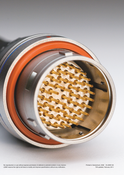
No reproduction or use without express permission of editorial or pictorial content, in any manner. Printed in Switzerland, 2008 © LEMO SA
LEMO reserve the right at all times to modify and improve specifications without any notification. Pdf updated, February 2011
Page3
® ®
Table of Contents
General production programme ....................................................................................................page 2
Main characteristics and types...............................................................................................................2
Series and types ......................................................................................................................................3
LEMO’s push-pull self-latching connection system.............................................................................4
F series production program ..................................................................................................................4
General characteristics ...........................................................................................................................5
Selection of shell materials, degrees of protection (IP code) .............................................................5
Selection of contact types (crimp, print, fibre optic)............................................................................6
F Series ...................................................... Interconnections.........................................................................................................................................8
Part numbering system ..............................................................................................................................9
Part section showing internal components ....................................................................................................9
Technical characteristics ...........................................................................................................................10
Metal housing models ..............................................................................................................................11
Watertight PCB models............................................................................................................................15
Models for Fibre Optic..............................................................................................................................16
Alignment key...........................................................................................................................................17
Insert configuration ..................................................................................................................................18
Housings, contacts, cable fixing...............................................................................................................20
Variant ......................................................................................................................................................21
LEMO F1 ECU systems connectors ........................................................................................................22
Spare parts ............................................... Crimp contacts .........................................................................................................................................24
F7 fibre optic contacts..............................................................................................................................25
Locking washers, hexagonal nuts, notched nuts .....................................................................................25
Conical nuts .............................................................................................................................................26
Accessories.............................................. Caps.........................................................................................................................................................28
Heatshrink boot, insulating washers ........................................................................................................29
Tooling ........................................................ Spanners, taps, manual and pneumatic crimping tools ...........................................................................30
Positioners, extractor for crimp contact ....................................................................................................31
Banding tool, retention testing tool ..........................................................................................................32
Fibre Optic Tooling ............................... Complete workstation for F7 fibre optic contact.......................................................................................32
Crimping tool, epoxy curing oven, polishing tool .....................................................................................32
Fibre inspection microscope, microscope adaptor, F7 contact alignment device tool.............................33
Panel Cut-Outs........................................ Mounting nut torque .................................................................................................................................33
PCB Drilling Pattern ............................. Fixed socket with straight print contact ....................................................................................................34
Fixed socket with elbow print contact ......................................................................................................35
Technical Characteristics.................. Outer shell................................................................................................................................................37
Insulator ...................................................................................................................................................37
Electrical contact ......................................................................................................................................38
Test voltage ..............................................................................................................................................39
Rated current ...........................................................................................................................................40
Assembly instructions ..............................................................................................................................41
Technical tables........................................................................................................................................42
Product safety notice................................................................................................................................44
www.lemo.com 1
Page4
® ®
General Production Programme
Connectors Unipole from 2 to 150 Amps Patch Panels All audio-video and HDTV applications
Coaxial 50 and 75 Ω
Coaxial 50 Ω (NIM-CAMAC) Adaptors For BNC, C, UHF, N, CINCH, GEN-RADIO connectors
Coaxial 50 Ω for frequency → 12 GHz For TNC, SMA connectors
Multicoaxial 50 and 75 Ω
● Multipole from 2 to 68 contacts Accessories Insulator for crimp contacts
Multipole up to 106 contacts ● Crimp contacts
High Voltage 3, 5, 8, 10, 15, 30 and 50 kV cc Coaxial contacts
Multi High Voltage 3, 5, and 10 kV cc Triaxial contacts
Triaxial 50 and 75 Ω ● Fibre optic contacts
Quadrax Fluidic contactss
Mixed: High Voltage (HV) + Low Voltage (LV) ● Caps
Mixed: Coax + LV and Triax + LV Bend relief
Thermocouple and multithermocouple ● Heatshrink boot
Fibre optic singlemode and multimode ● Washers
● Multi Fibre optic ● Nuts
● Mixed: fibre optic + LV
Mixed: fibre optic + HV + LV Tooling Assembly tool
Fluidic and Multifluidic ● Crimping tools
Mixed: fluidic + LV ● Positioners
Subminiature ● Extractors
Miniature ● Banding tool●
● Sockets for printed circuit board ● Fibre optic termination workstation and tools
Remote handling shell On request Connectors with special housing
● Watertight socket Special mixed configuration
Hermaphroditic shell Custom design
Rectangular connectors Assembly onto cable
Sealed (pressure and/or vacuum) socket
Plastic shell ● Connectors, accessories and tools found in this catalogue.
● With aluminium outer shell
With stainless steel outer shell
With microswitch
Main Characteristics and Types
Series Standard Watertight Keyed Keyed CompactWatertight keyed Hermaphroditic Rectangular Screw
01 / 00 (unipole) 0E to 6E 00 (multipole) 0K to 5K FF to 5F SH / MH RR / 0R / 1R 03
00 (NIM-CAMAC) 3T 0B to 5B 2N to 5N 0V to 5V
05 / R0 / 1D 4M 2G / 5G 0W to 5W
0S to 6S 2U to 5U
0A / 4A / 2C 0M-1M-2M
1Y-3Y-6Y
Latching Push-Pull Screw
Key Stepped insert Key (G) Key (N) or other Hermaphroditic Key or or other key-way code key-way code shell Key G or A stepped insert
Shell Metal or plastic Metal Metal or plastic Metal Plastic Metal
Insert Stepped insert or cylindrical Cylindrical Stepped insert Rectangular Stepped insert or cylindrical
Contact
termination Solder or print Solder, crimp or print Crimp or print
Solder, Solder
crimp or print Crimp or print crimp or print
Contact Coaxial, triaxial, unipole, multipole Multipole, fibre optic, Multipole, HV, Multipole,
type HV, quadrax, fluidic, thermocouple HV, fluidic, thermocouple Multipole, fibre optic coaxial, fluidic coaxial, triaxial
LV + coax, LV + coax,Mixed LV + coax, LV + HV LV + coax, LV + triax, LV + HV, LV + FO LV + HV, LV + triax, config. LV + FO, LV + fluidic LV + fluidic LV + FO, LV + fluidic
2 www.lemo.com
Page5
® ®
Series and Types
Types
Series
01 ●
00 ● ● ● ●
05 ●
R0 ●
0A ● ●
0S ● ● ● ● ● ●
1S ● ● ● ● ● ● ●
2S ● ● ● ● ● ● ● ● ●Standard
3S ● ● ● ● ● ● ● ● ● ●
4S ● ● ● ● ● ● ● ● ● ● ●
5S ● ● ● ● ● ● ● ●
6S ● ● ●
1D ●
2C ● ●
4A ●
1Y-3Y-6Y ●
0E ● ● ● ● ● ●
1E ● ● ● ● ● ● ●
2E ● ● ● ● ● ● ● ● ●
3E ● ● ● ● ● ● ● ● ● ●
Watertight 4E ● ● ● ● ● ● ● ●
5E ● ● ● ● ● ●
6E ● ● ●
3T ● ●
4M ● ●
00 ● ● ●
0B ● ● ● ●
1B ● ● ● ● ●
XB ●
2B ● ● ● ● ● ● ● ● ● ●Keyed
3B ● ● ● ● ● ● ● ● ●
4B ● ● ● ● ● ● ● ● ●
5B ● ● ● ● ● ● ● ●
2G ●
5G ●
0K ● ● ●
1K ● ● ● ● ●
2K ● ● ● ● ● ● ● ● ● ● ●
Keyed
watertight 3K ● ● ● ● ● ● ● ● ● ●
4K ● ● ● ● ● ● ● ● ●
5K ● ● ● ● ● ● ● ●
2N to 5N ● ● ● ● ● ● ● ● ● ● ● ● ● ●
FF ●
0F ●
1F ●
Compact 2F ● ● ●
keyed 3F ●
4F ●
LF ●
5F ●
Hermaphroditic SH-MH ● ● ●
RR ●
Rectangular 0R ● ● ● ●
1R ● ● ● ●
03 ● ●
0V to 5V ● ● ● ● ● ● ●
Screw 0W to 5W ● ● ● ● ● ● ● ●
2U to 5U ● ● ● ● ● ●
0M-1M-2M ●
Note: ● = included in this catalogue, ● = available but not included in this catalogue.
www.lemo.com 3
Unipole
Coaxial 50 Ω
Coaxial 75 Ω
Multipole
High Voltage
Triaxial 50 Ω
Triaxial 75 Ω
Quadrax
Multi HV
Multi Coaxial
Mixed HV+LV
Mixed Coax+LV
Mixed Triax+LV
Fibre Optic
Multi Fibre Optic
Mixed FO+LV
Fluidic
Multi fluidic
Mixed fluidic+LV
Thermocouple
Page6
® ®
LEMO’s Push-Pull Self-Latching Connection System
This self-latching system is renowned worldwide for its easy and quick mating and unmating features. It provides absolute
security against vibration, shock or pull on the cable, and facilitates operation in a very limited space.
The LEMO self-latching system allows the connector
to be mated by simply pushing the plug axially into
socket.
Once firmly latched, connection cannot be broken by
pulling on the cable or any other component part
other than the outer release sleeve.
When required, the connector is disengaged by a
single axial pull on the outer release sleeve. This first
disengages the latches and then withdraws the plug
from the socket.
F Series Production Programme
Series FF 0F 1F 2F 3F 4F LF 5F
Cable Ø min. 2.2 3.8 3.8 3.8 3.8 5.3 6.3 7.4
range (mm) max. 9 11 13 16 18 25 27 34
Number of
LV contacts 3, 4 2, 3, 4, 5 3, 5, 7, 8 8, 10, 12, 19 22, 30 40 68 50, 55, 64, 66
Nr of FO multi 2
contacts 1) – – – – – – –mixed 2 + 4 LV
Note: 1) For cable ranging from 3.6 to 6.5 mm in diameter.
4 www.lemo.com
Page7
® ®
General Characteristics
Selection of shell materials
Aluminium alloy Brass
The aluminium alloy outer shells find numerous applications The brass outer shells have a chrome nickel-plated sur-
where light weight is a predominant factor; such as in the face which ensures very good protection against industrial
aeronautics and space industries, and for portable and atmosphere, salt air and most corrosive agents.
mobile equipment. In case of brass shell standard latch sleeves are made of
Shells are made of high mechanical strength alloy (Alu- special bronze or brass.
minium alloy). Connector shells are protected by a conduc- Here standard gaskets are made of silicone rubber
tive anthracite grey coloured nickel finish. MQ/MVQ. This material has excellent weather resistance
As a standard latch sleeve are made of special bronze or and a wide temperature range.
brass, this material offer excellent performances for most of
the applications. Other metallic components
For very demanding vibrating situation we recommand the
use of special latch sleeve in beryllium copper alloy. These In general, most metallic components are manufactured in
parts have an electrolytic nickel plating. brass. However, bronze or beryllium copper are used
As a standard gaskets are made of fluororubber FPM/FKM. where good elasticity is required (for example: earthing
This material has excellent resistance to hydrocarbons. crown). Depending on the application, these parts have
electrolytic nickel plating.
Sealing resin
An epoxy resin is used to seal both watertight and
vacuumtight socket and coupler models.
Degrees of protection (IP code)
IEC 60529 outlines an international classification system Example: IP 64 = IP 6 4
for the sealing effectiveness of enclosures of electrical
equipment against the intrusion into the equipment of IP letter code
foreign bodies (i.e., tools, dust, fingers) and moisture. This 1st digit
classification system utilizes the letters «IP» (Ingress 2nd digit
Protection) followed by two digits.
Degrees of protection - First digit Degrees of protection - Second digit
The first digit of the IP code indicates the degree that per- Second digit indicates the degree of protection of the
sons are protected against contact with moving parts and equipment inside the enclosure against the harmful entry
the degree that equipment is protected against solid of various forms of moisture (e.g. dripping, spraying, sub-
foreign bodies intruding into an enclosure. mersion, etc.)
0 No special protection 0 No special protection
1 Protection from a large part of the body such as hand 1 Protection from vertically dripping water
or from solid objects greater than 50 mm in diameter 2 Protection from dripping water when tilted up to 15°
2 Protection against objects not greater than 80 mm in 3 Protection from sprayed water
length and 12 mm in diameter 4 Protection from splashed water
3 Protection from entry by tools, wires, etc., with a dia- 5 Protection from water projected from a nozzle
meter or thickness greater than 2.5 mm 6 Protection against heavy seas, or powerful jets of water
4 Protection from entry by solid objects with a diameter or 7 Protection against temporary immersion
thickness greater than 1.0 mm 8 Protection against complete continuous submersion in
5 Protection from the amount of dust that would interfere water
with the operation of the equipment
6 Dust-tight
UL Recognition ®
LEMO connectors are recognized by the Underwriters Laboratories (UL). The approval of the complete system (LEMO
connector, cable and your equipment) will be easier because LEMO connectors are approved.
RoHS
LEMO connector specifications exceed the requirements of the RoHS directives (2002/95/EC) of the European Parliament
and the latest amendments. This directive specifies the restrictions of the use of hazardous substances in electrical and
electronic equipment marketed in Europe. LEMO guarantees that its connectors are free of mercury, cadmium, lead, hexa-
valent chromium and polybromide biphenyl (PBB), polybromide diphenyl ether (PBDE), or DecaBDE.
www.lemo.com 5
Page8
® ®
Selection of contact types
Crimp contacts
The crimp contacts are designed to be crimped with the Contacts are provided in two forms: with a standard crimp
standard four indent method according to MIL-C-22520F, barrel for large conductors (see fig. 1), or with a reduced
class 1, type 1. crimp barrel for smaller conductors (see fig. 2).
Fig. 1 Contact Conductor stranded
ø A ø C F
ø A ø C Form AWG stranded Section (mm2)
r
(N)
(mm) (mm) per fig. min. max. min. max.
0.5 0.42 1 32 281) 0.035 0.09 12
0.7 0.80 1 26 221)ø A ø C 0.140 0.34 22
0.9 1.10 1 24 20 0.250 0.50 30
1.3 1.40 1 20 18 0.500 1.00 40
Fig. 2 Contact Conductor strandedø A ø C F
ø A ø C Form AWG stranded Section (mm2)
r
(N)
(mm) (mm) per fig. min. max. min. max.
0.7 0.45 2 32 28 0.035 0.09 22
ø A ø C 0.80 2 26 221) 0.140 0.34
0.9 30
0.45 2 32 28 0.035 0.09
1.3 1.10 2 24 20 0.250 0.50 40
Note: Fr = mean contact retention force in the insulator (according to IEC
A detailed range of conductor dimensions that can be 60512-8 test 15a).Note: 1) for a given AWG, the diameter of some stranded conductor
crimped into our contacts is given on the table at right. See designs is larger than the solder cup diameter. Make sure that the maxi-
also the section on tooling (pages 30 to 33). mum conductor diameter is smaller than ø C.
Print contacts
Print contacts are available in straight or elbow versions Print elbow contacts include a tinned copper wire crimped
for certain connector types. Connection is possible by sol- into a contact.
dering on flexible or rigid printed circuit boards. L dimensions and C ø are detailed in the section on model
Straight print contacts are gold-plated which guarantees description (elbow: L = 2 mm).
optimum soldering, even after longterm storage.
straight elbow L
ø A
ø A ø C ø A ø C
L L
ø C
Fibre Optic contacts
The new miniature F7 fibre optic contact is available for use contact is very easily installed in the connector insulator,
with single-mode or multi-mode fibres of the following the particular shape of the contact body retains it in the
sizes; 9/125, 50/125 and 62.5/125 microns. insulator. The alignment tube can be easily removed in
Contacts are designed with the IEC standard 1.25 mm dia- order to clean the fibre end face.
meter ceramic ferrules. After mounting on the cable, the
Female contact
4 1 3 2 5 2 3 1 4 Male contact
1 body with holder
2 ferrule with holder 1 body with holder
3 spring 2 ferrule with holder
4 crimp ferrule 3 spring
5 alignment tube 4 crimp ferrule
with support
6 www.lemo.com
Page9
F SERIES
Page10
® ®
F Series
The F series connectors have been specially developed to meet the most demanding requirements in terms of dimen-
sions, weight and watertightness. Our manufacturing programme includes now 8 series. This series provides customers
with many features and benefits including:
– push-pull self-latching system for safe connection
– sealed to IP67 for environmental protection when mated according to IEC 60529
– compact scoop-proof design and use of aluminium alloy
– high shock and vibration resistance
– multipole types with 2 to 68 contacts or multifibre optic or mixed FO + LV in 2F series
– crimp or print contacts (straight or elbow)
– keys ensuring ease of blind mating
– colour coded key options for system security.
The F series connectors are available in 3 different materials:
– for high shock and vibration resistance, LEMO recommends using Y code material (with beryllium copper latch sleeve).
– for environmental resistance and latching cycle endurance, LEMO recommends using the C code material
(brass outershell).
– for lightweight and latching cycle endurance, LEMO recommends using X code material (aluminium shell).
Each series includes several models of plugs and sockets available in contact configur ations adapted to all round cables,
including up to 68 conductors, and a maximum diameter of 34 mm. Since LEMO connectors are perfectly screened and
designed to guarantee very low resistance to shell electrical continuity, they are particularly adapted to applications
where electromagnetic compatibility (EMC) is important. A large number of accessories as well as tooling for cable
assembly are available.
Metal housing models (page 11)
Straight plugs Fixed sockets Fixed sockets Free socket
FG EC EH
EG PE
PH
FN EC ED
EE
PB
Models for fibre optic (page 16) Watertight models (page 15)
Straight plug Fixed socket Fixed sockets
FG EH HE HE
8 www.lemo.com
Page11
® ®
Part Numbering System
T = f.o. cable adapter and ø 5):
T 66 Z Z = collet nut for bend relief
(page 20)
Plug FG N . 0F . 305 . Y L C or
Variant: (page 21)
F = reduced unlatching force 1)
S = o-ring & gasket in silicone 2)
Free socket PH N . 0F . 305 . X L M
Fixed socket HE N . 0F . 305 . X L N P
Model: (page 11) Variant 3): (page 21)
Alignment key: (page 17) Contact 4): (page 20)
Series: (page 11) Insulator: L = PEEK
Insert configuration: (page 18) Housing: (page 20)
Part Number Example
Straight plug:
FGN.0F.305.YLC = straight plug with key (N), 0F series, multipole type with 5 contacts, outer shell in anthracite nickel-plated
aluminium alloy, beryllium copper latch sleeve, PEEK insulator, male crimp contacts.
Free socket:
PHN.0F.305.XLM = free socket with key (N), 0F series, multipole type with 5 contacts, outer shell in anthracite nickel-plated
aluminium alloy, PEEK insulator, female crimp contacts.
Fixed socket:
HEN.0F.305.XLNP = fixed socket, nut fixing, with key (N), 0F series, multipole type with 5 contacts, outer shell in anthracite
nickel-plated aluminium alloy, PEEK insulator, female print contacts, watertight.
Note: 1) for straight plug only. 2) with shell material code X or Y. 3) potting for HE● only. 4) HE● available only with print contacts (straight or elbow).
5) connectors for fibre-optic are delivered without the fibre optic contacts, they must be ordered separately (see page 25).
Part Section Showing Internal Components
Straight socket Straight plug
5 3 2 4 1 6 1 4 5 3 5 2 6
1 outer shell 1 outer shell
2 earthing crown 2 latch sleeve
3 insulator 3 insulator
4 female contact 4 male contact
5 rear seal 5 gasket
6 front nut 6 rear seal
www.lemo.com 9
Page12
® ®
Technical Characteristics
Materials and Treatments
Shell Surface treatment (µm)
Component material code Material (Standard) chrome nickel gold Notes
X Y C Cu Ni Cr Cu Ni Cu Ni Au
Brass (UNS C 38500) 0.5 3 0.3 – – – – –
Outer shell
Aluminium alloy (AA 6262A or AA 6023) – – – – 5 – – – 1) 4) 5)
Brass (UNS C 38500) 0.5 3 0.3 – – – – –
Conical nut
Aluminium alloy (AA 6262A or AA 6023) anodized various colour 2)
Brass (UNS C 38500) 0.5 3 0.3 – – – – – 3)
Notched nut
Aluminium alloy (AA 6262A or AA 6023) – – – – 5 – – – 1) 3)
Earthing crown Bronze (UNS C 54400) or special brass – – – 0.5 3 – – –
Special bronze/brass – – – 0.5 3 – – –
Latch sleeve
Beryllium Copper (UNS C 17300) – – – 0.5 3 – – –
Locking washer Bronze (UNS C 52100) – – – 0.5 3 – – –
Brass (UNS C 38500) – – – 0.5 3 – – –
Hexagonal nut
Aluminium alloy (AA 6262A or AA 6023) anodized natural
Other metallic components Brass (UNS C 38500) – – – 0.5 3 – – –
Male crimp contact Brass (UNS C 34500) – – – – – 0.5 3 1.0
Female crimp contact Bronze (UNS C 54400) – – – – – 0.5 3 1.5
Clips Cu-Be or special steel without treatment
Insulator PEEK –
FPM/FKM (Viton®) –
O-ring and gaskets
Silicone MQ/MVQ – 6)
Sealing resin Epoxy (Araldite® or Stycast®) –
Cable rear seal Fluorosilicone –
Notes: standards for surface treatment are as follows: chrome-plated FS QQ-C-320B; nickel-plated FS QQ-N-290A or MIL-C-26074C; gold-plated ISO 4523.
1) anthracite colour. 2) the colour match the colour code of the key (see page 17). 3) for the FF series only. 4) FF series available only with material code Y. 5)
LF and 5F series available only with material code X. 6) Silicone gasket are available as a variant for code material X and Y.
Mechanical and Climatical
Characteristics Value Standard Series / Shell material
Endurance 1000 cycles IEC 60512-5 test 9a All; code X
Endurance 300 cycles (FF and 0F); 500 cycles (1F to 3F) IEC 60512-5 test 9a All; code Y
Endurance 5000 cycles IEC 60512-5 test 9a All; code C
Humidity up to 95% at 60° C All
Operating temperature -15° C, +200° C All; code X or Y
Operating temperature -55° C, +200° C All; code C
Vibration resistance 10-2000 Hz, 15 g IEC 60512-4 test 6d All
Vibration (Gunfire test) pass MIL-standard 810 F 4F, LF and 5F; all materials
Vibration (Gunfire test) pass MIL-standard 810 F FF, 0F, 1F, 2F, 3F; code Y
Vibration (ECU profile) pass See diagram below FF, 0F, 1F, 2F; code Y
Shock resistance 100 g, 6 ms IEC 60512-4 test 6c All
Salt spray corrosion test 24 h IEC 60512-6 test 11f All; code X or Y
Salt spray corrosion test 144 h IEC 60512-6 test 11f All; code C
Protection index (mated) IP67 IEC 60529 All
Climatical category 15/200/21 IEC 60068-1 All; code X or Y
Climatical category 50/175/21 IEC 60068-1 All; code C
Electrical Vibration (ECU profile)
Insulation resistance Shell electrical continuity
IEC 60512-2 test 3a Value IEC 60512-2 test 2f
10
Value
new 1) FF-0F 1F 2F-3F 4F LF 5F 1
> 1012 > 1010 Ω 5.0 3.0 2.5 2.0 1.5 1.5 mΩ
0.1
Contact resistance 2) Value 0.01IEC 60512-2 test 2a
Notes:
0.5 0.7 0.9 1.3 ø A
1) 0.001after humidity test: 21 days at 95% RH according 10 20 200 400 435 2000
(mm) to IEC 60068-2.
2) after 5000 mating cycles and the salt spray test Frequency (Hz)
≤ 8.7 ≤ 6.1 ≤ 4.8 ≤ 3.6 mΩ according to IEC 60512-6 test 11 f.
10 www.lemo.com
Acceleration (G2/Hz)
Page13
® ®
Models
FG● Straight plug, key (N) or keys (P, S, T, W and X)
Reference Dimensions (mm)
Model Series A B L M X
FG● FF 8.5 6.3 21.6 13.8 5.7
FG● 0F 12.0 9.0 27.5 17.8 8.0
FG● 1F 14.0 10.7 27.8 17.9 8.0
L FG● 2F 17.0 14.0 27.8 17.9 8.0
FG● 3F 19.0 16.0 27.8 17.9 8.0
~M
FGW 4F 26.0 21.2 30.3 20.4 8.0
X FGX 4F 26.0 21.2 30.7 20.4 8.0
FGW LF 29.0 24.2 34.7 20.4 8.0
FGX LF 29.0 24.2 34.7 20.4 8.0
FG● 5F 36.1 30.2 36.7 20.4 8.0
Note: this plug can also be supplied with a reduced unlatching force (see
page 9).
FN● Straight plug, key (N) or keys (P and S)
and lanyard release
Reference Dimensions (mm)
Model Series A B C L M N X
FN● 0F 12.0 9.0 18.0 27.5 17.8 140 8.0
L FN● 1F 14.0 10.7 20.0 27.8 17.9 140 8.0
~M FN● 2F 17.0 14.0 23.0 27.8 17.9 160 8.0
FN● 3F 19.0 16.0 25.0 27.8 17.9 190 8.0
X
Note: cable material: stainless steel with protective sheath
EG● Fixed socket, nut fixing, key (N)
or keys (P, S and T)
N Reference Dimensions (mm)
S 3 M
Model Series A B e E M N S1 S3
EG● 0F 10 12.4 M9x0.6 7.0 1.2 19.0 8.2 11
EG● 1F 14 15.8 M12x1.0 6.5 1.5 19.0 10.5 14
EG● 2F 18 19.2 M15x1.0 6.5 1.8 19.0 13.5 17
EGN 3F 22 25.0 M18x1.0 5.5 2.0 19.0 16.5 22
E maxi S 1 EGP 3F 22 25.0 M18x1.0 5.5 2.0 19.0 16.5 22
EGS 3F 22 25.0 M18x1.0 5.5 2.0 20.5 16.5 22
EGT 3F 22 25.0 M18x1.0 5.5 2.0 20.5 16.5 22
Panel cut-out (page 33)
www.lemo.com 11
N
ø B
ø B
ø B
e
ø A
ø A
C
ø A
Page14
® ®
EC● Fixed socket with 2 nuts, key (N) or key (S),
protruding shell (back panel mounting)
N
S3 M
E maxi Reference Dimensions (mm)
Model Series A B e E M N S3
EC● FF 10 10.2 M7x0.5 1.5 2.5 13.9 9
Panel cut-out (page 33)
Note: this socket can be used without the hexagonal nut. It can be directly fastened
into the device, the notched nut is used as a tightening nut.
EC● Fixed socket with 2 nuts, key (N) or key (S),
protruding shell, print contacts (back panel mounting)
3 N
M
S3 E maxi Reference Dimensions (mm)
Model Series A B e E M N S3
EC● FF 10 10.2 M7x0.5 1.5 2.5 13.9 9
Panel cut-out (page 33)
Note: this socket can be used without the hexagonal nut. It can be directly fastened
into the device, the notched nut is used as a tightening nut.
EE● Fixed socket, nut fixing, key (N) or keys (P, S and T),
(back panel mounting)
N
S 3 S 1 M Reference Dimensions (mm)
Model Series A B e E M N P S1 S2 S3
EE● 0F 13 12 M10x0.75 6.0 2.5 19.0 8.5 9.0 11 10.5
EE● 1F 17 15 M13x0.75 6.2 3.2 19.0 9.4 11.5 14 14.0
EE● 2F 20 19 M16x1.00 6.4 4.0 19.0 10.4 14.5 17 16.0
E maxi S 2 EEN 3F 22 22 M18x1.00 6.4 4.0 19.0 10.4 16.5 19 20.0
EEP 3F 22 22 M18x1.00 6.4 4.0 19.0 10.4 16.5 19 20.0
P EES 3F 22 22 M18x1.00 6.4 4.0 20.5 10.4 16.5 19 20.0
EET 3F 22 22 M18x1.00 6.4 4.0 20.5 10.4 16.5 19 20.0
Panel cut-out (page 33)
12 www.lemo.com
ø B ø B
ø 0.5 ø B
e
e e ø A
ø A ø A
Page15
® ®
EH● Fixed socket, nut fixing, key (N) or keys (P, S, T, W and X),
(back panel mounting)
Reference Dimensions (mm)
Model Series A B e E M N P S1 S2
EH● FF 10 11 M7x0.50 3.0 2.5 15.0 12.0 6.4 8
EH● 0F 13 14 M10x0.75 3.0 2.5 19.0 14.5 9.0 11
EH● 1F 17 17 M13x0.75 3.0 3.2 19.0 14.5 11.5 14
N
EH● 2F 20 20 M16x1.00 3.0 4.0 19.0 14.5 14.5 17
P S 2 EHN 3F 22 23 M18x1.00 3.0 4.0 19.0 14.5 16.5 19
M
EHP 3F 22 23 M18x1.00 3.0 4.0 19.0 14.5 16.5 19
EHS 3F 22 23 M18x1.00 3.0 4.0 20.5 16.0 16.5 19
EHT 3F 22 23 M18x1.00 3.0 4.0 20.5 16.0 16.5 19
EHW 4F 29 29 M24x1.00 3.0 5.0 19.0 14.5 22.0 25
EHX 4F 29 29 M24x1.00 3.0 5.0 21.0 16.5 22.0 25
E maxi S 1 EHW LF 32 32 M27x1.00 6.4 5.0 24.3 20.0 25.0 28
EHX LF 32 32 M27x1.00 6.4 5.0 24.3 20.0 25.0 28
EH● 5F 38 38 M33x1.00 6.4 5.0 28.4 24.0 31.0 34
Panel cut-out (page 33)
ED● Fixed socket with flange, key (N) or keys (P and S),
2 holes fixing, protruding shell
N Reference Dimensions (mm)
D
Model Series A B C d D H M N P
ED● 1F 25.4 5.9 11.5 3.5 14 19.3 2 19 16.5
Panel cut-out (page 33)
ø d M
P
PH● Free socket, key (N) or keys (P, S, T, W and X)
Reference Dimensions (mm)
Model Series A B L X
PH● FF 8.5 6.3 20.7 5.7
PH● 0F 12.0 9.0 26.7 8.0
PH● 1F 14.0 10.7 26.7 8.0
L PH● 2F 17.0 14.0 26.7 8.0
PHN 3F 19.0 16.0 26.7 8.0
X PHP 3F 19.0 16.0 26.7 8.0
PHS 3F 19.0 16.0 28.2 8.0
PHT 3F 19.0 16.0 28.2 8.0
PHW 4F 26.0 21.2 26.7 8.0
PHX 4F 26.0 21.2 28.7 8.0
PHW LF 29.0 24.2 32.2 8.0
PHX LF 29.0 24.2 32.2 8.0
PH● 5F 35.0 30.2 37.2 8.0
www.lemo.com 13
H
ø B ø B
A
ø B
e
ø A ø A
ø C
Page16
® ®
PE● Fixed socket, nut fixing, key (N)
or keys (P, S, T, W and X), (back panel mounting)
Reference Dimensions (mm)
Model Series A B C e E L M S1 S2 X
PE● FF 1) 10 6.3 11 M7x0.50 6.0 20.7 2.5 6.4 – 5.7
PE● 0F 13 9.0 13 M10x0.75 6.0 26.7 2.5 9.0 11 8.0
PE● 1F 17 10.7 17 M13x0.75 6.2 26.7 3.2 11.5 14 8.0
PE● 2F 20 14.0 20 M16x1.00 6.4 26.7 4.0 14.5 17 8.0
PEN 3F 22 16.0 22 M18x1.00 6.4 26.7 4.0 16.5 19 8.0
L PEP 3F 22 16.0 22 M18x1.00 6.4 26.7 4.0 16.5 19 8.0
S 1 M
X PES 3F 22 16.0 22 M18x1.00 6.4 28.2 4.0 16.5 19 8.0
PET 3F 22 16.0 22 M18x1.00 6.4 28.2 4.0 16.5 19 8.0
PEW 4F 29 21.2 29 M24x1.00 6.4 26.7 5.0 22.0 25 8.0
PEX 4F 29 21.2 29 M24x1.00 6.4 28.7 5.0 22.0 25 8.0
PEW LF 32 24.2 32 M27x1.00 6.4 32.2 5.0 25.0 28 8.0
PEX LF 32 24.2 32 M27x1.00 6.4 32.2 5.0 25.0 28 8.0
E maxi S 2 PE● 5F 38 30.2 38 M33x1.00 6.4 37.2 5.0 31.0 34 8.0
Panel cut-out (page 33)
Note: 1) fitted with notched nut GEG.
PB● Fixed socket with flange, key (N)
or keys (P, S, T, W and X), 2 holes fixing
Reference Dimensions (mm)
Model Series A B C d D H L M N X
PB● 0F 27 9.0 11.0 3.2 15 21.4 26.7 2 4 8
PB● 1F 27 10.7 13.0 3.2 15 21.4 26.7 2 4 8
D L PB● 2F 31 14.0 16.0 3.2 18 25.9 26.7 2 4 8
PBN 3F 38 16.0 17.5 3.2 20 29.0 26.7 2 4 8
X PBP 3F 38 16.0 17.5 3.2 20 29.0 26.7 2 4 8
PBS 3F 38 16.0 17.5 3.2 20 29.0 28.2 2 4 8
PBT 3F 38 16.0 17.5 3.2 20 29.0 28.2 2 4 8
PBW 4F 41 21.2 23.0 3.2 26 32.0 26.7 2 4 8
PBX 4F 41 21.2 23.0 3.2 26 32.0 28.7 2 4 8
PB● 5F 44 30.2 32.0 3.2 33 38.2 37.2 2 4 8
Panel cut-out (page 33)
ø d M N
14 www.lemo.com
H
ø C
ø B
ø B
e
ø A
ø C
A
Page17
® ®
Watertight PCB models
HEN fixed sockets allow the device on which they are fitted to reach a protection index of IP68 as per IEC 60529 (unma-
ted). These models are identified by a letter «P» at the end of the reference. Epoxy resin is used to seal these models.
They can be mated with all plugs of the same series to achieve an IP67 protection index between the plug and socket.
Technical Characteristics
Mechanical and Climatical
Characteristics 1) Value Standard Series / Shell material
Temperature range -15° C, +100° C All; code X or Y
Temperature range -50° C, +150° C All; code C or variant with silicone gasket final code (S)
Protection index unmated IP68 IEC 60529 All
Maximum operating pressure 2) 5 bars IEC 60512-7 test 14d All
Note: 1) see also page 10. 2) this value corresponds to the maximum allowed pressure difference for the assembled socket.
HE● Fixed socket, nut fixing, key (N) or keys (P, S, T, W and X),
for printed circuit, (back panel mounting)
Reference Dimensions (mm)
Model Series A B e E H L M P S1 S2 X
HE● FF 1) 10 11 M7x0.50 3.0 5.08 18.2 2.5 12.0 6.4 8.2 15.0
HE● 0F 13 14 M10x0.75 3.0 5.08 21.5 2.5 14.5 9.0 11.0 17.5
HE● 1F 17 17 M13x0.75 3.0 7.62 21.5 3.2 14.5 11.5 14.0 17.5
L HE● 2F 20 20 M16x1.00 3.0 8.89 21.5 4.0 14.5 14.5 17.0 17.5
X HEN 3F 22 23 M18x1.00 3.0 11.43 21.5 4.0 14.5 16.5 19.0 17.5
3 P HEP 3F 22 23 M18x1.00 3.0 11.43 21.5 4.0 14.5 16.5 19.0 17.5S 2
M H HES 3F 22 23 M18x1.00 3.0 11.43 23.0 4.0 16.0 16.5 19.0 19.0
HET 3F 22 23 M18x1.00 3.0 11.43 23.0 4.0 16.0 16.5 19.0 19.0
HEW 4F 29 29 M24x1.00 3.0 15.24 21.5 5.0 14.5 22.0 25.0 17.5
HEX 4F 29 29 M24x1.00 3.0 15.24 23.5 5.0 16.5 22.0 25.0 19.5
HEW LF 32 32 M27x1.00 6.4 16.51 26.3 5.0 20.0 25.0 28.0 23.5
HEX LF 32 32 M27x1.00 6.4 16.51 26.3 5.0 20.0 25.0 28.0 23.5
E maxi S 1 Epoxy resin
HE● 5F 38 38 M33x1.00 6.4 20.32 32.2 5.0 24.0 31.0 34.0 27.4
Panel cut-out (page 33) PCB drilling pattern (page 34)
Note: 1) fitted with notched nut GEG.
HE● Fixed socket, nut fixing, key (N) or key (P),
with elbow (90°) contacts for printed circuit,
(back panel mounting)
Reference Dimensions (mm)
N Model Series A B e E H M N P S1 S2
P HE● 0F 13 14 M10x0.75 3.0 20 2.5 18.5 14.5 9.0 11
M S 2 HE● 1F 17 17 M13x0.75 3.0 20 3.2 18.5 14.5 11.5 14
HE● 2F 20 20 M16x1.00 3.0 20 4.0 18.5 14.5 14.5 17
Panel cut-out (page 33) PCB drilling pattern (page 35)
S 1
E maxi
2
www.lemo.com 15
ø B
ø 0.9
ø B
H mini
e
ø A
e
ø A
Page18
® ®
Models for Fibre Optic
The 2F series has also been designed to allow fibre optic transmissions. This compact connector uses our F7 fibre optic
contact but requires a specific plug with extended shell (T-adapter). The main features are:
– Multi fibre option with 2 optical contacts
– Mixed option with 2 FO + 2 LV contacts
– Optical contact with ceramic ferrules diametre 1.25 mm
Technical Characteristics of optical contacts
Mechanical and Climatical Optical
Characteristic Value Standard Characteristic Value Standard Method
Mating durability > 1000 cycles IEC 61300-02-02 Average insertion loss
fibre 9/125 µm 0.18 dB IEC 61300-03-34 Method 2Damp heat steady state up to 93 % RH at 40°C IEC 61300-02-19
High temperature +85°C IEC 61300-02-18 Average insertion loss 0.25 dB IEC 61300-03-34 Method 2
Low temperature -40°C IEC 61300-02-17 fibre 50/125 µm
Cable retention 100 N IEC 61300-02-04 Return loss fibre 9/125 µm Coupler≥45 dB IEC 61300-03-06
Vibration (3 axes) 100 to 2000 Hz, 2 hrs – (UPC) Method
Change of temperature -40 to +75°C IEC 61300-02-22 Return loss fibre 9/125 µm >25 dB IEC 61300-03-06
Coupler
Temperature/humidity -10 to +65°C at 93 % RH IEC 61300-02-21 (Hand polish) Method
FG● Straight plug, key (N) or keys (P and S)
~L Reference Dimensions (mm)
~M
Model Series A B L M S1 S2
FG● 2F 17.0 14.0 89.5 79.5 15.0 14.0
S 2 S 1
EH● Fixed socket, nut fixing, key (N)
or keys (P and S), (back panel mounting)
L
P S 2
M
Reference Dimensions (mm)
Model Series A B e E L M P S1 S2
EH● 2F 20 20 M16x1 3 21.8 4 14.5 14.5 17
E maxi S 1 Panel cut-out (page 33)
Note: Other models of socket can be made available.
Connectors for fibre-optic are delivered without the fibre optic contacts, they must be ordered separately (see page 25).
For T-type cable adapter see page 20.
16 www.lemo.com
ø B
ø B
e
ø A
ø A
Page19
® ®
Alignment Key
Alignment Key and Polarized Keying System
F series connector model part numbers are composed of three letters. The LAST LETTER indicates the keys correspon-
ding to a particular contact type. For example, straight plugs with N, P or W keys, are fitted with male contacts; whereas
with S, T or X keys, plugs are fitted with female contacts. Sockets with N, P or W keys, are fitted with female contacts; whe-
reas with S, T or X keys, sockets are fitted with male contacts.
Front view of a socket
Series FF Series 0F to 2F Series 3F Contact type
Nb Colour Electrical or Optical
of keys code Note
Angles
Plug Socket
β γ β γ β γ
●●N 165° 30° 165° 30° 150° 60° blue male female ●
●●P – – 150° 60° 145° 70° yellow male female ●
3
γ ●●S 155° 50° 155° 50° 140° 80° red female male ●
●●T – – – – 135° 90° green female male ●
Front view of a socket
Series 4F-LF-5F Contact type
Nb Colour
α of keys code Note
Angles
Plug Socket
α β γ δ
●●W 95° 115° 35° 25° blue male female ●
5
●● X 100° 125° 40° 20° red female male ●
● First choice alternative ● Special order alternative
www.lemo.com 17
δ
Model Model
β β
γ
Page20
® ®
Insert configuration
Multipole
1 4 4 1
Contact
2 3 3 2 type
Male crimp contacts Female crimp contacts
303 3 0.5 ● ●FF – 28-30-32 1.35 1.10 3.0
304 4 0.5 ● ● – 28-30-32 1.05 1.05 2.0
302 2 0.9 ● ● ●0F 20-22-24 1.45 1.20 10.0
303 3 0.9 ● ● ● 20-22-24 1.70 1.60 8.0
304 4 0.7 ● ● ● 22-24-26 1.35 1.10 7.0
305 5 0.7 ● ● ● 22-24-26 1.25 1.20 6.5
1F 303 3 1.3 ● ● ● 18-20 1.60 1.85 12.0
305 5 0.9 ● ● ● 20-22-24 1.30 1.55 9.0
307 7 0.7 ● ● ● 22-24-26 1.45 1.45 7.0
308 8 0.7 ● ● ● 22-24-26 1.30 1.30 5.0
3) 4)
2F 304 4 1.3 ● – – 18-20 2.70 1.85 15.02 1 1 2
3 4 4 3
308 8 0.9 ● ● ● 20-22-24 1.95 1.95 10.0
310 10 0.9 ● ● ● 20-22-24 1.80 2.10 8.0
312 12 0.7 ● ● ● 22-24-26 1.65 2.00 7.0
319 19 0.7 ● ● ● 22-24-26 1.55 1.65 5.0
3F 322 22 0.7 ● ● – 22-24-26 1.70 1.45 5.5
330 30 0.7 ● ● – 22-24-26 1.35 1.20 3.5
4F
340 40 0.7 ● ● – 22-24-26 1.35 1.30 2.0
Note: Other types available on request, based on existing contact configurations of the B series.
1) see calculation method, caution and suggested standard on pages 39 and 40.
2) the mentioned AWG range apply to the standard crimp contact of fig.1. Contacts with reduced crimp barrel are available for smaller conductor.
See page 20 for explanation and availability.
3) view for EHS socket.
4) view for FGS plug.
18 www.lemo.com
ø A
Reference
Number of contacts
ø A (mm)
Crimp
Print (straight)
Print (elbow)
AWG2)
Test voltage (kV rms)1)
Contact-contact
Test voltage (kV rms)1)
Contact-shell
Rated current (A)1)