


HIGH VOLTAGE CONNECTORS FOR SPECIAL APPLICATIONS
※レモコネクタはモジュール方式のため、共通部品を組み合せることにより様々なコネクタに変えることができます。このため、カタログに掲載されている写真や図は、色、形状などが実物とは微妙に異なっている場合や、写真撮影の方向が一定していない場合がございます。ご注意いただきますようお願いいたします。
このカタログについて
| ドキュメント名 | 高電圧コネクタ(05, 5G, K/S) |
|---|---|
| ドキュメント種別 | 製品カタログ |
| ファイルサイズ | 1.6Mb |
| 登録カテゴリ | |
| 取り扱い企業 | レモジャパン株式会社 (この企業の取り扱いカタログ一覧) |
この企業の関連カタログ


このカタログの内容
Page1
HIGH VOLTAGE CONNECTORS
FOR SPECIAL APPLICATIONS
05 Series
® ®
5G Series
® REDEL Kft ®
K and S Series
Page2
No reproduction or use without express permission of editorial or pictorial content, in any manner. Printed in Switzerland, july 2000 © LEMO SA
LEMO reserve the right at all times to modify and improve specifications without any notification. Pdf updated, april 2007
Page3
® ®
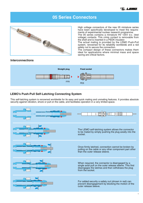
05 Series Connectors
High voltage connectors of the new 05 miniature series
have been specifically developed to meet the require-
ments of experimental nuclear research programme.
The 05 series contains a miniature HV 12kV d.c. (test
voltage) contacts. This crimp contact is removable from
the shell and is inserted in a PEEK insulator.
The actual mating is provided by the LEMO Push-Pull
system, renowned for its reliability worldwide and a red
safety nut to secure the connection.
The compact design of these connectors makes them
ideal for applications where minimal mass and space
saving are critical factors.
Interconnections
Straight plug Fixed socket
FFR
PES
LEMO’s Push-Pull Self-Latching Connecting System
This self-latching system is renowned worldwide for its easy and quick mating and unmating features. It provides absolute
security against vibration, shock or pull on the cable, and facilitates operation in a very limited space.
The LEMO self-latching system allows the connector
to be mated by simply pushing the plug axially into the
socket.
Once firmly latched, connection cannot be broken by
pulling on the cable or any other component part other
than the outer release sleeve.
When required, the connector is disengaged by a
single axial pull on the outer release sleeve. This first
disengages the latches and then withdraws the plug
from the socket.
For added security a safety nut (shown in red) can
prevent disengagement by blocking the motion of the
outer release sleeve.
1
Page4
® ®
Part Section Showing Internal Components
Connector
Straight plug
Fixed socket
7 2 1 5 6 3 4 8 6 5 1 3 2 4 7 1 outer shell
1 shell 2 latch sleeve
2 crimp back end 3 safety nut
3 hexagonal nut 4 crimp back end
4 conical nut 5 insulator
5 insulator 6 HV male contact
6 HV female contact 7 crimp ferrule
7 crimp ferrule 8 earthing crown
HV Contact
2 1 4 1 2
Male contact 3 3 Female contact
1 male contact 1 female contact
2 insulator 2 insulator
3 clips 3 clips
4 sealing gland
Technical characteristics
Mechanical and climatical Electrical characteristics
Characteristic Value Standard Characteristic Value Standard
Contact retention force 40 N IEC 60512-8 test 15a Test voltage d.c.1) 12 kV (1 min.) IEC 60512-2 test 4a
Working temperature -20 °C to +125°C Rated current 4 A IEC 60512-3 test 5a
Mechanical life > 200 cycles IEC 60512-5 test 9a Contact resistance ≤ 8 mΩ IEC 60512-2 test 2a
Climatic class 20/125/21 IEC 60068-1 Screen resistance ≤150 mΩ IEC 60512-2 test 2f
Radiation resistance > 106 Gy Insulation resistance ≥ 1012 Ω IEC 60512-2 test 3a
Note:
1) specific assembly instructions shall be respected. (see page 6 and 7)
Materials and Treatment – Connector Contact
Surface treatment Surface treatment
Component Material (standard) (µm) Component Material (standard) (µm)
Ni Cu Ni Au
Outershell + crimpend Aluminium (AA 6012) 5 Male contact Brass (UNS C38500) 0.5 3 1.0
Safety nut Aluminium (AA 6012) Anodized red Female contact Bronze (UNS C54400) 0.5 3 1.5
Earthing crown Aluminium special 5 Contact clips Cu-Be (QQ-C-530) –
Latch sleeve Aluminium special 5 Insulator PEEK –
Hex and conical nut Aluminium (AA 6012) Anodized natural Sealing gland Silicone PVMQ –
Insulator PEEK –
Crimp ferrule Aluminium (AA 6012) 5
2
Page5
® ®
Models
FFR Straight plug for cable crimping,
with safety nut
Part Number Cablegroup
42 FFR.05.403.LLAE141 1
FFR.05.403.LLAE142 2
29.8
PES Fixed socket, with two nuts, for cable crimping
Part Number Cablegroup
42
S 5.7 S 8 2.5 PES.05.403.LLLE141 1
PES.05.403.LLLE142 2
8.5 max. S 7
Recommanded high voltage cables
Construction and dimensions
Cable group Manufacturer CERN Type Conductor Dielectric Screen SheathPart Number Corona
Constr. Mat. ø Mat. ø Mat. Mat. ø screen
7x0.17 CuSn 0.51 PE solid 1.5 CuSn Polyo-1 ABBNK - 45/94 HTC 50-1-1 16x4x0.1 lefine 3.3 yes
HABIA Drain 2x0.12 HFI 150 mini coax
31789-004-001 Mono Cu 0.16 HFI150 0.5 + HFI150 1.15 noAlu polyester
3
M6.5x0.6
ø 8.5 ø 6
ø 9.2
Page6
® ®
Accessories
FFA-ERA High Voltage Contacts
Contact Part Number Cable L
Male contact Female contact group (mm)
male FFA.05.403.ZLA1 ERA.05.403.ZLL1 1 4
L FFA.05.403.ZLA2 ERA.05.403.ZLL2 2 6
female
GMA Heatshrink tube
Shall be ordered separately
Supplier
Part number Cable øD LL group Name Product reference (mm) (mm)
GMA.30.010.ST 1+2 RAYCHEM® RNF 3000 3/1 3.0 13
GMA.15.010.ST 2 RAYCHEM® RNF 3000 1.5/0.5 1.5 9
Note: for cable group 2, the two heatshrink tubes are necessary
● Material: Polyolefin transparent
FFS Crimp ferrule
10
ø 4.1
Model 1
Part number Cablegroup Model
FFS.05.160.PM 1 1
10 FFS.05.161.PM 2 2
ø 1.4
Model 2
● Material: Aluminium alloy (AA6012) nickel plated
GEC Conical nut
7
M 6.5 x 0.6 2.5
Part number
GEC.05.241.PT
● Material: Aluminium alloy (AA 6012) natural anodized.
GEA Hexagonal nuts
8
M 6.5 x 0.6 2
Part number
GEA.05.241.PT
● Material: Aluminium alloy (AA 6012) natural anodized.
4
9.2 ø 8.5
ø D min.
Page7
® ®
Tooling
37 DCH Spanner for conical nut
Part Number
DCH.91.113.9TN
ø 11
● Material: Blackened steel.
DCF Extraction tools for HV contacts
Part Number
DCF.91.133.5LT
Automatic model
DPH Crimping tool with die and positioner
Part Number Applications Cablegroup Marking on die
DPH.99.005.2K shield 1-2 DPH.91.005.2K
DPH.99.060.11K centre contact 1 DPH.91.001.16K
DPH.99.065.11K centre contact 2 DPK.91.001.16K
DPN Dies and positioner
Part Number Applications Cablegroup Marking on die
DPN.99.005.2K shield 1-2 DPH.91.005.2K
DPN.99.060.11K centre contact 1 DPH.91.001.16K
DPN.99.065.11K centre contact 2 DPK.91.001.16K
● Dies material: Blackened steel
Panel cut-out
10 min.
+ 0.1
5.8 0
Recommended mounting nut torque: 0.8 Nm.
5
ø 6.6 + 0.1 0
39.7
Page8
® ®
Termination Instructions Cable Group 1
5 3 4
FFR
1
5 3 4
PES
1. Strip the cable according to the given dimensions,
remove carefully the cable corona screen, making sure
9 ±0.2
3 ±0.2 that the cable dielectric is not damaged. Remove also
±0.2 the aluminium foil and the textile tape. 3.5
Clean the dielectric with isopropylic alcool.
Dimensions in mm.
Apply laquer 2. Place the crimp ferrule ➀ on the cable. Widen comple-3 4 1 tely the shield braid and fold it back over the jacket.
Introduce the cable center conductor into the HV
contact ➃ until the contact end rests against the dielec-
Crimp tric and the conductor is visible through the contact ins-
3 4 A 1 pection hole. Crimp with the LEMO crimping tool
DPH.99.060.11K. Cover the crimp section of the
contact and the Peek end of the HV contact with a layer
of insulating laquer. Let the laquer dry, approx.15 min.
Apply laquer Note: We recommand the laquer Urethan
ref: Cellpack n° 912110
3. Slide the heatshrink tube ➂ over the HV contact until it
4 3 rests against the contact insulator.
One end of the heatshrink tube shall be located at the
position A of the HV contact insulator. Shrink the tube.
Shrink
A
4 3
Shrink
4. Fully introduce the HV contact into the connector shell
5 1 ➄. Check that the contact is correctly located and
remains in position when given a gentle pull. Place the
cable shield braid strand over the shell crimp back end,
cut the length of braid in excess.
5 1
5. Slide the crimp ferrule over the cable shield until it
5 rests against the connector shell. Crimp with the
LEMO crimping tool DPH.99.005.2K.
Crimp
5
Crimp
6
Page9
® ®
Termination Instructions Cable Group 2
5 3 4 2
FFR
1
5 3 4 2
PES
14 ±0.2
1. Strip the cable according to the given dimensions, cut
10 ±0.2 the aluminium foil making sure that the dielectric is not
3 ±0.2 damaged. Do not damage the 2 drain wires.
Fold the drain wires back over the outer jacket and
slide over the small heatshrink tube ➁.
Clean the dielectric with isopropylic alcool.
2
Dimensions in mm.
2. Place the crimp ferrule ➀ introducing first the small dia-
meter on the cable. Introduce the cable center
3 4 Apply laquer 2 1 conductor and a part of the dielectric into the HV
contact ➃ until the conductor is fully visible through the
contact inspection hole. Crimp with the LEMO crimping
Crimp tool DPH.99.065.11K. Cover the crimp section of the
A B contact and a short length of the dielectric with a layer
of insulating laquer. Let the laquer dry, approx. 15 min.
Note: We recommand the laquer Urethan
3 4 2 1 ref: Cellpack n° 912110
Slide the heatskrink tube ➁ over the HV contact until it
rests against the contact insulator at the position B.
Apply laquer Shrink Shrink the tube. Cover the Peek end of the HV contact
and the first heatshrink tube with a layer of the insula-
ting laquer. Let the laquer dry, approx. 15 min.
4 3 1 3. Slide the heatshrink tube ➂ over the HV contact until itShrink rests against the contact insulator.
One end of the heatshrink tube shall be located at the
position A of the HV contact insulator. Shrink the tube.
A
4 3 1
Shrink
5 4. Fully introduce the HV contact into the connector shell
4 3 1 ➄. Check that the contact is correctly located and
remains in position when given a gentle pull. Place the 2
drain wire around the shell crimp back end.
5 A
4 3 1
5 5. Slide the crimp ferrule over the cable shield until it
rests against the connector shell. Crimp with the
LEMO crimping tool DPH.99.005.2K.
5 Crimp
Crimp
7
Page10
® ®
5G Series Connectors
High voltage cylindrical connectors of the new 5G series
have been specifically developed to meet the require-
ments of the “ATLAS” experimental nuclear research pro-
gramme at the CERN.
The 5G series contains 50 miniature HV 12kV d.c. (test
voltage) contacts. These crimp contacts are removable
from the shell and are inserted in a PEEK insulator. The
same HV contacts are used in the 05 series.
The actual mating is provided by the LEMO Push-Pull
system, renowned for its reliability worldwide and a red
safety nut to secure the connection.
Two keying alternative (code R or W) are available.
The compact design of these connectors makes them
ideal for applications where minimal mass and space
saving are critical factors.
Interconnections
Straight plug Fixed socket
FG
PH
LEMO’s Push-Pull Self-Latching Connecting System
This self-latching system is renowned worldwide for its easy and quick mating and unmating features. It provides absolute
security against vibration, shock or pull on the cable, and facilitates operation in a very limited space.
The LEMO self-latching system allows the connector
to be mated by simply pushing the plug axially into the
socket.
Once firmly latched, connection cannot be broken by
pulling on the cable or any other component part other
than the outer release sleeve.
When required, the connector is disengaged by a
single axial pull on the outer release sleeve. This first
disengages the latches and then withdraws the plug
from the socket.
For added security a safety nut (shown in red) can
prevent disengagement by blocking the motion of the
outer release sleeve.
8
DANGER
DANGER
DANGER
DANGER
Page11
® ®
Part Section Showing Internal Components
Connector
7 8 4 1 2 3 5 6 10 9 8 2 7 1 3 4 6 5
Fixed socket Straight plug
1 outer shell 6 conical nut 1 outer shell 5 adapter w. cable collet
2 earthing crown 7 adapter w. cable collet 2 latch sleeve 6 keyed mid-piece
3 retaining ring 8 keyed mid-piece 3 safety nut 7 insulator
4 clamp collet nut 9 insulator 4 clamp collet nut 8 HV female contact
5 round nut 10 HV male contact
HV Contact
2 3 1 4 1 2Male contact 3 Female contact
1 male contact 1 female contact
2 insulator 2 insulator
3 clips 3 clips
4 sealing gland
Technical characteristics
Mechanical and climatical Electrical characteristics
Characteristic Value Standard Characteristic Value Standard
Contact retention force 40 N IEC 60512-8 test 15a Test voltage d.c.1) 12 kV (1 min.) IEC 60512-2 test 4a
Working temperature -20 °C to +125°C Rated current 4 A IEC 60512-3 test 5a
Mechanical life > 100 cycles IEC 60512-5 test 9a Contact resistance ≤ 8 mΩ IEC 60512-2 test 2a
Climatic class 20/125/21 IEC 60068-1 Screen resistance ≤150 mΩ IEC 60512-2 test 2f
Radiation resistance >106 Gy Insulation resistance ≥ 1012 Ω IEC 60512-2 test 3a
Note: 1) specific assembly instructions shall be respected.
Materials and Treatment – Connector Contact
Surface treatment Surface treatment
Component Material (standard) (µm) Component Material (standard) (µm)
Ni Cu Ni Au
Outershell + collet nut Aluminium (AA 6012) Anodized natural Male contact Brass (UNS C38500) 0.5 3 1.0
Safety nut Aluminium (AA 6012) Anodized red Female contact Bronze (UNS C54400) 0.5 3 1.5
Earthing crown Aluminium special 5 Contact clips Cu-Be (QQ-C-530) –
Latch sleeve Aluminium special 5 Insulator PEEK –
Round and conical nut Aluminium (AA 6012) Anodized natural Sealing gland Silicone PVMQ –
Insulator PEEK –
Other metallic pieces Aluminium Anodized natural
9
DANGER
DANGER
Page12
® ®
Alignment key and polarized keying system
Angle HV contact type
β Ref. DotColour α β γ δ Plug Socket
●●R yellow 110° 105° 25° 35° male female
Front view of a socket ●●W red 95° 115° 20° 30° female male
Models
FG● Straight plug with keys (code R or W),
cable clamp-collet and safety nut
Part Number Cable Group
67
52 FGR.5G.450.LLAY5T1 1
FGR.5G.450.LLAY5T2 2
FGW.5G.450.LLLY5T1 1
FGW.5G.450.LLLY5T2 2
S 30 S 31
PH● Fixed socket with keys (code R or W),
cable clamp-collet, 2 nuts fixing
(back panel mounting)
S 37
~64.7 Part Number Cable Group
5 max. 5
PHR.5G.450.LLLY5T1 1
PHR.5G.450.LLLY5T2 2
PHW.5G.450.LLAY5T1 1
PHW.5G.450.LLAY5T2 2
S 30 S 31 S 33.5
Recommanded high voltage cables
Construction and dimensions
Cable group Manufacturer Type/Nb. of Conductor Dielectric Screen SheathPart Number CERN Type conductor Corona
Constr. Mat. ø Mat. ø Mat. Mat. ø screen
SILISOL
1 CEPMB -
CuSn
2 Multi/56 7x0.15 CuSn 0.45 PE 1.5 Silic 14.5 no56x0.12 mm + Alu
1 ABBNK - 45/94 HTC 50-1-1 Mono/1 7x0.17 CuSn 0.51 PE solid 1.5 CuSn Polyo- yes16x4x0.1 3.3lefine
Drain 2x0.1
2 HABIA HFI 150 mini Mono/1 Mono Cu 0.16 HFI150 0.5 + HFI150 1.15 no
31789-004-001 coax Alu polyester
10
α
ø 35
Cable ø Cable ø
14.0 min. 14.0 min.
16.5 max. 16.5 max.
δ
ø 41 ø 35
DANGER
DANGER
γ
Page13
® ®
Accessories
FFA-ERA HV Contacts
Contact Part Number Cable L
Male contact Female contact group (mm)
male FFA.05.403.ZLA1 ERA.05.403.ZLL1 1 4
L FFA.05.403.ZLA2 ERA.05.403.ZLL2 2 6
female
GMA Heatshrink tube
Shall be ordered separately
Supplier
L Part number Cable øD Lgroup Name Product reference (mm) (mm)
GMA.30.010.ST 1+2 RAYCHEM® RNF 3000 3/1 3.0 13
GMA.15.010.ST 2 RAYCHEM® RNF 3000 1.5/0.5 1.5 9
Note: for cable group 2, the two heatshrink tubes are necessary
● Material: Polyolefin transparent
GEC Conical nut
37
5
M 35 x 1
Part number
GEC.5G.240.PT
● Material: Aluminium alloy (AA6012) natural anodized
GEB Round nut
ø 40
M 35 x 1 8
Part number
GEB.5G.240.PT
● Material: Aluminium alloy (AA6012) natural anodized
FGG Extension piece
36
Part Number
FGG.5G.815.PN
Note: allows an extension of the plug or the socket to make cable strip-
ping and mounting easier when weight and size are not critical
● Material: Aluminium alloy (AA6012) natural anodized
11
ø 27.9
ø 41 ø D min.
ø 29
Page14
® ®
Tooling
90 DCH Spanner for conical nut
Part Number
DCH.91.418.0TN
ø 45
● Material: Blackened steel.
54 DCP Set of flat spanners for collet nuts and round nuts
31.1
30.1 3.5
Part Number
DCP.91.005.TN
● Material: Blackened steel.
DCF Extraction tools for HV contacts
Part Number
DCF.91.133.5LT
Automatic model
DPH Crimping tool with die and positioner
Part Number Applications Cablegroup Marking on die
DPH.99.005.2K shield 1-2 DPH.91.005.2K
DPH.99.060.11K centre contact 1 DPH.91.001.16K
DPH.99.065.11K centre contact 2 DPK.91.001.16K
Note: DPN Dies and positioner: See 05 series data sheet.
Panel cut-out
42 min.
+ 0.1
33.5 0 Recommended mounting nut torque: 7 Nm.
12
ø 35.2 + 0.1
0
160
81.5
Page15
® ®
Termination Instructions Cable Group 1 (multi HT cable)
7 5 3 4
6 1
FG•
7 5 3 4
PH•
2
500 1. Strip the cable according to the given dimensions.
A 500 mm length is necessary to give enough flexibi-
24 lity to the cable.
3.5 ±0.2 Remove first the outer jacket and the screen then the
dielectric of each individual high-voltage conductor,
making sure that the cable dielectric is not damaged.
Dimensions in mm.
2. Slide 2 pieces of 55mm heat-shrink tubing, (not sup-
plied) of the correct size, the clamp collet nut ➀ and
55 1 55 the adapter with cable collet ➁ on the cable.
2
Apply laquer 3. For each individual high-voltage conductor install a
3 4 HV contact as follow:Crimp
3.1 Introduce the cable center conductor into the HV
contact ➃ until the conductor end rests against the
dielectric and the conductor is visible through the
contact inspection hole. Crimp with the LEMO crim-
ping tool DPH.99.060.11K. Cover the crimp section of
A the contact and the Peek end of the HV contact with
3 4 Crimp a layer of insulating laquer. Let the laquer dry,
approx. 15 min.
Note: We recommand the laquer Urethan
ref: Cellpack n° 912110
Apply laquer
3.2 Slide the heatshrink tube ➂ over the HV contact until
it rests against the contact insulator.
4 3 Shrink One end of the heatshrink tube shall be located at the
position A of the HV contact insulator. Shrink the
tube.
A
4 3 Shrink
13
Page16
® ®
5 4. Fully introduce the HV contacts into the insulator ➄.
– The short insulator shall be fitted with the female
HV contacts.
– The long insulator shall be fitted with the male
HV contacts.
5 Check that the contacts are correctly located and
remains in position when given a gentle pull.
solder ground wire L = 130 mm 5. Install a ground wire (not supplied) as follow:
5.1 Wrap a tin copper wire 0.5 mm2 over a 6 mm length
of the cable screen and hold the ground wire as
shown. Then solder.
Solder an earthing washer with a 3.5 mm hole on the
other side.
6
solder ground wire L = 130 mm
6
Shrink Shrink 5.2 Cover the end of the cable screen with the first heat-
25 shrink tube and the end of the cable jacket with the
second heat-shrink tube, then shrink.
55 55
Shrink Shrink
25
55 55
6 6. Push the adapter with cable collet ➁ forward over the
cable until the insulator locate into the groove on the
adapter.
Then fit the keyed mid-piece ➅ onto the insulator,
make sure that the key of the insulator is correctly
located into the key of the mid-piece.
2
6
2
7 1 7. Next slide the connector shell ➆ over the insulator
assembly making sure that the key on the keyed mid
piece goes into the key-way (under the color
point/inside the shell).
– Note that the HV contact type shall be respected
depending upon the keying code as indicated on
7 1 page 10.Screw the collet nut ➀ and tighten to the maximum
torque value of 4 Nm.
Tight the two screws of the adapter and in between
on an appropriate manner the washer of the ground
wire.
14
Page17
REDEL Kft
Elektronika
K and S Series Connectors
High voltage rectangular connectors of the new K and S
series have been specially developed to meet the
requirements of the “ATLAS” experimental nuclear
research programme at the CERN.
The K series contains 22 miniature HV contacts (12kV
d.c. test voltage).
The S series contains 51 miniature HV contacts (12kV
d.c. test voltage). These crimp contacts are removable
from the shell and are inserted in a PEEK insulator. The
mating is assured by guide pins and sleeves. Two red
sliding tabs secure the connection by locking a pair of
levers to a bracket mounted on the housing. The rectan-
gular design of these connectors makes them ideal for
applications where space saving is critical; for example
on narrow panels.
INTERCONNECTION
Straight socket Fixed socket Straight plug
KR/SR KL/SL KA/SA
SELF-1LATCHING CONNECTING SYSTEM 3
1 3
1
The REDEL Self-Latching connecting system allows the connectors The connectors are disengaged by pressing down on the latch
to be mated by simply pushing the plug axially into the socket levers and then withdrawing the plug from the socket
1
2 4
Once latched, connection cannot be broken by pulling on the For added security two red tabs can be slid forward, locking the
cable o2r any other component part latch leve4rs in place.
2
ALIGNMENT KEY
Code G Code A
2
KRG/SRG KLG/SLG KAG/SAG KRA/SRA KLA/SLA KAA/SAA
Modification 08.05 15
REDEL REDEL
KLG.H22 KLG.H22
REDEL
KAG.H22
REDEL
KLG.H22
REDEL
KAG.H22
REDEL
KAG.H22
REDEL
KLG.H22
REDEL REDEL
KLG.H22 KLG.H22
REDEL REDEL
REDEL KAG.H22 KAG.H22
KLA.H22
REDEL
KAG.H22
REDEL
KAA.H22
REDEL
KRA.H22
REDEL
KRG.H22
REDEL
KRG.H22
Page18
REDEL Kft
PART SECTION SHOWING INTERNAL COMPONENTS
Connector
Rectangular plug
7 6 8 1 5 2 3 4 7 6 5 3 2 8 4 1 9 11 10
Rectangular socket 1 outer shell
2 latch lever
1 outer shell 3 locking clip
2 insulator 4 security tab
3 HV male contact 5 insulator
4 male guide pin 6 HV female contact
5 threaded insert 7 female guide pin
6 cable clamp 8 threaded insert
7 earthing insert 9 cable clamp
8 earthing tag 10 earthing insert
11 earthing tag
HV Contact
2 3 1 4 1 3 2Male contact Female contact
1 male contact 1 female contact
2 insulator 2 insulator
3 clips 3 clips
4 sealing gland
TECHNICAL CHARACTERISTICS
Mechanical and climatical Electrical characteristics
Characteristic Value Standard Characteristic Value Standard
Contact retention force 40 N IEC 60512-8 test 15a Test voltage d.c.1) 9/12 kV (1 min.) IEC 60512-2 test 4a
Working temperature -20 °C to +125°C Rated current 4 A IEC 60512-3 test 5a
Mechanical life > 100 cycles IEC 60512-5 test 9a Contact resistance ≤ 8 mΩ IEC 60512-2 test 2a
Climatic class 20/125/21 IEC 60068-1 Screen resistance ≤150 mΩ IEC 60512-2 test 2f
Radiation resistance > 106 Gy Insulation resistance ≥ 1012 Ω IEC 60512-2 test 3a
Note: 1) specific assembly instructions shall be respected.
9 kV dc apply to the pair KA●/KL● and SA●/SL●.
12 kV dc apply to the pair KA●/KR● and SA●/SR●.
Materials and Treatment – Connector Contact
Surface treatment Surface treatment
Component Material (standard) (µm) Component Material (standard) (µm)
Ni Cu Ni Au
Outershell Aluminium 5 Male contact Brass (UNS C38500) 0.5 3 1.0
Latching mechanism Bronze 5 Female contact Bronze (UNS C54400) 0.5 3 1.5
Insulator PEEK – Contact clips Cu-Be (QQ-C-530) –
cable clamp PSU – Insulator PEEK –
Other met. pieces Stainless Steel – Sealing gland Silicone PVMQ –
Other plastic pieces PSU –
16 Modification 08.05
KAG
.H22
Page19
REDEL Kft
MODELS K series (22 contacts)
KA● Straight plug with key (code G or A)
and cable collet
Part Number Cable Group ContactType Marking68.5
KAG.H22.LLZBG female black
no contact
KAA.H22.LLZBG male red
KAG.H22.LLLB1G female black
1
KAA.H22.LLAB1G male red
KAG.H22.LLLB2G female black
2
KAA.H22.LLAB2G male red
46.6
KL● Fixed socket with key (code G or A),
two screw fixing
23 Part Number Cable Group ContactType Marking
KLG.H22.LLZG male black
no contact
KLA.H22.LLZG female red
KLG.H22.LLA1G male black
1
KLA.H22.LLL1G female red
1 17
7 12 KLG.H22.LLA2G male black
2
KLA.H22.LLL2G female red
11 16
6 22
36
KR● Straight socket with key (code G or A)
and cable collet
69.6
Part Number Cable Group ContactType Marking
KRG.H22.LLZBG male black
no contact
KRA.H22.LLZBG female red
KRG.H22.LLAB1G male black
1
KRA.H22.LLLB1G female red
1 17
7 12 KRG.H22.LLAB2G male black
2
KRA.H22.LLLB2G female red
11 16
6 22
Modification 08.05 17
Cable ø
6 mm min. Cable ø
9.5 mm max. 6 mm min.
9.5 mm max.
REDEL
KLG.H22
33.4 16
37.4
33.4 16
43.4 16
37.4
17 1
12 7
16 11
22 6
REDEL REDEL
KRG.H22
KAG.H22
Page20
REDEL Kft
MODELS S series (51 contacts)
SA● Straight plug with key (code G or A)
and cable collet
Part Number Cable Group ContactType Marking
75.5
SAG.H51.LLZBG female black
no contact
SAA.H51.LLZBG male red
SAG.H51.LLLB1G female black
1
SAA.H51.LLAB1G male red
SAG.H51.LLLB2G female black
2
SAA.H51.LLAB2G male red
53.6
SL● Fixed socket with key (code G or A),
two screw fixing
Part Number Cable Group ContactType Marking
23
SLG.H51.LLZG male black
no contact
SLA.H51.LLZG female red
SLG.H51.LLA1G male black
1
SLA.H51.LLL1G female red
1 41
12 31
22 SLG.H51.LLA2G male black
2
SLA.H51.LLL2G female red
30
21 40
11 51
36
SR● Straight socket with key (code G or A)
and cable collet
76.6 Part Number Cable Group ContactType Marking
SRG.H51.LLZBG male black
no contact
SRA.H51.LLZBG female red
SRG.H51.LLAB1G male black
1
1 41
12 31 SRA.H51.LLLB1G female red
22
SRG.H51.LLAB2G male black
2
SRA.H51.LLLB2G female red
30
21 40
11 51
18 Modification 08.05
Cable ø
7.5 mm min. Cable ø
12.5 mm max. 7.5 mm min.
12.5 mm max.
REDEL
SLG.H51
43 19.6
43 19.6 47
53 19.6
47
41 1
31 12
22
30
40 21
51 11
REDEL REDEL
SRG.H51
SAG.H51