


COAXIAL, TRIAXIAL,MULTI & MIXED CONNECTORS
※レモコネクタはモジュール方式のため、共通部品を組み合せることにより様々なコネクタに変えることができます。このため、カタログに掲載されている写真や図は、色、形状などが実物とは微妙に異なっている場合や、写真撮影の方向が一定していない場合がございます。ご注意いただきますようお願いいたします。
このカタログについて
| ドキュメント名 | 各種同軸複合コネクタ |
|---|---|
| ドキュメント種別 | 製品カタログ |
| ファイルサイズ | 3.2Mb |
| 登録カテゴリ | |
| 取り扱い企業 | レモジャパン株式会社 (この企業の取り扱いカタログ一覧) |
この企業の関連カタログ


このカタログの内容
Page1
COAXIAL, TRIAXIAL, SHORT FORM
MULTI & MIXED CONNECTORS CATALOGUE
Page2
® ®
Precision modular connectors to suit your application
Since its creation in Switzerland in 1946 the LEMO Group has been recognized as a global leader of circular Push-Pull con-
nectors and connector solutions. Today LEMO and its affiliated companies, REDEL and COELVER, are active in more than
80 countries with the help of over 40 subsidiaries and distributors.
Over 75’000 connectors
The modular design of the LEMO range provides over 75’000 connectors from miniature ø 3 mm to ø 50 mm, capable of han-
dling cable diameters up to 30 mm and for up to 114 contacts.
This vast portfolio enables you to select the ideal connector configuration to suit almost any specific requirement in most mar-
kets, including medical devices, test and measurement instruments, machinery, audio video broadcast, telecommunications
and military.
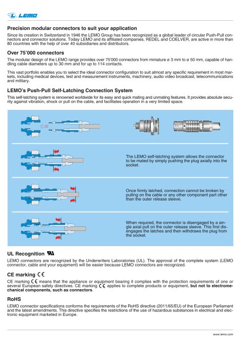
LEMO’s Push-Pull Self-Latching Connection System
This self-latching system is renowned worldwide for its easy and quick mating and unmating features. It provides absolute secu-
rity against vibration, shock or pull on the cable, and facilitates operation in a very limited space.
The LEMO self-latching system allows the connector
to be mated by simply pushing the plug axially into the
socket.
Once firmly latched, connection cannot be broken by
pulling on the cable or any other component part other
than the outer release sleeve.
When required, the connector is disengaged by a sin-
gle axial pull on the outer release sleeve. This first dis-
engages the latches and then withdraws the plug from
the socket.
UL Recognition
LEMO connectors are recognized by the Underwriters Laboratories (UL). The approval of the complete system (LEMO
connector, cable and your equipment) will be easier because LEMO connectors are recognized.
CE marking
CE marking means that the appliance or equipment bearing it complies with the protection requirements of one or
several European safety directives. CE marking applies to complete products or equipment, but not to electrome-
chanical components, such as connectors.
RoHS
LEMO connector specifications conforms the requirements of the RoHS directive (2011/65/EU) of the European Parliament
and the latest amendments. This directive specifies the restrictions of the use of hazardous substances in electrical and elec-
tronic equipment marketed in Europe.
www.lemo.com
Page3
® ®
Introduction
This catalogue gives the complete description of LEMO connectors with coaxial, triaxial and mixed contacts.
Mixed contacts include coaxial and low voltage contact configurations, as well as multi-coaxial contact configurations.
The LEMO manufacturing programme has been extended to almost 40 series divided into 7 product families with specific
mating and environmental characteristics. Each series includes a wide variety of plug, socket and coupler models, avail-
able in contact configurations adapted to all round cables. The catalogue includes the B, K, S and E Series of the LEMO
product range. In addition the 00 Series (triaxial) connector is also represented.
Watertight and vacuumtight models are also available. Since LEMO connectors are perfectly screened and designed to guar-
antee very low resistance to shell electrical continuity, they are particularly adapted to applications where electromagnetic
compatibility (EMC) is important.
Material and treatment
Surface treatment (µm)
Component Material (Standard) chrome nickel gold black chr. Notes
Cu Ni Cr Cu Ni Cu Ni Au Ni Cr
Brass (UNS C 38500) 0.5 3 0.3 0.5 3 0.5 3 0.5 1 2
Stainless steel (AISI 303, 304 or 316L) without treatment
Aluminium alloy (AA 6262A or AA 6023) anodized
Outer shell, ® ® 1)
collet nut, conical nut POM (Delrin or Ertacetal ), Polyoxymethylene, black –
or notched nut and oversized collet PEEK, Polyether ethercetone, beige – 2)
PSU (Udel®), Polysulfone, grey or white – 3)
PPSU (Radel®), Polyphenylsulfone, cream – 3)
PPS (Ryton®), Polyphenilene sulfide, brown – 4)
Bronze (UNS C 54400) or special brass – – – 0.5 3 0.5 3 1.0 – – 5)
Earthing crown Beryllium Copper (UNS C 17300) – – – 0.5 3 0.5 3 1.0 – – 6)
Stainless steel (AISI 416 or 316L) without treatment 7)
Special brass 0.5 3 0.3 0.5 3 0.5 3 0.5 – –
Latch sleeve
Stainless steel (AISI 416 or 316L) without treatment 7)
Locking washer Bronze (UNS C 52100)
– – – 0.5 3 0.5 3 0.5 – –
Brass (UNS C 38500)
Hexagonal or round nut Stainless steel (AISI 303, 304 or 316L) without treatment 8)
Aluminium alloy (AA 6262A or AA 6023) anodized natural 8)
Brass (UNS C 38500) – – – 0.5 3 0.5 3 0.5 – –
Other metallic components
Stainless steel (AISI 303, 304 or 316L) without treatment
O-ring and gaskets Silicone MQ/MVQ or FPM/FKM (Viton®) – 9)
Sealing resin Epoxy (Araldite® or Stycast®) –
Notes: 3) for the FGG, FGY and ENY models of the 2B to 4B series
standards for surface treatment are as follows: 4) for 00 triaxial series (elbow sockets for printed circuits)
– chrome-plated: SAE AMS 2460 5) gold-plating for unipole types
– nickel-plated: SAE AMS QQ N 290, or MIL DTL 32119 6) used in 00 series free and fixed sockets
– gold-plated: ISO 27874 7) AISI 416 steel is used with shells made of AISI 303 or 304
– black chrome: MIL-C-14538C with a minimum of 10 µm of lacquer 8) delivered with free and fixed sockets with aluminium alloy or stainless
protection steel shell
1) for FFP, PCP and ERN models of the 0S to 3S series 9) FPM/FKM (Viton®) o-ring and gaskets are installed upon special
2) for FFP, PCP and ERN models of the 0S to 3S series, FGG and ENG request. However standard for vacuumtight models.
models of the 0B, 1B, 3B and 4B series, FFA and FFC models of the
00 triaxial series
www.lemo.com 1
Page4
® ®
B Series
B series connectors provide the following main features:
– security of the Push-Pull self-latching system – up to 10 coaxial contacts
– coaxial, triaxial and mixed contact configurations – solder or crimp contacts
– plastic models made of PSU or PPSU – high packing density for space savings
– multiple key options to avoid cross mating – 360° screening for full EMC shielding
of similar connectors («G» key standard).
Metal housing models
Fixed plugs Straight plugs Fixed sockets Free sockets
FWG FGG EGG EJG PHG
FAG FGG ENG EEG PHG
Elbow plugs
FFG EKG ECG PNG
FHG Fixed sockets
FNG EHG
PKG
FKG FEG
PFG
FDG
PEG
FIG
Plastic housing models
Straight plugs Fixed sockets
FGG FGG ENG
FGY FGY ENY
Model Description
ECG Fixed socket with two nuts, key (G) or keys FEG Straight plug, key (G) or keys (A…L), cable FKG Elbow (90°) plug for remote handling,
(A…L and R) (back panel mounting) collet, front seal and nut for fitting a bend key (G) or keys (A…L), special alignment
EEG Fixed socket, nut fixing, key (G) or keys relief (IP 54 protection index when mated) mark, knurled handling surface,
(A…L and R) (back panel mounting) FFG Straight plug, non-latching, key (G) cable collet
EGG Fixed socket, nut fixing, key (G) or keys (A…L), cable collet FNG Straight plug, key (G) or keys (A…L and R),
or keys (A…L and R) FGG Straight plug, key (G) or keys (A…L and R), cable collet and lanyard release
EHG Fixed socket, nut fixing, key (G) or keys cable collet FWG Fixed plug, nut fixing, key (G) or keys (A…L)
(A…L and R), and protruding shell FGG Straight plug, key (G) or keys (A…L), PEG Fixed socket, nut fixing, key (G) or keys
EJG Fixed socket, press or adhesive fit, cable collet and nut for fitting a bend relief (A…L), cable collet (back panel mounting)
key (G) or keys (A…L) FGG Straight plug, key (G or J), cable collet, PFG Fixed socket, with two nuts, key (G)
EKG Fixed socket, nut fixing, key (G) or keys PEEK outer shell or keys (A…L and R), cable collet
(A…L and R), special alignment mark FGG Straight plug, key (G or J), cable collet, (back panel mounting)
on the front PEEK outer shell, nut for fitting a bend relief PHG Free socket, key (G) or keys (A…L and R),
ENG Fixed socket with earthing tag, nut fixing, FGY Straight plug, keys (Y), cable collet cable collet
key (G) or keys (A…L) and PSU or PPSU outer shell PHG Free socket, key (G) or keys (A…L),
ENG Fixed socket with earthing tag, nut fixing, FGY Straight plug, keys (Y), cable collet cable collet and nut for fitting a bend relief
key (G or J), PEEK outer shell and PSU or PPSU outer shell and nut PKG Fixed socket, nut fixing, key (G)
ENY Fixed socket with earthing tag, nut fixing, for fitting a bend relief or keys (A…L and R), cable collet
keys (Y), PSU or PPSU outer shell FHG Elbow (90°) plug, key (G) or keys PNG Free socket, nut fixing, key (G) or keys
FAG Fixed plug, non-latching, nut fixing, (A…L and R), cable collet (A…L and R), cable collet with lanyard
key (G) or keys (A…L and R) FIG Straight plug for remote handling, key (G) release
FDG Straight plug, long version, or keys (A…L and R), special alignment
key (G) or keys (A…L), cable collet mark, knurled handling surface, cable collet
2 www.lemo.com
Page5
® ®
Part Numbering System
Plug FG G . 3B . 844 . C L A D 11 1
Free socket PH G . 3B . 844 . C L L D 11 1
Cable group
Variant: Z = collet nut for bend relief
Cable ø max. 1)
Collet type: D or M
Fixed socket EG G . 3B . 844 . C L L 1
Cable group
Contact type:
A = male solder
Model C = male crimpL = female solder
M = female crimp
Alignment key: G
Insulator: L = PEEK
Series
Housing:
Insert configuration: C = brass chrome-plated
multi coax, coax + LV P = PSU
Part Number Example
Straight plug with cable collet:
FGG.3B.844.CLAD111 = straight plug with key (G) and cable collet, 3B series, mixed coax & low voltage type (1 coax and
4 low voltage contacts), outer shell in chrome-plated brass, PEEK insulator, male solder contacts, D type collet for up to
11 mm diameter cable. Cable group 1.
Free socket:
PHG.3B.844.CLLD111 = free socket with key (G) and cable collet, 3B series, mixed coax & low voltage type (1 coax and
4 low voltage contacts), outer shell in chrome-plated brass, PEEK insulator, female solder contacts, D type collet for up to
11 mm diameter cable. Cable group 1.
Fixed socket:
EGG.3B.844.CLL1= fixed socket, nut fixing, with key (G), 3B series, mixed coax & low voltage type (1 coax and 4 low volt-
age contacts), outer shell in chrome plated brass, PEEK insulator, female solder contacts. Cable group 1.
Note: 1) see unipole-multipole catalogue (p. 52).
Part Section Showing Internal Components (mixed coax + LV)
Fixed socket Straight plug
8 7 6 2 3 4 5 1 1 8 6 5 4 2 7 3
1 outer shell 1 outer shell
2 earthing crown 2 latch sleeve
3 retaining ring 3 collet nut
4 hexagonal nut 4 split insert carrier
5 locking washer 5 insulator
6 insulator 6 male contact
7 female contact 7 collet
8 female coaxial contact 8 male coaxial contact
www.lemo.com 3
Page6
® ®
K Series
K series connectors have been specifically designed for outdoor applications.
They include an inner sleeve and two seals to prevent penetration of solids or liquids into the housing formed by the plug,
free socket or fixed socket. All models of this series are watertight when mated to give a protection index of IP68 as per
IEC 60529 standard (in mated condition) when correctly assembled to an appropriate cable (IP66 otherwise).
K series connectors have the same insulators as the B series and have the following main features:
– security of the Push-Pull latching system – watertight connection (IP 68/IP 66)
– coaxial, triaxial and mixed contact configurations – up to 10 coaxial contacts
– solder or crimp contacts – 360° screening for full EMC shielding
– multiple key options to avoid cross mating – high packing density for space savings
of similar connectors («G» key standard) – rugged housing for extreme working conditions.
Models
Fixed plugs Straight plugs Fixed sockets Free sockets Fixed sockets
FGG PHG
FXG EGG PKG
FAG FGG PHG
EEG PEG
Elbow plug
FGG PHG
FHG EBG
EDG
EHG
Model Description
EBG Fixed socket with square flange, FGG Straight plug, key (G) or keys PHG Free socket, key (G) or keys (A to F, L and
key (G) or keys (A to F, L and R) (A to F, L and R), cable collet R), cable collet
and screw fixing FGG Straight plug, key (G) or keys (A to F, L PHG Free socket, key (G) or keys (A to F, L and
EDG Fixed socket with square flange, key (G) and R), cable collet and oversize cable R), cable collet and oversize cable collet
or keys (A to F, L and R), protruding shell collet PHG Free socket, key (G) or keys (A to F, L and
and earthing tag, screw fixing FGG Straight plug, key (G) or keys (A to F, L R), cable collet and nut for fitting a bend
EEG Fixed socket, nut fixing, key (G) and R), cable collet and nut for fitting a relief
or keys (A to F, L and R) bend relief PKG Fixed socket, nut fixing, key (G)
(back panel mounting) FHG Elbow (90°) plug, key (G) or keys (A to F, L or keys (A to F, L and R), cable collet
EGG Fixed socket, nut fixing, key (G) and R), cable collet
or keys (A to F, L and R) FXG Fixed plug with round flange, key (G)
EHG Fixed socket, nut fixing, key (G) or keys (A to F, L and R) and screw fixing
or keys (A to F and L), protruding shell PEG Fixed socket, nut fixing, key (G)
FAG Fixed plug, nut fixing, non-latching, or keys (A to F, L and R), cable collet
key (G) or keys (A to F, L and R) (back panel mounting)
4 www.lemo.com
Page7
® ®
Part Numbering System
Plug FG G . 3K . 844 . C L A C 11 3
Free socket PH G . 3K . 844 . C L L C 11 3
Cable group
Variant: Z = collet nut for bend relief
Cable ø max. 1)
Collet type: C or K
Fixed socket EG G . 3K . 844 . C L L 1
Cable group
Contact type:
Model A = male solder
C = male crimp
L = female solder
Alignment key: G M = female crimp
Series Insulator: L = PEEK
Insert configuration: Housing:
multi coax, coax + LV C = brass chrome-plated
Part Number Example
Straight plug with cable collet:
FGG.3K.844.CLAC113 = straight plug with key (G) and cable collet, 3K series, mixed coax & low voltage type (1 coax and
4 low voltage contacts), outer shell in chrome-plated brass, PEEK insulator, male solder contacts, C type collet for 10.5 mm
diameter cable. Cable group 3.
Free socket:
PHG.3K.844.CLLC113 = free socket with key (G) and cable collet, 3K series, mixed coax & low voltage type (1 coax and
4 low voltage contacts), outer shell in chrome-plated brass, PEEK insulator, female solder contacts, C type collet for 10.5
mm diameter cable. Cable group 3.
Fixed socket:
EGG.3K.844.CLL1 = fixed socket, nut fixing, with key (G), 3K series, mixed coax & low voltage type (1 coax and 4 low volt-
age contacts), outer shell in chrome-plated brass, PEEK insulator, female solder contacts. Cable group 1.
Note: 1) see unipole-multipole catalogue (p. 53).
Part Section Showing Internal Components (mixed coax + LV)
Straight plug
Fixed socket 1 outer shell
2 latch sleeve
1 outer shell 8 5 2 3 4 7 1 6 13 8 2 3 7 6 4 1 9 11 12 10 5 3 inner shell
2 earthing crown 4 retaining ring
3 retaining ring 5 collet nut
4 hexagonal nut 6 split insert carrier
5 insulator 7 insulator
6 female contact 8 male contact
7 o-ring 9 earthing cone
8 female coaxial contact 10 collet
11 gasket
12 washer
13 male coaxial contact
www.lemo.com 5
Page8
® ®
Insert configuration (B and K series)
Mixed: multi coax, coax + LV
Coax Low voltage (LV)
Coax Contacts
type
1B 801 1 50 F 2 1 0.9 ● ● 0.85 1.20 10
1K
803 1 50 F 2 3 0.9 ● ● 0.75 1.05 10
2B 802 1 50 A1 1-2-3 2 0.9 ● ● 0.85 1.20 10
2K
804 1 50 A1 1-2-3 4 0.7 ● ● 0.75 1.05 7
806 1 50 A1 1-2-3 6 0.7 ● ● 0.75 1.05 7
810 1 50 C 1-2-3 10 0.7 ● ● 0.95 1.35 7
841 2 50 E 2 1 1.6 ● ● 1.90 2.70 17
232 2 50 G – – – – – – – –
243 3 50 E 2 – – – – – – –
3B 803 1 50 A0 6 3 0.9 ● – 1.10 1.55 8
3K
806 1 50 A1 1-2-3 6 0.7 ● ● 1.00 1.50 7
809 1 50 A1 1-2-3 9 0.7 ● ● 1.00 1.50 7
812 1 50 A1 1-2-3 12 0.9 ● ● 0.90 1.30 9
813 1 50 A1 1-2-3 13 0.7 ● ● 0.90 1.30 7
822 1 50 C 1-2-3 22 0.7 ● ● 0.70 1.00 5
844 2 50 C 1-2-3 4 0.9 ● ● 0.90 1.30 10
846 2 50 C 1-2-3 6 0.9 ● ● 0.90 1.30 10
850 2 50 C 1-2-3 10 0.7 ● ● 0.75 1.05 8
856 2 50 C 1-2-3 16 0.7 ● ● 0.70 1.00 7
242 2 50 C 1-2-3 – – – – – – –
B R
G 243 3 50 C 1-2-3 – – – – – – –
862 3 50 C 1-2-3 2 0.9 ● ● 1.10 1.60 9
● First choice alternative
● Special order alternative
6 www.lemo.com
ø A
Reference
Number of contacts
Impedance (Ω)
Type (see page 10)
Cable group
Number of contacts
ø A (mm)
Solder
Crimp
Test voltage
(kV rms)
Test voltage
(kV dc)
Rated current (A)
Page9
® ®
Mixed: multi coax, coax + LV
Coax Low voltage (LV)
Coax Contacts
type
4B 802 50 A 5-6
822 1 75 A 4 to 6 2 0.9 ● ● 1.00 1.40 124K
804 1 50 A 5-6824 75 A 4 to 6 4 0.9 ● ● 1.00 1.40 10
806 1 50 A 5-6826 75 A 4 to 6 6 0.9 ● ● 1.00 1.40 10
842 2 50 A1 1-2-3 2 0.9 ● ● 1.70 2.40 12
844 2 50 A1 1-2-3 4 0.9 ● ● 1.70 2.40 10
852 2 50 C 1-2-3 12 0.9 ● ● 0.90 1.30 8
856 2 50 C 1-2-3 16 0.9 ● ● 0.90 1.30 8
858 2 50 C 1-2-3 18 0.7 ● ● 0.80 1.10 7
866 3 50 C 1 6 0.7 ● ● 0.80 1.10 7
885 3 50 C 1-2-3 12 0.7 ● ● 0.80 1.10 8
244 4 50 C 1-2-3 – – – – – – –
879 4 50 C 1-2-3 9 0.7 ● ● 0.90 1.30 8
890 6 50 E 2 18 0.7 ● ● 0.90 1.30 5
894 6 50 E 2 22 0.7 ● ● 0.90 1.30 4
5B
5K
997 1) 1 75 A4 N/A 32 1.3 ● ● 1.20 1.70 8
840 1 50 A 5-6 40 0.9 ● ● 1.30 1.80 7
● First choice alternative ● Special order alternative Note: 1) only available in 5B series. Solution for triaxial cable fixing.
www.lemo.com 7
ø A
Reference
Number of contacts
Impedance (Ω)
Type (see page 10)
Cable group
Number of contacts
ø A (mm)
Solder
Crimp
Test voltage
(kV rms)
Test voltage
(kV dc)
Rated current (A)
Page10
® ®
Mixed: multi coax, coax + LV
Coax Low voltage (LV)
Coax Contacts
type
5B
5K 868 1 50 B 6 4 3.044 0.9 ● ● 0.80 1.15 356
850
870 2
50 B 6
75 B 3-5 10 0.9 ● ● 1.40 2.00 8
856 50 B 6
876 2 75 B 3-5 16 0.9 ● ● 1.40 2.00 7
857 2 50 B 6 2 2.0
● ● 1.40 2.00 30
877 75 B 3-5 15 0.9 ● ● 1.40 2.00 7
C1
864 2 75 B0 1-6 24 1.3 ● ● 0.90 1.30 8
C2
273 3 75 B1 5 – – – – – – –
274 4 75 B1 5 – – – – – – –
892 6 75 D 5-8-9 10 0.9 ● ● 0.70 1.00 7
260 7 75 D 5-8-9 – – – – – – –
240 10 50 C 1-2-3 – – – – – – –
● First choice alternative ● Special order alternative
8 www.lemo.com
ø A
Reference
Number of contacts
Impedance (Ω)
Type (see page 10)
Cable group
Number of contacts
ø A (mm)
Solder
Crimp
Test voltage
(kV rms)
Test voltage
(kV dc)
Rated current (A)
Page11
® ®
Mixed: coax + LV + HV, coax + LV + Fluidic, coax + LV + Fibre optic
Coax Low volt. High volt. Fibre optic Fluidic(LV) (HV) (FO) (FL)
Coax
2B
2K 932 1 50 2.0 C 1 21) 0.7 1 2) 0.7 – – – –
3B 934 1 50 2.0 C 1 4 0.9 1 0.9 – – – –
3K
970 1 50 2.0 C 1 10 0.7 – – – – 1 1.3
986 1 50 2.0 C 1 16 0.7 – – 1 F2 – –
Note: 1) Test voltage LV contact-shell 1.9 (kV rms). 2) Test voltage HV contact-shell 7.5 (kV rms). Total rated current for 2B.932 configuration 6 (A).
www.lemo.com 9
ø A
Reference
Number of contacts
Impedance (Ω)
Rated current (A)
Type (see page 10)
Cable group
Number of contacts
ø A (mm)
Number of contacts
ø A (mm)
Number of contacts
Type
Number of contacts
Inner tube ø (mm)
Page12
® ®
Coaxial contacts for B and K series
Sheath ø
F 1) 50 0.5 solder crimp 2 0.35 1.05 – 2.10 1.05+1.83f 0.8 2
1 0.60 1.90 2.5 3.00
A1 50 0.7 solder collet 2 0.60 1.90 1.7 2.10 1.01 0.9 5
3 0.60 1.90 2.2 2.60 +0.127f
1 0.50 0.58 1.65 3.00
C 1) 50 0.6 crimp crimp 2 0.28 0.35 1.05 – 2.35 1.04 1.6 2
3 0.28 0.35 1.65 3.00 +0.1f
E 1) 50 0.5 solder crimp 2 0.35 0.95 – 2.00 1.02+0.93f 0.8 2
50 1.6 solder collet 5 1.35 3.95 4.3 5.10 1.016 1.35 3.95 5.3 6.10 +0.146f 1.8 12
A
4 1.05 3.95 3.8 4.60
75 1.3 solder collet 5 1.05 3.95 4.3 5.10 1.01
6 1.05 3.95 5.3 6.10 +0.19f
2.4 7
A4 75 1.3 solder collet none 1.05 3.95 6.7 7.60 1.01+0.19f 2.4 7
1.06
50 0.9 solder crimp 6 1.05 3.75 – 6.25 +0.156f 0.8 11
B 1)
75 0.6 solder crimp 3 0.80 2.45 1.005 0.80 3.75 – 6.25 2.1 6+0.22f
1 0.75 2.95
B0 75 0.6 solder solder 6 0.75 3.75 – 4.25
1.00
+0.22f 2.1 6
B1 1) 75 0.6 crimp crimp 5 0.55 0.80 3.75 – 6.25 1.00 2.1 6+0.22f
5 0.75 3.75 5.40
D 1) 75 0.5 solder crimp 8 0.75 2.45 – 3.90 1.00 1.0 5
9 0.75 3.00 4.90 +0.38f
G 50 0.5 solder crimp 1 0.35 1.65 – 3.00 1.01+0.73f 0.4 2
A0 50 1.3 solder collet 6 0.95 – 3.3 4.10 1.02+0.3f 2) 3.0 12
Note:
1) These contacts require specific tools for assembly on the cable, see page 11.
2) Frequency range with SWR ≤ 1.2 = 0 - 1.5 GHz.
10 www.lemo.com
Type
Impedance (Ω)
ø A (mm)
Cond. fixing
Screen fixing
Cable group
Mini
Cond. ø maxi
Maxi
Dielectric ø maxi
Mini
Maxi
VSWR (f=GHz)
Test voltage (kV rms)
Rated current (A)
Page13
® ®
Recommended coaxial cables for mixed coax, multi coax for B and K Series
LEMO cable Type LEMO Impedance Conductor Dielectric Screen SheathPart Number cable group (Ω) ø (mm) ø (mm) ø (mm) ø (mm)
RG 6 A/U 7 75 ± 3 0.73 4.70 6.20 8.45
311 100 LEDE RG 11 A/U 9 75 ± 2 1.17 7.25 8.15 10.10
CCX.50.RG5.8CU50N RG 58 C/U 5 50 ± 2 0.90 2.95 3.60 5.00
CCX.50.RG5.9BU62N RG 59 B/U 6 75 ± 3 0.60 3.70 4.50 6.20
CCX.50.RG1.74AU27N RG 174 A/U 1 50 ± 2 0.48 1.50 2.00 2.80
CCX.50.RG1.78BU18M RG 178 B/U 2 50 ± 2 0.30 0.84 1.30 1.80
CCX.75.RG1.79BU26M RG 179 B/U 3 75 ± 3 0.30 1.50 2.00 2.50
RG 180 B/U 4 95 ± 5 1) 0.30 2.60 3.10 3.60
CCX.75.RG1.87AU26B RG 187 A/U 2 75 ± 3 0.30 1.50 2.00 2.60
CCX.50.RG1.88AU26B RG 188 A/U 1 50 ± 2 0.54 1.50 2.00 2.60
CCX.50.RG1.96AU20B RG 196 A/U 1 50 ± 2 0.30 0.84 1.30 1.95
CCX.50.RG3.16U26M RG 316 /U 1 50 ± 2 0.60 1.60 2.10 2.80
Note: 1) when no defined impedance is required.
The cable group number corresponding to the chosen cable must be written in the variant position, see pages 3 and 5.
Tooling for coaxial contacts of B and K series
Reference
Coaxial Imp. Cable
contact type Ω group Crimping tool Spanner for
with die tightening the contact Extractor
F 50 2 DPE.99.025.45K DCC.91.019.1LA –
1-3 DPE.99.103.8K – DCC.91.384.5LA
C 1) 50
2 DPE.99.103.1K – DCC.91.384.5LA
E 50 2 DPE.99.002.5K DCC.91. 050.2LA –
50 6 DPE.99.176.2K – DCC.91.804.5LA
B 75 3 DPE.99.125.2K – DCC.91.804.5LA
75 5 DPE.99.127.0K – DCC.91.804.5LA
B1 75 5 DPE.99.127.0K – DCC.91.808.0LC
5 DPE.99.006.2K DCB.91.685.8TN –
D 75 8 DPE.99.005.2K DCB.91. 685.8TN –
9 DPE.99.005.5K DCB.91.685.8TN –
Note: 1) for the 3B.243/3K.243 and 3B.862/3K.862 the extractor is part number DCC.91.393.4LT.
www.lemo.com 1 1
Page14
® ®
00.650 Series
The 00 Series are available in triax configuration, allowing a very compact solution for triaxial cables.
These connectors are designed for small diameter ranging from 1.1 to 3.5 mm.
Either twinax (2 shielded connectors) or triax (1 conductor and 2 concentric separate screens) can be used with the 00 Series.
The 00 Series with a 650 configuration insert are mostly used in audio-video applications where a large density of connection
is required.
LEMO 00 Series connectors offer customers many benefits including:
– self-latching push-pull system – ease of use
– aesthetically pleasing appearance – low weight
– small size – reliable performances
– high packing density – wide choice to suit application
– rugged construction.
Metal housing models
Elbow plug Straight plugs Fixed and free sockets Free socket
FLA FFC ERN EPA PCA
Elbow socket Fixed socket
FFC ECP
EPL PSA
FFY ERX
Plastic housing model Threaded latching models
FAA
Straight plug ERC Straight plug Fixed socket
FFC FAR ELF FVN ELF
Model Description
ECP Fixed socket with 2 round nuts ERN Fixed socket with nut fixing and tags FFC Straight plug with flats on latch sleeve and
(back panel mounting) ERX Fixed socket with nut fixing, cable collet, black POM (Delrin® outershell)
ELF Fixed socket, nut fixing, threaded shell slots on flange and tags FFY Straight plug, large shell with cable collet
with tag (back panel mounting) FAA Straight plug non latching with nut FLA Elbow socket (90°) with cable collet
ELF Fixed socket, nut fixing, threaded shell FAR Straight plug non latching with 2 nuts FVN Straight plug with cable collet,
with tag, black chromium-plated outer shell (back panel mounting) black chromium-plated outer shell
(back panel mounting) FFC Straight plug with flats on latch sleeve PCA Free socket with cable collet
EPA Straight socket for printed circuit board and cable collet PSA Fixed socket, nut fixing, cable collet
EPL Elbow plug (90°) for printed circuit board FFC Straight plug with flats on latch sleeve
ERC Fixed socket, with thread, with slots and cable collet and nut for fitting
in flange a bend relief
Part Section Showing Internal Components
Fixed socket Straight plug
outer shell 7 6 3 4 5 2 1 1 7 6 2 5 4 8 3 1 outer shell1
earthing crown 2 latch sleeve2
3 retaining ring 3 collet nut
hexagonal nut 44 earthing sleeve
5 locking washer 5 rear insulator
6 insulator 6 insulator
7 female triaxial contact 7 male triaxial contact
8 collet
12 www.lemo.com
Page15
® ®
Part Numbering System
Plug FFC . 00 . 650 . C L A C 27
Free socket PCA . 00 . 650 . C L L C 27 Z
Variant
Cable ø max.:
from 1.1 to 3.5 mm
Collet type:
C = with cable collet clamping
Contact type:
A = male solder
L = female solder
Fixed socket ERN . 00 . 650 . C L L
Model
Series: 00
Variant
Insert configuration:
650 = triaxial (50 Ω )
Contact type:
Housing : A = male solder
N = brass nickel-plated 3) D = male print
C = brass chrome-plated 3) 1) L = female solder
K = brass black chrome 1) N = female print
B = black POM 2)
G = PEEK (natural) Insulator: L = PEEK
Part Number Example
Straight plug with cable collet:
FFC.00.650.CLAC27 = straight plug with flats on latch sleeve and cable collet, 00 Series, triaxial (50 Ω), outer shell in chrome-
plated brass, PEEK insulator, C type collet for an up to 2.6 mm diameter cable.
Free socket:
PCA.00.650.CLLC27Z = free socket with cable collet, 00 Series, triaxial (50 Ω), outer shell in chrome-plated brass, PEEK
insulator, C type collet for an up to 2.6 mm diameter cable and nut for fitting a bend relief.
Fixed socket:
ERN.00.650.CLL = fixed socket with nut fixing and tags, 00 Series, triaxial (50 Ω), outer shell in chrome-plated brass,
PEEK insulator.
Note: 1) treatment not available for the printed circuit models. 2) available for the FFC model only. 3) standard.
Insert configuration
Series
650 00 – 50 0.5 1) 0.55 2.9 3.5 1.02+0.9f 0.6 4
Note: 1) 00.650 is designed for use with 2 conductors screened cable (twinax).
www.lemo.com 1 3
ø A
Reference
Standard
Watertight
Impedance (Ω)
ø A (mm)
Cable group
Cond. ø max
Dielectric ø maxi
Sheath ø maxi
VSWR (f=GHz)
Test voltage (kV rms)
Rated current (A)
Page16
® ®
S Series
S series connectors have main features as follows:
– security of the Push-Pull self-latching system – coaxial, triaxial and mixed contact configurations
– solder contacts, print contacts only for coaxial – polarisation by stepped insert (half-moon)
and triaxial configurations – up to 8 coaxial contacts
– 360° screening for full EMC shielding.
Metal housing models
Straight plugs Straight plugs Fixed sockets Free sockets Fixed sockets
FFF FFA, FFP ERA EBS PCA, PCP PSA, PSP
FFS FFA EBCERN PCA
PSS
FZP FFA, FFP ERC ERD PCA
Elbow plug
Fixed plug Free coupler with socket
FFB EHP ECP
FAA RMA
Elbow plugs FFE Fixed coupler FTR
EBD
Straight plug with resistor
FLS FLA
RAD
FRT
Plastic housing models Watertight or vacuumtight models
Straight plugs Fixed socket Fixed sockets Fixed coupler
FFP FFA, FFP
HGP EWB
ERN SWH
FFL
HCP HGW
Model Description
EBC Fixed socket with square flange, FFA Straight plug, cable collet, HCP Fixed socket, nut fixing, watertight
protruding shell and screw fixing PEEK or POM outer shell or vacuumtight (back panel mounting)
EBD Fixed socket with square flange FFB Straight plug, cable collet HGP Fixed socket, nut fixing, watertight
and screw fixing and safety locking ring or vacuumtight
EBS Fixed socket with round flange FFE Straight plug, cable collet, front seal HGW Fixed socket, nut fixing, with back
and screw fixing and nut for fitting a bend relief washer, watertight or vacuumtight
ECP Fixed socket with two nuts, long threaded (protected to IP54 when mated) PCA Free socket, cable collet
shell (back panel mounting) FFF Straight plug, non-latching, cable collet PCA Free socket with oversize cable collet
EHP Fixed socket, nut fixing, protruding shell FFP Straight plug, cable collet PCA Free socket, cable collet and nut for fitting
ERA Fixed socket, nut fixing and inner anti-rotating device a bend relief
ERC Fixed socket, nut fixing with slot FFP Straight plug, cable collet, PCP Free socket, cable collet and inner
in the flange PEEK or POM outer shell anti-rotating device
ERD Fixed socket with two nuts and inner anti-rotating device PSA Fixed socket, nut fixing, cable collet
(back panel mounting) FFP Straight plug, cable collet, PEEK or POM PSP Fixed socket, nut fixing, cable collet
ERN Fixed socket, nut fixing, outer shell, inner anti-rotating device and inner anti-rotating device
with earthing tag and nut for fitting a bend relief PSS Free socket, nut fixing for cable crimping
ERN Fixed socket, nut fixing, with earthing tag, FFS Straight plug for cable crimping RAD Fixed coupler, nut fixing
PEEK or POM outer shell FLA Elbow (90°) plug, cable collet RMA Free coupler
EWB Fixed socket, nut fixing, with two flats FLA Elbow (90°) plug, cable collet SWH Fixed coupler, nut fixing, watertight
on the flange, watertight or vacuumtight and nut for fitting a bend relief or vacuumtight
FAA Fixed plug non-latching, nut fixing FLS Elbow (90°) plug for cable crimping
FFA Straight plug, cable collet FRT Straight plug with resistor
FFA Straight plug with oversize cable collet FTR Elbow (90°) plug with socket
FFA Straight plug, cable collet FZP Straight plug for remote handling,
and nut for fitting a bend relief cable collet and inner anti-rotating device
14 www.lemo.com
Page17
® ®
Part Numbering System
Plug FFA . 1S . 250 . C T A C 32
Free socket PCA . 1S . 250 . C T L C 32 Z
Variant 1)
Cable ø max. 2)
Collet type: C, K or L
Fixed socket ERA . 1S . 250 . C T L
Variant 1)
Contact type:
A = male solder
C = male crimp
L = female solder
M = female crimp
Model Insulator:
L = PEEK
T = PTFE
Series
Housing:
Insert configuration: C = brass chrome-plated
coaxial, triaxial, N = brass nickel-plated
multi coax, coax + LV B = POM (black)
Part Number Example
Straight plug with cable collet:
FFA.1S.250.CTAC32 = straight plug with cable collet, 1S series, coaxial (50 Ω), outer shell in chrome-plated brass, PTFE
insulator, male solder contact, C type collet for a 3.2 mm diameter cable.
Free socket:
PCA.1S.250.CTLC32Z = free socket with cable collet, 1S series, coaxial (50 Ω), outer shell in chrome-plated brass, PTFE
insulator, female solder contact, C type collet for a 3.2 mm diameter cable and nut for fitting a bend relief.
Fixed socket:
ERA.1S.250.CTL = fixed socket, nut fixing, 1S series, coaxial (50 Ω), outer shell in chrome-plated brass, PTFE insulator,
female solder contact.
Note: 1) for mixed contacts, add cable group to the part number.
2) see unipole-multipole catalogue (p. 102).
Part Section Showing Internal Components (mixed coax + LV)
Fixed socket Straight plug
1 outer shell 8 7 6 2 3 4 5 1 1 6 5 4 2 7 3
1 outer shell
2 earthing crown
2 latch sleeve
3 retaining ring
3 collet nut
4 hexagonal nut
4 centre-piece
5 locking washer
5 insulator
6 insulator
6 female coaxial contact
7 male coaxial contact
7 collet
8 female contact
www.lemo.com 1 5
Page18
® ®
E Series
E series connectors have been specifically designed for outdoor applications.
They include an inner sleeve and two seals to prevent penetration of solids or liquids into the housing formed by the plug,
free socket or fixed socket. All models of these series are watertight when mated and give a protection index of IP 68 as
per IEC 60529 standard (in mated condition) when correctly assembled to an appropriate cable (IP 66 otherwise).
– security of the Push-Pull latching system – coaxial, triaxial and mixed contact configurations
– watertight connection (IP 68/IP 66) – polarization by stepped insert (half-moon)
– solder contacts, print contacts only – 360° screening for full EMC shielding
for coaxial and triaxial configurations – rugged housing for extreme working condition.
Models
Straight plug Straight plugs Fixed sockets Free sockets
FZP FFA PCA
ERA
Fixed plug
FFA PCA
ERB
FAA
Elbow plug
FFA PCA
EEP
Fixed socket
FLA
FFF
EHP
Watertight or vacuumtight models PSA
Fixed sockets Fixed coupler Free coupler
HGP EBR SWH RMA
Model Description
EBR Fixed socket with round flange, water- FFA Straight plug with oversize cable collet PCA Free socket with oversize cable collet
tight, protruding shell and screw fixing FFA Straight plug, cable collet PCA Free socket, cable collet
EEP Fixed socket, nut fixing (back panel and nut for fitting a bend relief and nut for fitting a bend relief
mounting) FFF Straight plug non-latching, cable collet PSA Fixed socket, nut fixing, cable collet
EHP Fixed socket, nut fixing, protruding shell FLA Elbow (90°) plug, cable collet RMA Free coupler
ERA Fixed socket, nut fixing FZP Straight plug for remote handling, SWH Fixed coupler, nut fixing, watertight
ERB Fixed socket, nut fixing with two flats cable collet and inner anti-rotating device or vacuumtight
in the flange HGP Fixed socket, nut fixing,
FAA Fixed plug non-latching, nut fixing watertight or vacuumtight
FFA Straight plug, cable collet PCA Free socket, cable collet
16 www.lemo.com
Page19
® ®
Part Numbering System
Plug FFA . 1E . 250 . C T A C 50
Free socket PCA . 1E . 250 . C T L C 50 Z
Variant 1)
Cable ø max. 2)
Collet type: C or K
Fixed socket ERA . 1E . 250 . C T L
Variant 1)
Contact type:
A = male solder
L = female solder
Model Insulator:
L = PEEK
T = PTFE
Series
Housing:
Insert configuration: C = brass chrome-plated
coaxial, triaxial, K = brass black chrome
multi coax, coax + LV T = stainless steel
Part Number Example
Straight plug with cable collet:
FFA.1E.250.CTAC50 = straight plug with cable collet, 1E series, coaxial (50 Ω), outer shell in chrome-plated brass, PTFE
insulator, C type collet for an up to 5.0 mm diameter cable.
Free socket:
PCA.1E.250.CTLC50Z = free socket with cable collet, 1E series, coaxial (50 Ω), outer shell in chrome-plated brass, PTFE
insulator, C type collet for an up to 5.0 mm diameter cable and collet nut for fitting a bend relief.
Fixed socket:
ERA.1E.250.CTL = fixed socket, nut fixing, 1E series, coaxial (50 Ω), outer shell in chrome-plated brass, PTFE insulator.
Note: 1) for mixed contacts, add cable group to the part number.
2) see unipole-multipole catalogue (p. 105).
Part Section Showing Internal Components (mixed coax + LV)
Straight plug
Fixed socket
1 outer shell
7 6 5 2 3 4 8 1 8 2 3 7 6 1 4 10 12 13 11 5
2 latch sleeve
1 outer shell
3 inner shell
2 earthing crown
4 retaining ring
3 retaining ring
5 collet nut
4 hexagonal nut
6 centre-piece
5 insulator
7 insulator
6 male coaxial contact
8 female coaxial contact
7 female contact
9 earthing cone
8 o-ring
10 collet
11 gasket
12 washer
www.lemo.com 17
Page20
® ®
Insert configuration (S and E series)
Coaxial
Series Sheath ø
00 250 1) 00 – 50 0.7 1 to 9 1.05 3.05 5.5 1.09+0.11f 2.1 4
0S
250 0S 0E 50 0.9 1-2 0.95 2.95 6.7 5.0 1.02
0E 3-4 +0.25f
3.0 6
1S 250 1S 1E 50 1.6 1-23-4 1.35 3.95 8.5 8.5 1.01 3.0 121E +0.23f
275 1S 1E 75 1.3 5-6-7 1.05 3.95 8.5 8.5 1.02+0.08f 2.4 10
2S 250 2S 2E 50 2.0 6-7 1.75 5.95 10.5 10.5 1.01
2E +0.95f
3.0 15
275 2S 2E 75 1.6 6-7 1.35 5.95 10.5 10.5 1.02+0.03f 1.5 12
3S
3E 250 3S 3E 50 3.0 8 2.65 8.15 13.0 15.0
1.06
+0.5f 3.0 26
275 3S 3E 75 2.0 8 1.75 8.15 13.0 15.0 1.04+0.05f 2.7 15
4S
4E 250 4S 4E 50 4.0 8-9 3.65 10.05 22.0 23.5 1.01+1.9f 2.1 36
275 4S 4E 75 3.0 8-9-0 2.65 10.05 22.0 23.5 1.01+0.12f 1.8 26
5S
250 5S – 50 5.0 9 5.15 17.45 30.0 30.0 1.02+2.3f 3.0 45
Note: 1) see NIM-CAMAC catalogue.
1 8 www.lemo.com
ø A
Reference
Standard
Watertight
Impedance (Ω)
ø A (mm)
Cable group
Cond. ø max
Dielectric ø maxi
Maxi S series
Maxi E series
VSWR (f=GHz)
Test voltage (kV rms)
Rated current (A)