


※レモコネクタはモジュール方式のため、共通部品を組み合せることにより様々なコネクタに変えることができます。このため、カタログに掲載されている写真や図は、色、形状などが実物とは微妙に異なっている場合や、写真撮影の方向が一定していない場合がございます。ご注意いただきますようお願いいたします。
このカタログについて
| ドキュメント名 | PLASTIC R SERIES CONNECTORS Rシリーズ(直方体) |
|---|---|
| ドキュメント種別 | 製品カタログ |
| ファイルサイズ | 858.6Kb |
| 登録カテゴリ | |
| 取り扱い企業 | レモジャパン株式会社 (この企業の取り扱いカタログ一覧) |
この企業の関連カタログ


このカタログの内容
Page1
PLASTIC R SERIES
CONNECTORS SERIES
Page2
® ®
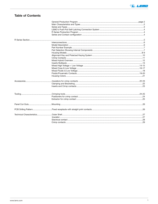
Table of Contents
General Production Program. .............................................................................................................page 2
Main Characteristics and Types...................................................................................................................2
Series and Types ..........................................................................................................................................3
LEMO's Push-Pull Self-Latching Connection System ................................................................................4
R Series Production Program ......................................................................................................................4
Series and Contact configuration ................................................................................................................4
R Series Section...............................................................................................................................................................................................................5
Interconnections ...........................................................................................................................................6
Model Description ........................................................................................................................................6
Part Number Example ..................................................................................................................................7
Part Selection Showing Internal Components ............................................................................................7
Housing Models ........................................................................................................................................8-9
Alignment Key and Polarized Keying System ...........................................................................................10
Crimp Contacts ..........................................................................................................................................11
Mixed Hybrid Overview ..............................................................................................................................12
Inserts Multipole .........................................................................................................................................13
Mixed High Voltage + Low Voltage. .....................................................................................................14-15
Mixed Coax & Low Voltage ..................................................................................................................16-17
Mixed Fluidic & Low Voltage......................................................................................................................18
Fluidic/Pnuematic Contacts..................................................................................................................19-20
Housing Colors ...........................................................................................................................................21
Accessories................................................Insulators for crimp contacts ...............................................................................................................22-23
Clamping and Bracketing...........................................................................................................................22
Inserts and Crimp contacts........................................................................................................................23
Tooling........................................................Crimping tools.......................................................................................................................................24-25
Positioners for crimp contact .....................................................................................................................24
Extractor for crimp contact ........................................................................................................................25
Panel Cut-Outs..........................................Mounting .....................................................................................................................................................26
PCB Drilling Pattern...................................Fixed receptacle with straight print contacts ............................................................................................26
Technical Characteristics...........................Outer Shell..................................................................................................................................................27
Insulator ......................................................................................................................................................27
Electrical contact ........................................................................................................................................28
Crimp contacts ...........................................................................................................................................29
www.lemo.com 1
Page3
® ®
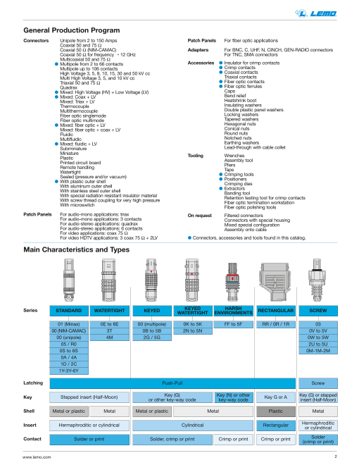
General Production Program
Connectors Unipole from 2 to 150 Amps Patch Panels For fiber optic applications
Coaxial 50 and 75 Ω
Coaxial 50 Ω (NIM-CAMAC) Adapters For BNC, C, UHF, N, CINCH, GEN-RADIO connectors
Coaxial 50 Ω for frequency Õ 12 GHz For TNC, SMA connectors
Multicoaxial 50 and 75 Ω
l Multipole from 2 to 66 contacts Accessories l Insulator for crimp contacts
Multipole up to 106 contacts l Crimp contacts
High Voltage 3, 5, 8, 10, 15, 30 and 50 kV cc l Coaxial contacts
Multi High Voltage 3, 5, and 10 kV cc Triaxial contacts
Triaxial 50 and 75 Ω l Fiber optic contacts
Quadrax l Fiber optic ferrules
l Mixed: High Voltage (HV) + Low Voltage (LV) Caps
l Mixed: Coax + LV Bend relief
Mixed: Triax + LV Heatshrink boot
Thermocouple Insulating washers
Multithermocouple Double plastic panel washers
Fiber optic singlemode Locking washers
Fiber optic multimode Tapered washers
l Mixed: fiber optic + LV Hexagonal nuts
Mixed: fiber optic + coax + LV Conical nuts
Fluidic Round nuts
Multifluidic Notched nuts
l Mixed: fluidic + LV Earthing washers
Subminiature Lead-through with cable collet
Miniature
Plastic Tooling Wrenches
Printed circuit board Assembly tool
Remote handling Pliers
Watertight Taps
Sealed (pressure and/or vacuum) l Crimping tools
l With plastic outer shell l Positioners
With aluminum outer shell Crimping dies
With stainless steel outer shell l Extractors
With special radiation resistant insulator material Banding tool
With screw thread coupling for very high pressure Retention testing tool for crimp contacts
With microswitch Fiber optic termination workstationFiber optic polishing tools
Patch Panels For audio-mono applications: triax On request Filtered connectors
For audio-mono applications: 3 contacts Connectors with special housing
For audio-stereo applications: quadrax Mixed special configuration
For audio-stereo applications: 6 contacts Assembly onto cable
For video applications: coax 75 Ω
For video HDTV applications: 3 coax 75 Ω + 2LV l Connectors, accessories and tools found in this catalog.
Main Characteristics and Types
Series STANDARD WATERTIGHT KEYED KEYED HARSHWATERTIGHT ENVIRONMENTS RECTANGULAR SCREW
01 (Minax) 0E to 6E 00 (multipole) 0K to 5K FF to 5F RR / 0R / 1R 03
00 (NIM-CAMAC) 3T 0B to 5B 2N to 5N 0V to 5V
00 (unipole) 4M 2G / 5G 0W to 5W
05 / R0 2U to 5U
0S to 6S 0M-1M-2M
0A / 4A
1D / 2C
1Y-3Y-6Y
Latching Push-Pull Screw
Key Stepped insert (Half-Moon) Key (G) Key (N) or otheror other key-way code key-way code Key G or A
Key (G) or stepped
insert (Half-Moon)
Shell Metal or plastic Metal Metal or plastic Metal Plastic Metal
Insert Hermaphroditic or cylindrical Cylindrical Rectangular Hermaphroditic or cylindrical
Contact Solder or print Solder, crimp or print Crimp or print Crimp or print Solder(crimp or print)
www.lemo.com 2
Page4
® ®
Series and Types
Types
Series
01 l
00 l l l l
05 l
R0 l
0A l l
0S l l l l l l
1S l l l l l l l
l l l l l l l l l
Standard 2S
3S l l l l l l l l l l
4S l l l l l l l l l l l
5S l l l l l l l l
6S l l l
1D l
2C l l
4A l
1Y-3Y-6Y l
0E l l l l l l
1E l l l l l l l
2E l l l l l l l l l
3E l l l l l l l l l l
Watertight 4E l l l l l l l l
5E l l l l l l
6E l l l
3T l l
4M l l
00 l l
0B l l l l
1B l l l
2B l l l l l l l l l
Keyed 3B l l l l l l l l l
4B l l l l l l l l l l
5B l l l l l l l
2G l
5G l
0K l l l l
1K l l l
2K l l l l l l l l
Keyed 3K l l l l l l l l l l
watertight 4K l l l l l l l l l l
5K l l l l l l l
FF to 5F l
2N to 5N l
RR l l
Rectangular 0R l l l l
1R l l l l
03 l l
0V l l l l l
1V l l l l l l
2V l l l l l l l l
l l l l l l l l l
Screw 3V
4V l l l l l l l l
5V l l l l l l
0W to 5W l l l l l l l l
2U to 5U l l l l
0M to 2M l
Note: l = included in this catalog, l = available but not included in this catalog.
www.lemo.com 3
Unipole
Coaxial 50 Ω
Coaxial 75 Ω
Multipole
High Voltage
Triaxial 50 Ω
Triaxial 75 Ω
Quadrax
Multi HV
Multi Coaxial
Mixed HV+LV
Mixed Coax+LV
Mixed Triax+LV
Fiber Optic
Multi FO
Mixed FO+LV
Fluidic
Multi fluidic
Mixed fluidic+LV
Thermocouple
Page5
® ®
LEMO’s Push-Pull Self-Latching Connection System
This self-latching system is renowned worldwide for its easy and quick mating and unmating features. It provides absolute
security against vibration, shock or pull on the cable, and facilitates operation in a very limited space.
The plug and the receptacle can be mated
by simply pushing axially the outer shell of the plug.
Pulling on the cable or any other component
of the plug than the outer release sleeve
cannot break the connection.
The connector can be unmated by a single axial
pull on the plug outer release sleeve.
R Series Production Program
Series RR 0R 1R
min. 1.0 1.5 2.0
Cable ø range (mm)
max. 4.0 6.2 9.2
Number of contacts (multipole) 13 10, 17, 37 28, 36, 67
Number of contacts (mixed HV+LV) – 4 HV + 4 LV, 2 HV + 13 LV 8 HV + 3 LV
Number of contacts (mixed coax+LV) 1 coax + 4 LV 4 coax + 4 LV, 2 coax + 13 LV 8 coax + 3 LV
Number of contacts (mixed fluidic+LV) – 4 fluidic + 4 LV, 2 fluidic + 13 LV 8 fluidic + 3 LV
Note: «LV» stands for low voltage.
www.lemo.com 4
Page6
R SERIES
Page7
® ®
R Series
The R series is a rectangular connector with high pin density in a flat profile. It uses LEMO’s well proven Push-Pull
latching system for a smooth, hassle free connection. The ergonomic and flat profile offers high panel density, in a wide
choice of colors for excellent visual aesthetics.
The R series is made of lightweight polyester resin Crastin® PBT from DupontTM. The high flexibility of its design enables
various contact configuration, such as multipole, coaxial, high voltage and fluidic.
R series connectors provide the following main features:
– plastic shell for lightweight yet rugged structure – high pin density for improved panel space
– push-pull latching enable fast and secure connections – 3 sizes and various models for design choices
– crimp or printed circuit contacts – standard or hybrid pin configurations for flexibility
– choice of 4 colors for aesthetics – thin footprint for reduced rack space
and quick identification and high density panel.
The R series, is initially designed to interconnect systems in medical application where aesthetics and safety is required.
This connector series can also be used for test & measurement, aerospace and automotive testing, where an extensive
number of contacts are needed in a limited space.
Plastic material used for manufacturing insulators is selected according to the required electric and thermal properties.
The thermoplastic used is PEEK (Polyether-Etherketone) with the addition of glass fibers to improve mechanical charac-
teristics and to increase dielectric strength.
Plastic housing models
Straight plug Fixed receptacles Free receptacles
EGG PHG
FGG
EBG PBG
www.lemo.com 6
Page8
® ®
Part Numbering System
Plug FG G . 1R . 336 . G L C 92
Free receptacle PH G . 1R . 336 . G L M 92
Fixed receptacle EG G . 1R . 336 . G L M
Variant:Cable Group: (page 17)
Model: (page 8-9) Cable ø: (page 22)
Alignment key: (page 10) Contact: (page 11)
Series: (page 12) Insulator: L = PEEK
Insert configuration: (page 13-18) Housing color: (page 21)
Part Number Example
Straight plug with cable collet:
FGG.1R.336.GLC92 = straight plug with key (G) and cable collet, 1R series, multipole type with 36 contacts, outer shell in
gray PBT, PEEK insulator, male crimp contacts, collet for 9.2 mm maximum diameter cable.
Free receptacle:
PHG.1R.336.GLM92 = free receptacle with key (G) and cable collet, 1R series, multipole type with 36 contacts, outer shell
in gray PBT, PEEK insulator, female crimp contacts, collet for 9.2 mm maximum diameter cable.
Fixed receptacle:
EGG.1R.336.GLM = fixed receptacle, nut fixing, with key (G), 1R series, multipole type with 36 contacts, outer shell in gray
PBT, PEEK insulator, female crimp contacts.
Part Section Showing Internal Components
2 3 4 5 6 1 2 4 3 5 1 6
Fixed receptacle
Straight plug
1 outer shell
1 outer shell
2 hexagonal nut
2 latch sleeve
3 locking washer
3 screw
4 screw
4 insulator
5 insulator
5 male contact
6 female contact
6 cable clamping
www.lemo.com 7
Page9
® ®
Housing models
FGG Straight plug, key (G) or key (A),
L with cable collet
B M
Reference Dimensions (mm)
Model Series A B L M
FGG RR 18.0 6.0 21.5 17.0
FGG 0R 24.5 9.0 30.5 23.5
FGG 1R 37.0 12.5 39.0 31.0
EGG Fixed receptacle, key (G) or key (A)
L
B M
Reference Dimensions (mm)
Model Series A B L M
EGG RR 18.0 6.0 12.0 7.0
EGG 0R 24.5 9.0 14.0 12.0
EGG 1R 37.0 12.5 18.0 14.5
P1 Panel cut-out page 26)
EGG Fixed socket, key (G) or key (A) with
L visible shell
B M
Reference Dimensions (mm)
Model Series A B L M
EGG RR 18.0 6.0 12.0 7.0
EGG 0R 24.5 9.0 14.0 12.0
EGG 1R 37.0 12.5 18.0 14.5
P1 Panel cut-out page 26)
www.lemo.com 8
A A
A
Page10
® ®
L EBG Fixed receptacle, key (G) or key (A), with flange
M
E
B
Reference Dimensions (mm)
Model Series A B C E G L M
EBG 1R 37.0 15.0 51.0 4.5 3.2 19.5 14.5
EBG 0R 24.5 10.5 24.5 3.2 2.2 18.0 12.0
P2 Panel cut-out page 26
ø G
PHG Free receptacle, key (G) or key (A), with
cable collet
B L
Reference Dimensions (mm)
Model Series A B L
PHG RR 18.0 6.0 22.3
PHG 0R 24.5 9.0 31.5
PHG 1R 37.0 12.5 39.0
PBG Fixed receptacle, key (G) or key (A),
L with flange and cable collet
E
B
Reference Dimensions (mm)
Model Series A B C E G L
PBG 1R 37.0 15.0 51.0 4.5 3.2 39.0
PBG 0R 24.5 10.5 34.5 3.2 2.2 31.5
P2 Panel cut-out page 26
ø G
www.lemo.com 9
C
C
A
A A
Page11
® ®
Alignment Key
Alignment Key and Polarized Keying System
R series connector model part numbers are composed of three letters. The LAST LETTER indicates the key position.
Front view of a receptacle
Series Contact type
Nb of
keys Note
RR 0R 1R Plug Receptacle
α 50° 50° 50° male female l
llG 2
β 30° 30° 30° male female l
α 42° 42° 42° male female l
llA 2
γ 30° 30° 30° male female l
l First choice alternative
l Special order alternative
www.lemo.com 10
Model
Angles
Page12
® ®
Crimp Contacts
Contacts for plugs, free or fixed receptacles Dimension of crimp barrels
Contact Ref. contact type Conductor
Ref. Contact type Ref. Contact type
ø A ø C Form AWG Section (mm2)Male Female
C Male crimp (fig. 1)1) P Female crimp (fig. 2)1) (mm) (mm) per fig. min. max. min. max.
B Male crimp (fig. 2)1) U Female crimp (fig. 2)1) 0.5 0.45 1 C M 32 28 0.035 0.09
G Male crimp (fig. 2)1) N Female straight print 0.80 1 C M 26 22 0.140 0.34
0.7
M Female crimp (fig. 1)1) 0.45 2 B P 32 28 0.035 0.09
1.10 1 C M 24 20 0.250 0.50
Note: 1) there are two forms of crimp barrels. Please consult adjacent
table for contact selection 0.9 0.80 2 B P 26 22 0.140 0.34
0.45 2 G U 32 28 0.035 0.09
Contacts reference for plugs, free or fixed receptacles
Conductor
Reference Contact
Stranded
Contact type AWG Section (mm2)
Male Female ø A ø C Form(mm) (mm) per fig. min. max. min. max.
Crimp C M 0.5 0.45 1 32 28 0.035 0.09
fig. 1 fig. 2
ø A ø C ø A ø C C M 0.80 1 26 221) 0.140 0.34
0.7
B P 0.45 2 32 28 0.035 0.09
ø A ø C ø A ø C C M 1.10 1 24 20 0.250 0.50
B P 0.9 0.80 2 26 221) 0.140 0.34
G U 0.45 2 32 28 0.035 0.09
Print
ø A ø C
C dimensions are detailed
– N in the section on PCB drilling pattern.
See page 26.
Note: 1) for a given AWG, the diameter of some stranded conductor designs is larger than the crimp barrel diameter.
Make sure that the maximum conductor diameter is smaller than ø C.
www.lemo.com 11
Page13
® ®
Mixed / Hybrid Overview
Size Ref Number of Diameter Number of Hybrid Insert
LV Contact and Type
Contacts
RR 804 4 0.5mm 1 coax, 50 ohm
4 pneumatic/fluidic
0R 004 4 0.7mm 5 bars max pressure
3mm tube diameter
4 high voltage
0R 704 4 0.7mm 2.7 kV rms (test volt)
7.5 kV dc (test volt)
0R 804 4 0.7mm 4 coax, 50 ohms
0R 813 13 0.7mm 2 coax, 50 ohm
8 high voltage
1R 703 3 0.9mm 2.7 kV rms (test volt)
7.5 kV dc (test volt)
1R 803 3 0.9mm 8 coax, 50 ohm
1R 855 22 0.5mm 1 coax, 50 ohm
33 0.7mm
www.lemo.com 12
Page14
® ®
Insert configuration
Multipole
Contact type Crimpcontact
Male crimp contacts Female crimp contacts
RR 1 1
313 13 0.5 l l – 0.6 0.5
13 13
0R 6 1 1 6 310 10 0.9 l l – 1.5 3.5
12 1 10 5 1 12 5 10
7 7
317 17 0.7 l l l 1.35 2.0
11 11
17 6 31 1 6 17 1 31
337 37 0.5 l l – 0.6 0.5
37 7 7 37
1R
1 1
22 9 9 22
16 16 328 28 0.9 l l – 1.5 3.0
21 21
28 15 15 28
8 8
1 1
20 11 11 20
29 29
336 36 0.7 l l – 1.5 2.5
36 36
28 19 19 28
10 10
56 1 1 56
365 65 0.5 l l – 0.6 0.5
65 65
11 11
58 1 1 58
367 67 0.5 l l – 0.6 0.5
67 67
11 11
www.lemo.com 13
Reference
Number of contacts
ø A (mm)
Crimp
Print (straight)
Print (elbow)
Test voltage (kV rms)1)
Contact-contact
Rated current (A)1)
Page15
® ®
Mixed: High Voltage + Low Voltage
High Voltage (HV) Low Voltage (LV)
Male HV contacts Female HV contacts
0R 1 1
704 4 7.5 2.0 4 0.7 l 1.35 2.0
2 2
3 3
11 1 4 1 11 4
713 2 7.5 2.0 13 0.7 l 1.35 3.0
7 7
1R
E A A E
1 1
F B B F
2 2 703 8 7.5 2.0 3 0.9 l 1.5 3.5G C C G
3 3
H D D H
www.lemo.com 14
Reference
Number of Contacts
Test voltage (kV dc)1)
Rated current (A)
Number of contacts
ø A (mm)
Crimp
Test voltage (kV rms)1)
Contact-contact
Rated Current (A)1)
Page16
® ®
Male
FGG.0R.403.ZLME15
HV contact
Contact HT
Female
EGG.0R.403.ZLCE15
HV contact
Contact HT
Typical Assembly of High Voltage Contact
HV Contacts: Fit the HV sleeve onto the cable dielectric, check that all
the HV conductor strands pass through the small hole.
Crimp the contact using tool DPC.91.701.V fitted with positioner
DCE.91.051.BVCM, set to position 3. Fit by turning the HV sub-assembly
on the HV sleeve and push until it butts. The two insulators should
be at the same level.
HV Contact Conductor Range 26-28 AWG
HV Contact Maximum Dielectric 1.5mm
www.lemo.com 15
Page17
® ®
Mixed Coax + Low Voltage
Coax Low voltage (LV)
Male coax contacts Female coax contacts
RR 3 1 1 3
804 1 0.5 RR 1 4 0.5 l 0.6 0.5
4 2 2 4
0R 1 1
804 4 50 0R 1 4 0.7 l 1.35 2
2 2
3 3
11 1 4 1 11 4
813 2 50 0R 1 13 0.7 l 1.35 2
7 7
1R
E A A E
1 1
F B B F 803 8 50 1R 1 3 0.9 l 1.5 3
2 2
G C C G
3 3
H D D H
1 1
22 0.5 l 0.6 0.5
855 1 50 1R 1
33 0.7 l 1.35 2.0
55 55
www.lemo.com 16
Reference
Number of contacts
Impedance (Ω)
Type
Cable group
Number of contacts
ø A (mm)
Crimp contact
Test voltage (kV rms)1)
Rated current (A)1)
Page18
® ®
Male
FGG.0R.250.ZLME28
Coax contact
Contact coax
Female
EGG.0R.250.ZLCE28
Coax contact
Contact coax
Typical Assembly of Coax Contact (Coax Types - RG-174/U, RG-188 A/U, RG-316/U) = Cable Group 1
Coax contacts: Fit the crimp ferrule onto the cable. Crimp the contact using tool DPC.91.701.V fitted with postion-
er DCE.91.050.RVCM, set to position 3. Fit by turning the coax sub-assembly on the central contact until the stop
is reached, check that the central contact is in the correct position in relation to the sub-assembly (0.5 mm), fold
back the cable screen, place the crimp ferrule over the crimping area and complete the crimp using tool
DPE.99.003.1K.
Male
Female
Typical Performance
VSWR / T.O.S.
www.lemo.com 17
Page19
® ®
Mixed: Fluidic + Low Voltage
Fluidic Low voltage (LV)
Male fluidic contacts Female fluidic contacts
0R 1 1
004 4 8 5 4 0.7 l 1.35 2.0
2 2
3 3
11 1 4 1 11 4
013 2 8 5 13 0.7 l 1.35 2.0
7 7
1R
E A A E
1 1
F B B F
2 2
G C C G 003 8 8 5 3 0.9 l 1.5 3.0
3 3
H D D H
www.lemo.com 18
Reference
Number of contacts
Flow (l/min)
Operating pressure (bars)
Number of contacts
ø A (mm)
Crimp contact
Test voltage (kV rms)1)
Rated current (A)1)
Page20
® ®
Fluidic / Pneumatic Contacts
Fluidic / pneumatic male contact
FGG.0R.010.AZ05 Male fluidic / pnuematic contact
Part number
FGG.0R.010.AZ05 (2.7mm hose barb and valve)
Note: 3 – Hose fitting/ barb, 2 – retaining clips, 1 – male sleeve
Fluidic / pneumatic male contact
FGG.0R.010.AZL05 Male fluidic /pnuematic contact
Part number
FGG.0R.010.AZL05 (1.7mm hose barb and non-valve)
Note: 3 – Hose fitting/ barb, 2 – retaining clips, 1 – male sleeve
www.lemo.com 19