


IP 68 PUSH-PULL CONNECTORS
※レモコネクタはモジュール方式のため、共通部品を組み合せることにより様々なコネクタに変えることができます。このため、カタログに掲載されている写真や図は、色、形状などが実物とは微妙に異なっている場合や、写真撮影の方向が一定していない場合がございます。ご注意いただきますようお願いいたします。
※技術特性につきましては、「技術カタログ 単極・多極コネクタ」をご覧ください。
◆詳細はカタログをダウンロードしご覧いただくか、お気軽にお問い合わせ下さい。
このカタログについて
| ドキュメント名 | コネクタ Tシリーズ(超小型防水) |
|---|---|
| ドキュメント種別 | 製品カタログ |
| ファイルサイズ | 10.1Mb |
| 登録カテゴリ | |
| 取り扱い企業 | レモジャパン株式会社 (この企業の取り扱いカタログ一覧) |
この企業の関連カタログ


このカタログの内容
Page1
T SERIES
IP 68 PUSH-PULL CONNECTORS
Page2
® ®
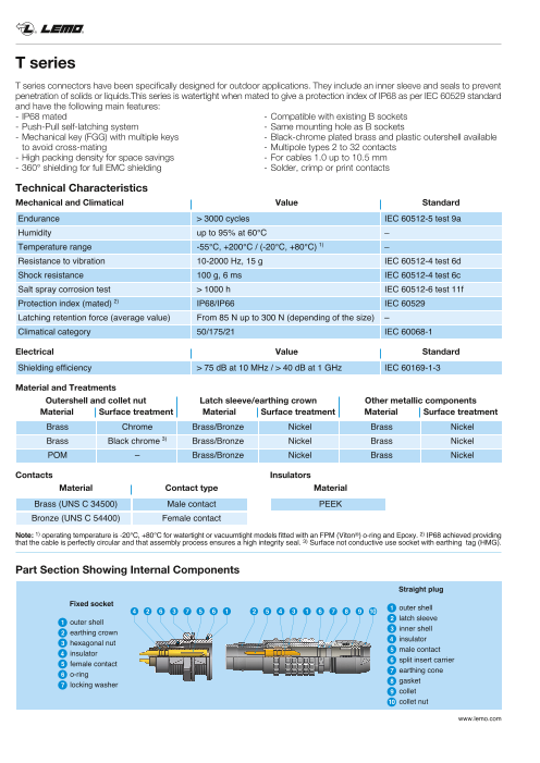
T series
T series connectors have been specifically designed for outdoor applications. They include an inner sleeve and seals to prevent
penetration of solids or liquids.This series is watertight when mated to give a protection index of IP68 as per IEC 60529 standard
and have the following main features:
- IP68 mated - Compatible with existing B sockets
- Push-Pull self-latching system - Same mounting hole as B sockets
- Mechanical key (FGG) with multiple keys - Black-chrome plated brass and plastic outershell available
to avoid cross-mating - Multipole types 2 to 32 contacts
- High packing density for space savings - For cables 1.0 up to 10.5 mm
- 360° shielding for full EMC shielding - Solder, crimp or print contacts
Technical Characteristics
Mechanical and Climatical Value Standard
Endurance > 3000 cycles IEC 60512-5 test 9a
Humidity up to 95% at 60°C –
Temperature range -55°C, +200°C / (-20°C, +80°C) 1) –
Resistance to vibration 10-2000 Hz, 15 g IEC 60512-4 test 6d
Shock resistance 100 g, 6 ms IEC 60512-4 test 6c
Salt spray corrosion test > 1000 h IEC 60512-6 test 11f
Protection index (mated) 2) IP68/IP66 IEC 60529
Latching retention force (average value) From 85 N up to 300 N (depending of the size) –
Climatical category 50/175/21 IEC 60068-1
Electrical Value Standard
Shielding efficiency > 75 dB at 10 MHz / > 40 dB at 1 GHz IEC 60169-1-3
Material and Treatments
Outershell and collet nut Latch sleeve/earthing crown Other metallic components
Material Surface treatment Material Surface treatment Material Surface treatment
Brass Chrome Brass/Bronze Nickel Brass Nickel
Brass Black chrome 3) Brass/Bronze Nickel Brass Nickel
POM – Brass/Bronze Nickel Brass Nickel
Contacts Insulators
Material Contact type Material
Brass (UNS C 34500) Male contact PEEK
Bronze (UNS C 54400) Female contact
Note: 1) operating temperature is -20°C, +80°C for watertight or vacuumtight models fitted with an FPM (Viton®) o-ring and Epoxy. 2) IP68 achieved providing
that the cable is perfectly circular and that assembly process ensures a high integrity seal. 3) Surface not conductive use socket with earthing tag (HMG).
Part Section Showing Internal Components
Straight plug
Fixed socket
4 2 6 3 7 5 6 1 2 5 4 3 1 6 7 8 9 10 1 outer shell
1 outer shell 2 latch sleeve
2 earthing crown 3 inner shell
3 hexagonal nut 4 insulator
4 insulator 5 male contact
5 female contact 6 split insert carrier
6 o-ring 7 earthing cone
7 locking washer 8 gasket
9 collet
10 collet nut
www.lemo.com
Page3
® ®
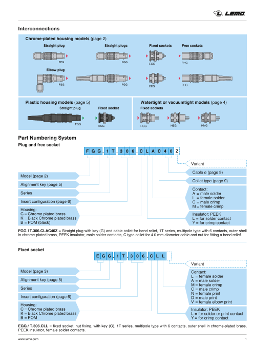
Interconnections
Chrome-plated housing models (page 2)
Straight plug Straight plugs Fixed sockets Free sockets
FFG FGG EGG PHG
Elbow plug
FSG FGG EEG PHG
Plastic housing models (page 5) Watertight or vacuumtight models (page 4)
Straight plug Fixed socket Fixed sockets
FGG EGG HGG HEG HMG
Part Numbering System
Plug and free socket
F G G . 1 T . 3 0 6 . C L A C 4 0 Z
Variant
Cable ø (page 9)
Model (page 2)
Collet type (page 9)
Alignment key (page 5)
Contact:
Series A = male solder
L = female solder
Insert configuration (page 6) C = male crimp
M = female crimp
Housing:
C = Chrome plated brass Insulator: PEEK
K = Black Chrome plated brass L = for solder contact
B = POM (black) Y = for crimp contact
FGG.1T.306.CLAC40Z = Straight plug with key (G) and cable collet for bend relief, 1T series, multipole type with 6 contacts, outer shell
in chrome-plated brass, PEEK insulator, male solder contacts, C type collet for 4.0 mm diameter cable and nut for fitting a bend relief.
Fixed socket
E G G . 1 T . 3 0 6 . C L L
Variant
Model (page 3) Contact:
L = female solder
Alignment key (page 5) A = male solder
M = female crimp
Series C = male crimp
N = female print
Insert configuration (page 6) D = male print
Housing: V = female elbow print
C = Chrome plated brass Insulator: PEEK
K = Black Chrome plated brass L = for solder or print contact
B = POM Y = for crimp contact
EGG.1T.306.CLL = fixed socket, nut fixing, with key (G), 1T series, multipole type with 6 contacts, outer shell in chrome-plated brass,
PEEK insulator, female solder contacts.
www.lemo.com 1
Page4
® ®
Chrome-plated housing models
FGG Straight plug, cable collet
Reference Dimensions (mm) Cable ø
~L Model Series A L M S1 S2 min. max.
~M
FGG TT 7.0 33.2 25.2 5.5 5 2.4 3.0
FGG 0T 9.5 39.0 29.0 7.5 7 1.0 5.0
S 2 S 1 FGG 1T 12.0 46.0 35.0 11.0 9 1.3 6.5
FGG 2T 15.0 55.0 43.0 14.0 12 1.3 8.5
FGG 3T 18.8 64.0 49.0 16.0 14 2.6 10.5
FGG Straight plug, cable collet and nut for fitting a bend relief
Reference Dimensions (mm) Cable ø
~L Model Series A L M S1 S2 min. max.
~M
FGG TT 7.0 32.7 24.7 5.5 6 2.4 3.0
FGG 0T 9.5 38.0 28.0 7.5 7 1.0 5.0
S 2 S 1 FGG 1T 12.0 45.0 34.0 11.0 9 1.3 6.5
FGG 2T 15.0 54.0 42.0 14.0 12 1.3 8.5
FGG 3T 18.8 62.0 47.0 16.0 15 2.6 10.5
FFG Straight plug, non latching, cable collet
Reference Dimensions (mm) Cable ø
~L Model Series A L M S1 S2 min. max.
~M
FFG TT 7.0 33.2 25.2 5.5 5 2.4 3.0
FFG 0T 9.5 39.0 29.0 8.0 7 1.0 5.0
S 2 S 1 FFG 1T 12.0 46.0 35.0 10.0 9 1.3 6.5
FFG 2T 15.0 55.0 43.0 13.0 12 1.3 8.5
FFG 3T 18.8 64.0 49.0 16.0 14 2.6 10.5
FSG Adjustable right angle plug
L
M Reference Dimensions (mm) Cable ø
Model Series A H L M S1 S2 min. max.
FSG TT 8 20.0 28.5 20.5 5 7.5 2.4 3.0
S 2
FSG 0T 10 23.0 36.0 26.0 7 9.5 1.0 5.0
S 1
FSG 1T 13 30.0 43.5 32.5 9 12.0 1.3 6.5
FSG 2T 17 37.5 54.0 42.0 12 16.0 1.3 8.5
2 www.lemo.com
~H
ø A ø A ø A ø A
Page5
® ®
PHG Free socket, cable collet
Reference Dimensions (mm) Cable ø
Model Series A L S1 S2 min. max.
~L
PHG TT 7.0 32.0 5.5 5 2.4 3.0
PHG 0T 9.5 38.0 8.0 7 1.0 5.0
S 2 S 1 PHG 1T 12.0 43.5 10.0 9 1.3 6.5
PHG 2T 15.0 52.0 14.0 12 1.3 8.5
PHG 3T 18.8 61.5 16.0 14 2.6 10.5
PHG Free socket, cable collet and nut for fitting a bend relief
Reference Dimensions (mm) Cable ø
Model Series A L S1 S2 min. max.
~L
PHG TT 7.0 31.5 5.5 6 2.4 3.0
PHG 0T 9.5 37.0 8.0 7 1.0 5.0
S 2 S 1 PHG 1T 12.0 42.5 10.0 9 1.3 6.5
PHG 2T 15.0 51.0 14.0 12 1.3 8.5
PHG 3T 18.8 60.0 16.0 15 2.6 10.5
EGG Fixed socket, nut fixing
Reference Dimensions (mm)
L maxi
N Model Series A B e E L M N1) S1 S2
S 2 M
EGG TT 10.0 10.2 M7x0.5 5.5 16.0 1.2 13.5 6.3 9
EGG 0T 12.0 12.5 M9x0.6 6.0 21.0 1.5 19.1 8.2 11
EGG 1T 15.5 16.0 M12x1.0 6.0 23.0 1.8 21.5 10.5 14
E maxi S 1
EGG 2T 18.5 19.6 M15x1.0 7.5 26.5 1.8 24.6 13.5 17
Note: 1) maximum length with crimp contacts. EGG 3T 23.5 25.1 M18x1.0 9.6 30.1 2.5 25.0 16.5 22
EEG Fixed socket, nut fixing, back panel mounting
Reference Dimensions (mm)
L maxi
N Model Series A B e E L N1) P S1
EEG TT 10.0 10.0 M7x0.5 4.5 16.0 13.5 7 6.3
EEG 0T 12.0 12.0 M9x0.6 6.5 21.0 19.1 9 8.2
E maxi S 1 EEG 1T 15.5 16.0 M12x1.0 6.5 23.0 21.5 10 10.5
P
EEG 2T 18.5 20.0 M15x1.0 7.5 26.5 24.6 11 13.5
Note: 1) maximum length with crimp contacts. EEG 3T 23.5 24.0 M18x1.0 7.5 30.1 25.0 12 16.5
Panel cut-out
Reference Panel cut-out Mounting nut torque
Model Series B C L Metal shell Plastic shell
L mini
Ell TT 6.4 7.1 12.5 1.0 0.4
Ell 0T 8.3 9.1 14.5 2.5 0.4
B
+ 0.1 Ell 1T 10.6 12.1 18.5 4.5 0.7
0
Ell 2T 13.6 15.1 22.5 6.0 0.8
Ell 3T 16.6 18.1 27.0 9.0 1.0
3
ø C
+ 0.1
0
ø A ø B
e
e
ø B ø A
ø A ø A
Page6
® ®
Watertight or vacuumtight models
These models are identified by a letter «P» at the end of the reference. Most of these models are also available in a vacuum-
tight version. Such models are identified by an additional letter «V» at the end of the part number (certificate on request).
Epoxy resin is used to seal these models. The temperature range is -20°C / +80°C.
Part Number Example
HGG.0T.305.CLLP (5 contacts, resin potted)
HGG.0T.305.CLLPV (5 contacts, resin potted and vacuumtight tested)
HGG Fixed socket, nut fixing, watertight or vacuumtight
L maxi Reference Dimensions (mm)
N
S 2 M Model Series A B e E L M N1) S1 S2
HGG TT 10.0 10.2 M7x0.5 5.5 18.0 1.2 15.0 6.3 9
HGG 0T 12.0 12.5 M9x0.6 6.5 22.0 1.5 18.5 8.2 11
E maxi S 1 HGG 1T 15.5 16.0 M12x1.0 6.0 26.0 1.8 21.5 10.5 14
HGG 2T 18.5 19.6 M15x1.0 8.0 30.5 1.8 25.0 13.5 17
HEG Fixed socket, nut fixing, watertight or vacuumtight, back panel mounting
L maxi Reference Dimensions (mm)
N
Model Series A B e E L N P S1
HEG TT 10.0 10.0 M7x0.5 4.5 18.0 15.0 7 6.3
HEG 0T 12.0 12.0 M9x0.6 6.5 22.0 18.5 9 8.2
E maxi S 1
P HEG 1T 15.5 16.0 M12x1.0 6.5 26.0 21.5 10 10.5
HEG 2T 18.5 20.0 M15x1.0 7.5 30.5 25.0 11 13.5
HMG Fixed socket with earthing tag, nut fixing, watertight or vacuumtight, back panel mounting
L maxi Reference Dimensions (mm)
N
Model Series A B e E L N P S1
HMG TT 10.0 10.0 M7x0.5 4.5 18.0 15.0 7 6.3
HMG 0T 12.0 12.0 M9x0.6 6.5 22.0 18.5 9 8.2
E maxi S 1
P HMG 1T 15.5 16.0 M12x1.0 6.5 26.0 21.5 10 10.5
HMG 2T 18.5 20.0 M15x1.0 7.5 30.5 25.0 11 13.5
Panel cut-out
Reference Panel cut-out Mounting nut torque
L mini Model Series B C L Metal shell Plastic shell
Hll TT 6.4 7.1 12.5 1.0 0.4
Hll 0T 8.3 9.1 14.5 2.5 0.4
B + 0.1 0 Hll 1T 10.6 12.1 18.5 4.5 0.7
Hll 2T 13.6 15.1 22.5 6.0 0.8
4 www.lemo.com
ø C + 0.1 0
ø A ø A ø B
e
e e
ø B ø B ø A
Page7
® ®
Plastic housing models
FGG Straight plug, cable collet and nut for fitting a bend relief, POM outer shell
~L
~M
Reference Dimensions (mm) Cable ø
S 2 Model Series A L M S2 min. max.
FGG 0T 9.7 38.5 28.5 8 1.0 5.0
FGG 1T 13.0 45.0 34.0 10 1.3 6.5
EGG Fixed socket, nut fixing, POM outer shell
L maxi
N
S 2 M
Reference Dimensions (mm)
Model Series A B e E L M N1) S1 S2
EGG 0T 12.0 12.5 M9x0.6 6.0 21.0 1.5 19.1 8.2 11
E maxi S 1
EGG 1T 15.5 16.0 M12x1.0 6.0 23.0 1.8 21.5 10.5 14
Note: 1) maximum length with crimp contacts.
Panel cut-out
L mini Reference Panel cut-out
Model Series B C L
Ell 0T 8.3 9.1 14.5
B
+ 0.1
0 Ell 1T 10.6 12.1 18.5
Alignment Key
Contact type
Plug Socket
G male female
G D J
A male female
A L
D male female
L female male
J female male
www.lemo.com 5
ø C + 0.1 0
ø B
e
Key
ø A
ø A
Page8
® ®
In sert configurations
Multipole
Solder contacts Contact AWG Soldertype contact
Crimp
1 4 4 1
2 3 Crimp contacts 3 2
2 TT 0.5 l l l l 30 32 28 1.00 0.95 3.5
0T 0.9 l l l l 20 32 20 1.00 1.05 10.0
302 1T 1.3 l l l l 20 26 18 1.50 1.35 15.0
2T 2.0 l l l l 16 18 12 2.10 1.75 25.0
3T 3.0 l l l – 12 14 10 2.10 1.55 35.0
3 TT 0.5 l l l l 30 32 28 0.80 0.95 3.0
0T 0.9 l l l l 20 32 20 1.20 0.90 8.0
303 1T 1.3 l l l l 20 26 18 1.30 1.55 12.0
2T 1.6 l l l l 18 22 14 2.40 1.85 17.0
3T 2.0 l l l l 16 18 12 1.90 1.50 25.0
4 TT 0.5 l l l l 30 32 28 0.80 0.65 2.0
0T 0.7 l l l l 22 32 22 0.85 0.70 7.0
304 1T 0.9 l l l l 22 32 20 1.35 1.45 10.0
2T 1.3 l l l l 20 26 18 1.85 1.85 15.0
3T 2.0 l l l l 16 18 12 1.45 1.25 19.0
5
305 TT 0.35 l – l – 30 – – 0.70 1.00 1.7
5 0T 0.7 l l l l 22 32 22 1.00 0.70 6.5
1T 0.9 l l l l 22 32 20 1.25 1.15 9.0
305
2T 1.3 l l l l 20 26 18 1.75 1.60 14.0
3T 1.6 l l l l 18 22 14 1.90 1.25 19.0
6
0T 0.5 l l1) l l 28 32 28 0.85 0.65 2.5
306
1T 0.7 l l l l 22 32 22 1.05 1.20 7.0
Note: 1) available only for connectors fitted with male contacts. l First choice alternative Special order alternative
6 www.lemo.com
Reference
Series
Contact ø (mm)
Solder
Crimp
Print (straight)
Print (elbow)
Solder (max.)
min.
max.
Test voltage (kV rms)
Contact-contact
Test voltage (kV rms)
Contact-shell
Rated current (A)
Page9
® ®
Multipole
Solder contacts Contact AWG Soldertype contact
Crimp
1 4 4 1
2 3 Crimp contacts 3 2
6 TT 0.35 l – – – 30 – – 0.60 0.75 1.5
306 2T 1.3 l l l l 20 26 18 1.35 1.45 12.0
3T 1.6 l l l l 18 22 14 1.60 1.15 17.0
7 0T 0.5 l l
1) l l 28 32 28 0.80 0.70 2.5
1T 0.7 l l l l 22 32 22 0.95 1.05 7.0
307
2T 1.3 l l l l 20 26 18 1.75 1.60 11.0
3T 1.6 l l l l 18 22 14 1.70 1.25 15.0
8
308 1T 0.7 l l l l 22 32 22 0.95 1.15 5.0
8 2T 0.9 l l l l 22 32 20 1.50 1.25 10.0
308
3T 1.3 l l l l 20 26 18 1.65 1.15 13.0
9 0T 0.5 l l1) l l 28 32 28 0.60 0.50 2.0
309
3T 8x1 .3 20 26 18 6.0 1x2.0 l l l – 16 18 12 1.3 5 1.0 5 15.0
10 1T 0.5 l l
1) l l 28 32 28 0.90 1.50 2.5
310 2T 0.9 l l l l 22 32 20 1.45 1.30 8.0
3T 1.3 l l l l 20 26 18 1.25 0.90 12.0
12
312 0T 0.35 l – l – 30 – – 0.80 1.00 1.5
12 2T 0.7 l l l l 22 32 22 1.25 1.35 7.0
312
3T 0.9 l l l l 22 32 20 1.45 1.00 9.0
14 1T 0.5 l l
1) l l 28 32 28 0.80 1.20 2.0
314 2T 0.7 l l l l 22 32 22 1.15 1.35 6.5
3T 0.9 l l l l 22 32 20 1.20 1.20 9.0
Note: 1) available only for connectors fitted with male contacts. l First choice alternative Special order alternative
www.lemo.com 7
Reference
Series
Contact ø (mm)
Solder
Crimp
Print (straight)
Print (elbow)
Solder (max.)
min.
max.
Test voltage (kV rms)
Contact-contact
Test voltage (kV rms)
Contact-shell
Rated current (A)
Page10
® ®
Multipole
Solder contacts Contact AWG Soldertype contact
Crimp
1 4 4 1
2 3 Crimp contacts 3 2
16
316 1T 0.5 l l1) l l 28 32 28 0.80 1.25 1.5
16 2T 0.7 l l l l 22 32 22 0.95 1.25 6.0
316
3T 0.9 l l l l 22 32 20 1.20 0.85 8.0
18 2T 0.7 l l l l 22 32 22 0.85 1.20 5.5
318
3T 0.9 l l l l 22 32 20 1.20 1.05 7.0
19
319 2T 0.7 l l l l 22 32 22 0.95 1.25 5.0
20
320 3T 0.7 l l l l 22 32 22 1.00 0.90 6.0
22
322 3T 0.7 l l l l 22 32 22 1.00 0.90 5.5
24
324 3T 0.7 l l l l 22 32 22 0.95 0.80 4.0
26 2T 0.5 l – l l 28 – – 0.95 1.30 2.0
326
3T 0.7 l l l l 22 32 22 0.95 0.70 4.0
30
330 3T 0.7 l l l l 22 32 22 0.80 0.70 3.5
32
332 2T 0.5 l – l l 28 – – 0.80 1.20 1.5
Note: 1) available only for connectors fitted with male contacts. l First choice alternative Special order alternative
8 www.lemo.com
Reference
Series
Contact ø (mm)
Solder
Crimp
Print (straight)
Print (elbow)
Solder (max.)
min.
max.
Test voltage (kV rms)
Contact-contact
Test voltage (kV rms)
Contact-shell
Rated current (A)
Page11
® ®
Collets
Cable ø (mm) Cable ø (mm) Cable ø (mm)
Type Note Type Note Type Note
min. max. min. max. min. max.
C27 2.4 2.6 C15 1.3 1.5 C30 2.6 3.0
TT
C31 2.7 3.0 2T C20 1.6 2.0 3T C35 3.1 3.5
C10 1.0 1.2 1) C25 2.1 2.5 C40 3.6 4.0
0T
C15 1.3 1.5 1) C30 2.6 3.0 C45 4.1 4.5
C20 1.6 2.0 1) C35 3.1 3.5 C50 4.6 5.0
C25 2.1 2.5 C40 3.6 4.0 C55 5.1 5.5
C30 2.6 3.0 C45 4.1 4.5 C60 5.6 6.0
C35 3.1 3.5 C50 4.6 5.0 C65 6.1 6.5
C40 3.6 4.0 C55 5.1 5.5 C70 6.6 7.0
C45 4.1 4.5 C60 5.6 6.0 C75 7.1 7.5
K50 4.6 5.0 2) C65 6.1 6.5 C80 7.6 8.0
K55 5.1 5.5 2) C70 6.6 7.0 C85 8.1 8.5
K60 5.6 6.0 2) C75 7.1 7.5 C90 8.6 9.0
K65 6.1 6.5 2) C80 7.6 8.0 C95 9.1 9.5
C15 1.3 1.5 C85 8.1 8.5 C10 9.6 10.0
1T
C20 1.6 2.0 K90 8.6 9.0 4) C11 10.1 10.5
C25 2.1 2.5 K95 9.1 9.5 4) K11 10.6 12.0
C30 2.6 3.0 K10 9.6 10.0 4) K12 12.1 12.8
C35 3.1 3.5 K11 10.1 10.5 4) K13 12.9 13.5
C40 3.6 4.0 K14 13.6 14.0
C45 4.1 4.5 K15 14.1 15.0 5)
C50 4.6 5.0
C55 5.1 5.5
C60 5.6 6.0
C65 6.1 6.5
K70 6.6 7.0 3)
K75 7.1 7.5 3)
K80 7.6 8.0 3)
K85 8.1 8.5 3)
Note: all dimensions are in millimetres.
1) the inner diameter of the smallest bend relief available is 2.5 mm (in TPU) / 1.7 mm (in silicone).
2) for 1B bend relief.
3) for 2B bend relief.
4) for 3B bend relief.
5) the inner diameter of the largest bend relief available is 14.5 mm.
www.lemo.com 9
Page12
® ®
Spare parts for crimp contacts
Insulator part number ø (mm) Cond. AWG Contact part number
Types
Male contact Female contact A C min. max. Male Female
TT 302 / 303 / 304 FGG.00.30l.YL EGG.00.40l.YL 0.5 0.45 1 32 28 FGG.00.554.ZZC EGG.00.654.ZZM
1.10 1 24 20 FGG.0B.560.ZZC EGG.0B.660.ZZM
0T 302 / 303 FGG.0B.30l.YL EGG.0B.40l.YL 0.9 0.80 2 26 22 FGG.0B.561.ZZC EGG.0B.661.ZZM
0.45 2 32 28 FGG.0B.562.ZZC EGG.0B.662.ZZM
0.80 1 26 22 FGG.0B.555.ZZC EGG.0B.655.ZZM
304 / 305 FGG.0B.30l.YL EGG.0B.40l.YL 0.7
0.45 2 32 28 FGG.0B.556.ZZC EGG.0B.656.ZZM
306 / 307 / 309 FGG.0B.30l.YL – 0.5 0.45 1 32 28 FGG.0B.554.ZZC –
1.40 1 20 18 FGG.1B.565.ZZC EGG.1B.665.ZZM
1T 302 / 303 FGG.1B.30l.YL EGG.1B.40l.YL 1.3 1.10 2 24 20 FGG.1B.566.ZZC EGG.1B.666.ZZM
1.10 1 24 20 FGG.1B.560.ZZC EGG.1B.660.ZZM
304 / 305 FGG.1B.30l.YL EGG.1B.40l.YL 0.9
0.80 2 26 22 FGG.1B.561.ZZC EGG.1B.661.ZZM
0.80 1 26 22 FGG.1B.555.ZZC EGG.1B.655.ZZM
306 / 307 / 308 FGG.1B.30l.YL EGG.1B.40l.YL 0.7
0.45 2 32 28 FGG.1B.556.ZZC EGG.1B.656.ZZM
310 / 314 / 316 FGG.1B.3ll.YL – 0.5 0.45 1 32 28 FGG.1B.554.ZZC –
2.40 1 16 12 FGG.2B.575.ZZC EGG.2B.675.ZZM
2T 302 FGG.2B.302.YL EGG.2B.402.YL 2.0 1.90 2 18 14 FGG.2B.576.ZZC EGG.2B.676.ZZM
1.90 1 18 14 FGG.2B.570.ZZC EGG.2B.670.ZZM
303 FGG.2B.303.YL EGG.2B.403.YL 1.6
1.40 2 22 18 FGG.2B.571.ZZC EGG.2B.671.ZZM
1.40 1 20 18 FGG.2B.565.ZZC EGG.2B.665.ZZM
304 / 305
306 /307 FGG.2B.30l.YL EGG.2B.40l.YL 1.3 1.10 2 24 20 FGG.2B.566.ZZC EGG.2B.666.ZZM
0.80 2 26 22 FGG.2B.567.ZZC EGG.2B.667.ZZM
1.10 1 24 20 FGG.2B.560.ZZC EGG.2B.660.ZZM
308 / 310 FGG.2B.3ll.YL EGG.2B.4ll.YL 0.9 0.80 2 26 22 FGG.2B.561.ZZC EGG.2B.661.ZZM
0.45 2 32 28 FGG.2B.562.ZZC EGG.2B.662.ZZM
3 12 / 314 / 316 0.80 1 26 22 FGG.2B.555.ZZC EGG.2B.655.ZZM
318 / 319 FGG.2B.3ll.YL EGG.2B.4ll.YL 0.7 0.45 2 32 28 FGG.2B.556.ZZC EGG.2B.656.ZZM
3T 302 FGG.3B.302.YL EGG.3B.402.YL 3.0 3.20 1 14 10 FGG.3B.580.ZZC EGG.3B.680.ZZM
2.40 1 16 12 FGG.3B.575.ZZC EGG.3B.675.ZZM
303 / 304 / 309 FGG.3B.30l.YL1) EGG.3B.40l.YL1) 2.0
1.90 2 18 14 FGG.3B.576.ZZC EGG.3B.676.ZZM
1.90 1 18 14 FGG.3B.570.ZZC EGG.3B.670.ZZM
305 / 306 / 307 FGG.3B.30l.YL EGG.3B.40l.YL 1.6
1.40 2 22 18 FGG.3B.571.ZZC EGG.3B.671.ZZM
1.40 1 20 18 FGG.3B.565.ZZC EGG.3B.665.ZZM
308 / 309 / 310 FGG.3B.3ll.YL1) EGG.3B.4ll.YL1) 1.3
1.10 2 24 20 FGG.3B.566.ZZC EGG.3B.666.ZZM
1.10 1 24 20 FGG.3B.560.ZZC EGG.3B.660.ZZM
312 / 314
316 /318 FGG.3B.3ll.YL EGG.3B.4ll.YL 0.9 0.80 2 26 22 FGG.3B.561.ZZC EGG.3B.661.ZZM
0.45 2 32 28 FGG.3B.562.ZZC EGG.3B.662.ZZM
320 / 322 / 324 0.80 1 26 22 FGG.3B.555.ZZC EGG.3B.655.ZZM
326 /330 FGG.3B.3ll.YL EGG.3B.4ll.YL 0.7 0.45 2 32 28 FGG.3B.556.ZZC EGG.3B.656.ZZM
Note: 1) for 309 type the insulator part number is FGG.3B.309.ML (male contact) and EGG.3B.409.ML (female contact).
10 www.lemo.com
Fig.
Page13
® ®
Tools for crimp contacts
Positioners part number Extractors part FGG-EGG Crimp contacts
Types number for male/
Male contact Female contact female contacts ø A Fig. 1 ø C
TT 302 / 303 / 304 DCE.91.050.0VC DCE.91.050.0VM DCF.91.050.2LT FGG
EGG ø A ø C
0T DCE.91.090.BVC DCE.91.090.BVM302 /303 DCF.91.090.2LT ø A Fig. 2 ø C
DCE.91.090.AVC DCE.91.090.AVM FGG
304 / 305 DCE.91.070.BVC DCE.91.070.BVM DCF.92.070.3LT EGG ø A ø C
306 / 307 / 309 DCE.91.050.BVC DCE.91.050.BVM DCF.91.050.2LT Note: a wide variation of strand number and diameter
combinations are quoted as being AWG, some of which
do not have a large enough cross section to guarantee
1T 302 /303 DCE.91.131.BVC DCE.91.131.BVM DCF.91.131.2LT a crimp as per either MIL-C-22520/1-01 or /7-01.
304 / 305 DCE.91.091.BVC DCE.91.091.BVM DCF.91.090.2LT FGG-EGG Insulators
FGG EGG
306 / 307 / 308 DCE.91.071.BVC DCE.91.071.BVM DCF.91.070.2LT
310 / 314 / 316 DCE.91.051.BVC DCE.91.051.BVM DCF.91.050.2LT male female
Note: each insulator can be used both for crimp con-
2T 302 DCE.91.202.BVCM DCC.91.202.5LA2) tacts of normal shape (fig. 1) or with reduced solder cups (fig. 2).
303 DCE.91.162.BVCM DCF.91.162.2LT DCE Positioners ø 0.5, 0.7, 0.9, 1.3 mm
304 / 305 DCE.91.132.BVC DCE.91.132.BVM
306 DCF.91.131.2LT / 307
DCE.91.132.CVC DCE.91.132.CVM
DCE.91.092.BVC DCE.91.092.BVM
308 / 310 DCF.91.090.2LT male female
DCE.91.092.AVC DCE.91.092.AVM
These positioners are suitable for use with both manual 312 / 314 / 316
318 /319 DCE.91.072.BVC DCE.91.072.BVM DCF.91.070.2LT
and pneumatic crimping tools according to the MIL-C-
22520/7-01 standard.
3T 302 DCE.91.303.BVCM DCF.91.303.5LT DCE Turret for ø 1.6, 2.0, 3.0, 4.0 mm
303 / 304 / 309 DCE.91.203.BVCM DCC.91.202.5LA2)
305 / 306 / 307 DCE.91.163.BVCM DCF.91.163.5LT
308 / 309 / 310 DCE.91.133.BVC DCE.91.133.BVM DCF.91.133.5LT Note: these turrets can be used with manual crimping
tool according to MIL-C-22520/1-01 standard.
312 / 314 DCE.91.093.BVC DCE.91.093.BVM
316 /318 DCF.91.093.5LT DCF Automatic extraction tools
DCE.91.093.BVG DCE.91.093.BVU
320 / 322 / 324
326 /330 DCE.91.073.BVC DCE.91.073.BVM DCF.92.070.3LT
Note: 2) this model is thumb-operated.
www.lemo.com 1 1
Page14
® ®
Spare parts
GBA Locking washers
Dimensions (mm)
ø A Part number Series A C L
ø C L
GBA.00.250.FN TT 9.5 7.1 1.0
GBA.0S.250.FN 0T 12.5 9.1 1.0
GBA.1S.250.FN 1T 16.0 12.1 1.0
GBA.2S.250.FN 2T 19.5 15.1 1.2
GBA.3S.250.FN 3T 25.0 18.1 1.4
Note: to order this accessory separately, use the above part numbers.
l Material: Nickel-plated bronze (3 µm)
GEA Hexagonal nuts
Dimensions (mm)
Part number Series
A B e L
A GEA.00.240.LN TT 9 10.2 M7 x 0.5 2.0
e L GEA.0S.240.LN 0T 11 12.4 M9 x 0.6 2.0
GEA.1S.240.LN 1T 14 15.8 M12 x 1.0 2.5
GEA.2S.240.LN 2T 17 19.2 M15 x 1.0 2.7
GEA.3S.240.LN 3T 22 25.0 M18 x 1.0 3.0
Note: to order this part separately, use the above part numbers. The last
letters «LN» of the part number refer to the nut material and treatment. If a
nut in aluminium alloy or stainless steel is desired, replace the last letters
of the part number by «PT» or «AZ» respectively.
See page 17 for the tooling.
l Material: Nickel-plated brass (3 µm), Natural anodized aluminium alloy, Stainless steel
GEC Conical nuts
Dimensions (mm)
Part number Series
A B e L
A GEC.00.240.LC TT 8 10 M7 x 0.5 2.5
e L GEC.0S.240.LC 0T 10 12 M9 x 0.6 2.5
GEC.1S.240.LC 1T 13 16 M12 x 1.0 3.2
GEC.2S.240.LC 2T 17 20 M15 x 1.0 3.8
GEC.3S.240.LC 3T 20 24 M18 x 1.0 4.5
Note: 3T series fixed and free sockets for back panel mounting are always
delivered with a conical nut.
To order this accessory separately, use the above part numbers.
See page 17 for the tooling.
l Material: Chrome-plated brass (Ni 3 µm + Cr 0.3 µm)
1 2 www.lemo.com
øB
ø B
Page15
® ®
GEG Notched nuts
ø A
e L
Dimensions (mm)
Model 1 Part number Series Model
A B e L
GEG.00.240.LC TT 8.6 10 M7 x 0.5 2.5 1
ø A
L GEG.0S.240.LC 0T 10.5 12 M9 x 0.6 2.5 1e
GEG.1S.240.LC 1T 14.0 16 M12 x 1.0 3.5 1
GEG.2S.240.LC 2T 17.5 20 M15 x 1.0 3.5 2
Note: TT, 0T, 1T and 2T series fixed and free sockets for back panel
mounting are always delivered with this notched nut.
Model 2 To order this accessory separately, use the above part numbers.See page 18 for the tooling.
l Material: Chrome-plated brass (Ni 3 µm + Cr 0.3 µm)
www.lemo.com 1 3
ø B ø B
Page16
® ®
Accessories
BFG Blanking caps for plugs BHG Blanking caps for fixed plugs
L L
B B
sliding loop ø 3.5
Dimensions (mm)
Part number Part number
A B L N1)
BFG.TT.100.CAS 7.0 4.3 9.0 60 BHG.TT.100.CAS
BFG.0T.100.CAS 9.5 5.0 11.0 85 BHG.0T.100.CAS l Body material: Chrome-plated brass (Ni 3 µm)
l Lanyard material: Stainless steel
BFG.1T.100.CAS 12.0 6.3 12.4 85 BHG.1T.100.CAS l Crimp ferrule material: Nickel-plated brass + polyolefin
l O-ring material: Silicone
BFG.2T.100.CAS 15.0 6.4 13.8 85 BHG.2T.100.CAS l Maximum operating temperature: 135°C
l Watertightness: IP68 according to IEC 60529
BFG.3T.100.CAS 18.8 6.4 17.6 120 BHG.3T.100.CAS Note: 1) the tolerance on this dimension is ± 5 mm.
BRF Blanking caps for free sockets BRE Blanking caps for sockets
B B
L L
M M
sliding loop ø 3.5
Dimensions (mm)
Part number Part number
A B L M N1)
BRF.TT.200.CAZ 7.0 4.3 10.4 2.4 60 BRE.TT.200.CAZ
BRF.0T.200.CAZ 9.5 5.0 13.2 3.2 85 BRE.0T.200.CAZ
l Body material: Chrome-plated brass (Ni 3 µm)
BRF.1T.200.CAZ 12.0 6.3 15.1 4.2 85 BRE.1T.200.CAZ l Lanyard material: Stainless steel
l Crimp ferrule material: Nickel-plated brass + polyolefin
BRF.2T.200.CAZ 15.0 6.4 17.1 5.2 85 BRE.2T.200.CAZ l Maximum operating temperature: 135°C
l Watertightness: IP68 according to IEC 60529
BRF.3T.200.CAZ 18.8 6.4 21.2 6.4 120 BRE.3T.200.CAZ Note: 1) the tolerance on this dimension is ± 5 mm.
14 www.lemo.com
N N
ø A ø A
N N
ø A ø A
Page17
® ®
GCA Earthing washers
ø A Dimensions (mm)
L Part number Seriesø B A B L N
GCA.00.255.LT TT 9.5 7.1 0.4 18.2
GCA.0S.255.LT 0T 13.0 9.1 0.4 22.0
GCA.1S.255.LT 1T 17.0 12.2 0.5 27.5
GCA.2S.255.LT 2T 20.0 15.2 0.5 32.0
GCA.3S.255.LT 3T 25.0 18.2 0.5 39.0
l Material: CuSnZn plated brass (2 µm)
Bend relief (TPU)
A bend relief made from thermoplastic polyurethane elas-
tomer can be fitted over LEMO plugs and sockets that are
supplied with nut for fitting such bend relief.
L They are available in nine different colours match with the GRA insulating washers.
Use the part numbers shown below to order this accessory
separately.
Bend relief Cable ø Bend relief Cable ø
Part number Part number
A L min. max. A L min. max.
GMB.00.025.DG 1) 2.5 22 2.5 2.8 GMA.2B.040.DG 4.0 36 4.0 4.5
TT
GMB.00.028.DG 1) 2.8 22 2.8 3.1 2T GMA.2B.045.DG 4.5 36 4.5 5.0
GMB.00.032.DG 1) 3.2 22 3.2 3.5 GMA.2B.050.DG 5.0 36 5.0 5.5
GMD.00.025.DG 1) 2.5 22 2.5 2.8 GMA.2B.060.DG 6.0 36 6.0 6.5
GMD.00.028.DG 1) 2.8 22 2.8 3.1 GMA.2B.070.DG 7.0 36 7.0 7.7
GMD.00.032.DG 1) 3.2 22 3.2 3.5 GMA.2B.080.DG 1) 7.8 36 7.8 8.8
GMA.0B.025.DG 2.5 24 2.5 2.9 GMA.3B.050.DG 1) 4.5 42 4.5 5.2
0T
GMA.0B.030.DG 3.0 24 3.0 3.4 3T GMA.3B.060.DG 6.0 42 6.0 6.9
GMA.0B.035.DG 3.5 24 3.5 3.9 GMA.3B.070.DG 7.0 42 7.0 7.9
GMA.0B.040.DG 1) 4.0 24 4.0 4.4 GMA.3B.080.DG 8.0 42 8.0 8.9
GMA.0B.045.DG 1) 4.5 24 4.5 5.2 GMA.3B.090.DG 9.0 42 9.0 10.0
GMA.1B.025.DG 2.5 30 2.5 2.9
1T Note: all dimensions are in millimetres.
GMA.1B.030.DG 3.0 30 3.0 3.4
GMA.1B.035.DG 3.5 30 3.5 3.9
Ref. Colour Ref. Colour Ref. Colour
GMA.1B.040.DG 4.0 30 4.0 4.4
GMA.1B.045.DG 4.5 30 4.5 4.9 A blue J yellow R red
GMA.1B.054.DG 5.4 30 5.4 6.0 B white M brown S orange
GMA.1B.065.DG 1) 6.5 30 6.5 7.0 G grey N black V green
Note: 1) Design may differ from other bend relief, model without stripes. The «GMD» are thin bend reliefs (for very flexible cables).
The last letter «G» of the part number indicates the grey colour of the bend relief. For ordering a bend relief with another colour, see table above and
replace the letter «G» by the letter of the required colour.
www.lemo.com 15
N
ø A
Page18
® ®
Tooling
DCG Spanners for hexagonal nuts
N
Dimensions (mm)
Part number Series Part number
B L N of the nut
DCG.91.149.0TN TT 14 40 50 GEA.00.240.LN
DCG.91.161.1TN 0T 16 45 52 GEA.0S.240.LN
DCG.91.201.4TN 1T 20 52 65 GEA.1S.240.LN
DCG.91.231.7TN 2T 23 62 68 GEA.2S.240.LN
ø B DCG.91.282.2TN 3T 28 76 73 GEA.3S.240.LN
l Material: blackened steel
DCA Spanners for hexagonal nuts with locator for flats on socket thread
N
Dimensions (mm)
Part number Series Part number
B L N of the nut
DCA.91.149.0TN TT 14 65 50 GEA.00.240.LN
DCA.91.161.1TN 0T 16 73 52 GEA.0S.240.LN
DCA.91.201.4TN 1T 20 85 65 GEA.1S.240.LN
DCA.91.231.7TN 2T 23 100 68 GEA.2S.240.LN
DCA.91.282.2TN 3T 28 120 73 GEA.3S.240.LN
ø B
l Material: blackened steel
DCH Spanners for conical nuts
ø A
ø B
Dimensions (mm)
Part number Series Part number
A B L N of the nut
DCH.91.101.PN TT 10.1 12.8 124 48.3 GEC.00.240.LC
DCH.91.121.PN 0T 12.1 14.8 124 49.3 GEC.0S.240.LC
DCH.91.161.PN 1T 16.1 21.0 124 51.9 GEC.1S.240.LC
DCH.91.201.PN 2T 20.1 22.8 129 53.5 GEC.2S.240.LC
N
l Material: dark grey polyurethane
16 www.lemo.com
L
L max L
Page19
® ®
DCH Spanners for notched nuts
ø A
ø B
Dimensions (mm)
Part number Series Part number
A B L N of the nut
DCH.91.101.PA TT 10.1 12.8 124 48.3 GEG.00.240.LC
DCH.91.121.PA 0T 12.1 14.8 124 49.3 GEG.0S.240.LC
DCH.91.161.PA 1T 16.1 21.0 124 51.9 GEG.1S.240.LC
DCH.91.201.PA 2T 20.1 22.8 129 53.5 GEG.2S.240.LC
N
l Material: blue polyurethane
DCP Flat spanners for collet nut
N M
Dimensions (mm)
Part number Series
L M N S1
DCP.99.050.TC TT 78 2 12.6 5.0
DCP.99.055.TC TT 78 2 12.6 5.5
DCP.99.060.TC TT 78 2 12.6 6.0
S1
l Material: chrome-plated steel
DCP Set of flat spanners for collet nuts
N
S1
S2 M Dimensions (mm)
Part number Series
L M N S1 S2
DCP.0T.110.TN 0T 95 2.5 21 7.55 7.05
DCP.0T.110.TN 1T 95 2.5 25 11.05 9.05
DCP.2T.110.TN 2T 115 3.0 30 14.05 12.05
DCP.2T.110.TN 3T 115 3.0 35 16.05 14.05
l Material: blackened steel
DCP Set of flat spanners for FSl retaining ring & collet nuts
N M
Dimensions (mm)
Part number Series
L M N
DCP.TT.FSG.TN TT-0T-1T-2T 72 2 25
l Material: blackened steel
www.lemo.com 1 7
L
L
L L
S1
Page20
® ®
Crimping tools for electrical contacts
Manual crimping tools
Fig. A
Part number
contact ø 0.5-0.7 contact ø 1.6-2.0 Supplier
0.9-1.3 (Fig. A) (Fig. B)
Fig. B
DPC.91.701.V1) DPC.91.101.A2) LEMO
MH8601) AF82) DANIELS
6163361) 6157082) ASTRO
1) According to specification MIL-C-22520/7-01.
2) According to specification MIL-C-22520/1-01.
Pneumatic crimping tools
Part number Supplier
DPC.91.701.C LEMO
85230 BALMAR
621101 BUCHANAN
According to specification MIL-C-22520/7-01.
For LEMO contacts ø 0.5-0.7-0.9-1.3 mm
18 www.lemo.com