


鋼からステンレス鋼・鋳鉄・非鉄金属加工に!
●SumiDrill WDX型は優れた切削バランスにより、
一般鋼からステンレス鋼まで被削材を問わず安定した穴あけ加工が可能です。
また、独創的な3種類のチップブレーカを採用し、切りくず処理の向上と切削抵抗の低減を実現することにより、剛性の低い加工状況でも安心して使用することができます。
1. バランス設計で安定した高品位穴あけを実現
2. 3種類のチップブレーカで切りくず問題解消
3. 新コーティング技術で耐欠損性・耐摩耗性を向上し、長寿命化を実現
4. 中心刃・外周刃兼用チップの4コーナー使いで経済的
ボディに特殊硬化表面処理を施し耐久性を高めたことにより、通常の穴あけ加工だけでなく、
穴拡げや座ぐり加工など多彩な加工用途で長時間安定して使用可能。
●3種類のブレーカで幅広い被削材、用途に対応
ブレーカ中央部に形成された『切りくず制御溝』の効果により切りくず流出方向の制御を可能にし、3種類の用途別ブレーカを使い分けることでさまざまな被削材、条件下において切りくずトラブルを激減。
L 型 : 低速送り・切りくず処理用
G 型 : 汎用
H 型 : 刃先強化型
関連メディア
このカタログについて
| ドキュメント名 | 刃先交換ドリル SumiDrill WDX型 |
|---|---|
| ドキュメント種別 | 製品カタログ |
| ファイルサイズ | 2.5Mb |
| 登録カテゴリ | |
| 取り扱い企業 | 住友電気工業株式会社 (この企業の取り扱いカタログ一覧) |
この企業の関連カタログ


このカタログの内容
Page1
ニュースNo.472
刃先交換ドリル
Global Support, Global Solutions. Indexable Drills
SumiDrill WDX型
SumiDrill WDX series 第17版
安
定
感
極、
ま
る
。
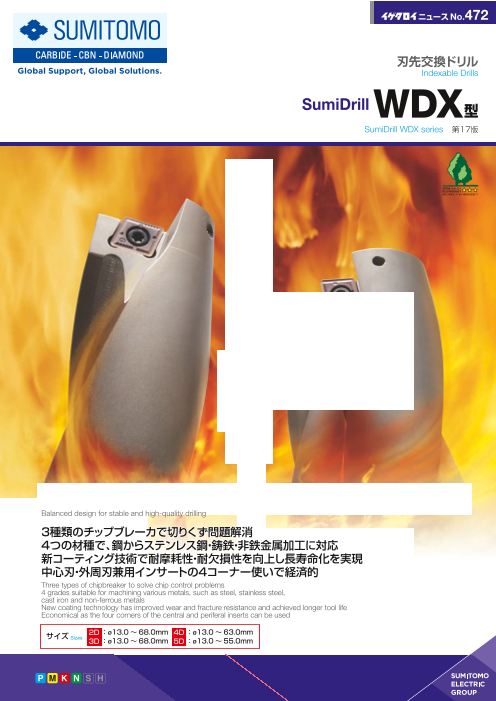
バランス設計で安定した高品位穴あけを実現
Balanced design for stable and high-quality drilling
3種類のチップブレーカで切りくず問題解消
4つの材種で、鋼からステンレス鋼・鋳鉄・非鉄金属加工に対応
新コーティング技術で耐摩耗性・耐欠損性を向上し長寿命化を実現
中心刃・外周刃兼用インサートの4コーナー使いで経済的
Three types of chipbreaker to solve chip control problems
4 grades suitable for machining various metals, such as steel, stainless steel,
cast iron and non-ferrous metals
New coating technology has improved wear and fracture resistance and achieved longer tool life
Economical as the four corners of the central and periferal inserts can be used
サイズ 2D:ø13.0 ~ 68.0mm 4D :ø13.0 ~ 63.0mmSizes 3D :ø13.0 ~ 68.0mm 5D :ø13.0 ~ 55.0mm
Excellent Stability
Page2
切削動画
公開中
VIDEO OF CUTTING
刃先交換ドリルSumiDrill®
Indexable Insert Drills
WDX型
SumiDrill WDX Series
■特長
SumiDrill WDX型は、優れた切削バランスにより、
一般鋼からステンレス鋼・鋳鉄・非鉄金属まで、
被削材を問わず安定した穴あけ加工が可能です。
また、独創的な3種類のチップブレーカを採用し、
切りくず処理の向上と切削抵抗の低減を
実現することにより、剛性の低い加工状況でも
安心して使用することができます。
Characteristics
SumiDrill WDX Type provides so excellent cutting balance that
it enables stable drilling on a wide range of work materials from
general steel to stainless steel.
■シリーズ構成 Series (単位:mm)
加工穴深さ 在庫サイズ
Drilling Depth Available drill diameter in stock
2D用 2D ø13.0~ø68.0
3D用 3D ø13.0~ø68.0
4D用 4D ø13.0~ø63.0
5D用 5D ø13.0~ø55.0
バランス設計で高品位穴あけ ACP100/ACP300/ACK300/DL1500を採用 3種類のブレーカで多用途に対応 旋盤での加工にも対応
Balanced design for high-quality drilling Adopted ACP100, ACP300, ACK300 and DL1500 3 types of chipbreakers to support numerous applications Suitable for use on a lathe
多彩な加工をこなす多機能工具
Versatile Tool to Perform a Variety of Machining Applications
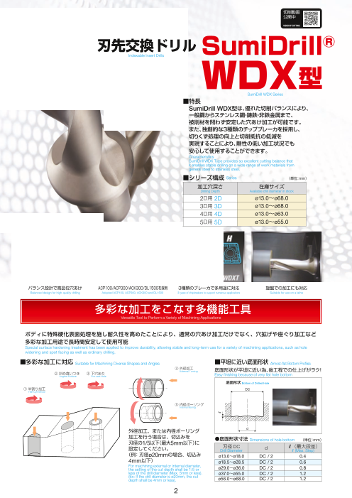
ボディに特殊硬化表面処理を施し耐久性を高めたことにより、通常の穴あけ加工だけでなく、穴拡げや座ぐり加工など
多彩な加工用途で長時間安定して使用可能
Special surface hardening treatment has been applied to improve durability, allowing stable and long-term use for a variety of machining applications, such as hole
widening and spot facing as well as ordinary drilling.
■多彩な加工に対応 Suitable for Machining Diverse Shapes and Angles ■平坦に近い底面形状 Almost-flat Bottom Profiles
④ 外径加工
External Turning 底面形状が平坦に近い為、後工程での仕上げがラク!
② 斜め食いつき ③ 下穴あり Easy finishing because of very flat hole bottom
Angled Surface Pre-cast Hole
底面形状 Bottom of Drilled Hole
① 半割り加工 DC
Half Cylindrical
⑤ 内径ボーリング
Internal Boring
外径加工、または内径ボーリング d
加工を行う場合は、切込みを ●底面形状寸法 Dimensions of hole bottom (単位:mm)
刃径の1/5以下(最大5mm以下)に
設定してください。 刃径 DC d L(最大段差)Drill Diameter L (Max. Step)
(例:刃径ø20mmの場合、切込み ø13.0~ø18.0 DC / 2 0.4
4mm以下) ø18.5~ø28.5 DC / 2 0.6
For machining external or internal diameter,
the setting of the cut depth shall be 1/5 or ø29.0~ø36.0 DC / 2 0.8
less of the drill diameter (Max. 5mm or less). ø37.0~ø55.0 DC / 2 1.2
(Ex: If the drill diameter is ø20mm, the cut
depth shall be 4mm or less). ø56.0~ø68.0 DC / 2 1.2
2
L
Page3
SumiDrill
WDX型
erbly
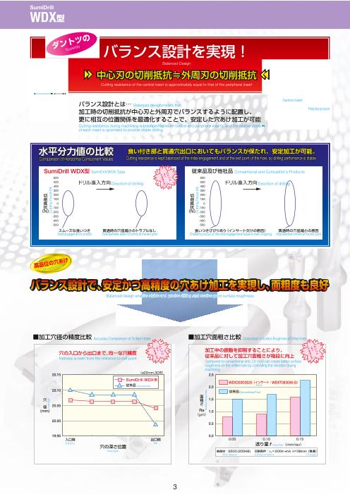
Sup バランス設計を実現!
Balanced Design
中心刃の切削抵抗≒外周刃の切削抵抗
Cutting resistance of the central insert is approximately equal to that of the peripheral insert
Central insert
バランス設計とは… Balanced design means that:
加工時の切削抵抗が中心刃と外周刃でバランスするように配置し、 Peripheral insert
更に相互の位置関係を最適化することで、安定した穴あけ加工が可能
Cutting resistance during machining is balanced between central and peripheral inserts, and the relative position
of each insert is optimised to provide stable drilling.
水平分力値の比較 食い付き部と貫通穴出口においてもバランスが保たれ、安定加工が可能。
Comparison of Horizontal Component Values Cutting resistance is kept balanced at the initial engagement and at the exit point of the hole, so drilling perfomance is stable.
SumiDrill WDX型 SumiDrill WDX Type 従来品及び他社品 Conventional and Competitor's Products
600 600
500 ドリル進入方向 500Direction of drilling ドリル進入方向 Direction of drilling
400 400
300 300
切 200 切 200
削 100 削 100
抵 0 抵 0
抗 -100 抗 -100
(N) -200 (N) -200
-300 -300
-400 -400
-500 -500
スムーズな食いつき 貫通時の穴径縮小のトラブルなし 食いつきびびりあり(インサート欠けの原因) 貫通時の穴径縮小の原因
Initial engagement is smooth Hole diameter does not shrink at the exit point Chattering occurs at the initial engagement(Cause of insert chipping) Hole diameter shrinks at the exit point
高品位の穴
あけ
illing
uality D
r
High-q
Balanced design enables stable and precise drilling and creates good surface roughness
■加工穴径の精度比較 Accuracy Comparison of Drilled Holes ■加工穴面粗さ比較 Comparison of Surface Roughness of Drilled Holes
穴の入口から出口まで、均一な穴精度 加工中の振動を抑制することにより、従来品に対して加工穴面粗さが格段に向上
Flatness is even from the entrance to exit point
Compared to conventional drils, DL1500 can create better surface
roughness on the drilled hole by controlling the vibration during
machining.
(ø20mm,3D用)
WDX200D3S25(インサート:WDXT063006-G)
(Insert:)
Conventional
Conventional Tool
(μm)
Entrance Exit f Feed Rate(mm/rev)
Hole Depth (貫通)
Work Material Cutting Conditions (Through)
3
Hole Size
Cutting Force (N)
Cutting Force (N)
Surface Roughness
Page4
SumiDrill
WDX型
深穴加工用に5Dタイプが登場!(サイズ:ø13.0mm~ ø55.0mm)
5D Type for Deep Holes (Sizes: ø13.0 mm to ø55.0 mm)
大きなクーラント穴
型 用は、専用溝形状 Large coolant hole
L/D=5 専用溝形状
SumiDrill WDX 5D + Special groove shape for L/D=5
クーラント穴サイズUPで、深穴加工においても、
良好な切りくず排出性能を実現しました。
SumiDrill WDX Type for 5D has a special groove shape and
large coolant hole, allowing excellent chip evacuation during
deep hole drilling.
クーラント案内溝 Groove of coolant guide
■性能 Performance
ホルダの特長 Characteristics 断面形状 Cross Section 切削抵抗 Cutting Resistance 加工面(出口) Machined Surface (Exit)
(N) 12,000
WDX260D5S32 スラスト振幅は~ L/D= 4溝設計品より大きいが、 穴奥まで良好な加工面10,000 L/D= 5の深穴加工でも、安定加工可能
L/D=5の専用溝形状
Good machined surface from top to down of the hole
Special groove shape of L/D=5 Amplitude in the thrust direction is larger than that of drill with grooves up to L/D=4, 8,000 but drilling performance of deep hole L/D=5 is stable.
※ 切りくず排出重視設計 6,000
スラスト
溝容量を大きくとった設計で切りくず排出性を向上させ、 Thrust4,000
L/D=5の穴あけにおいても、安定加工が可能。 2,000 水平分力 Horizontal Component of Force
※Groove shape is focused on smooth chip evacuation.
0
SumiDrill WDX Type has large grooves for metal chip 加工深さ L/D=4
-2,000 Depth
evacuation. It also enables stable drilling of L/D=5 holes. 加工深さ L/D=5
-4,000 Depth
比較用工具 (N) 12,000 穴奥で切りくず詰まり発生 穴奥で切りくず詰まりにより加工Chip blockage at bottom of hole
10,000 面悪化(L/D= 5付近)
L/D=4の溝形状 Groove shape of L/D = 4 但し、L/D= 4までは安定加工可能 Poor machined surface due to chip blockage at bottom of hole
8,000 (near L/D = 5)However, stable drilling up to L/D = 4
※ ドリル本体剛性重視設計 6,000
ドリル本体の剛性を上げる溝設計で、 4,000
L/D=4までの浅穴加工で、安定加工が可能。 ドリル剛性が高い為、スラスト振幅が小さい2,000 Rigidity of the drill is high, so amplitude in
※ Flute design is focused on greater rigidity of the drill. the thrust direction is small
0
Therefore, it provides stable drilling for shallow holes of up to
L/D=4. -2,000 加工深さ L/D=4Depth
加工深さ L/D=5
-4,000 Depth
被削材 Work Material: SUS304 インサート Insert: WDXT073506-G
切削条件 Cutting Conditions: vc=150m/min f =0.05mm/rev H=130mm( 貫通 Through) Wet
SumiDrill WDX型 他社品
Hole Size Hole Size
加工面、加工穴径 SumiDrill WDX type Comp.
共に良好!
Excellent finish of machined
surface and hole
Entrance Base Entrance Base
被削材 Work material :機械部品 Machine componen(t SCM415)
使用工具 Tool :WDX200D5S25
インサート Insert :WDXT063006-G(ACP300)
切削条件 Cutting conditions :vc=185m/min f =0.12mm/rev H =87mm 貫通 Through Wet
・加工面良好!! Good machined surface ・ 加工穴径の安定!! Size of hole diameter is stable
SumiDrill WDX型 他社品 Comp.
SumiDrill WDX type SumiDrill WDX型
コーナー欠け、 SumiDrill WDX type
正常摩耗 すくい面摩耗
Normal wear Corner chipping, 正常摩耗
rake face wear Normal wear
ø1200
他社品
Comp.
コーナー欠け
Corner chipping
54-ø33
被削材 Work material :トラックリンク Tractor link(s 35MnBM)
使用工具 Tool :WDX205D5S25
インサート : ( ) 被削材 Work material :風力発電向けベアリング Bearing for wind power generatio(n
42CrMo)
Insert WDXT063006-G ACP300
切削条件 使用工具 Tool :
WDX330D5S40
Cutting conditions: vc=100m/min f =0.11mm/rev H =60mm インサート Insert :WDXT094008-L(ACP300)
貫通 Through Wet 切削条件 Cutting conditions: vc=146m/min f =0.10mm/rev H =158mm
・L/D=5においても安定加工を実現!! 貫通 Through Wet
・インサート欠け、摩耗が抑制され、寿命が安定!! ・インサート欠けによるワーク不良トラブル解消!!
・Stable drilling even at L/D = 5.
・Insert chipping and wear have been reduced and tool life has been stabilized. ・There are fewer defective workpieces caused by insert chipping.
4
158
Page5
SumiDrill
WDX型用インサート WDXTシリーズ
耐摩耗性に優れたCVD材種ACP100で高速加工での長寿命化を実現!
Excellent wear resistance and longer tool life in high speed cutting have been achieved by ACP100
「スーパーFFコート」技術により優れた耐摩耗性を示しながら、他材種と同様に中心刃に適用可能なため、外周刃と中心刃で
インサートを使い分ける必要なく、全4コーナを効率的に使用可能。
Not only do WDXT Series inserts offer superior wear resistance thanks to the new Super FF Coat coating technology, they can also be used as central inserts just like other
grades, so there is no need to differentiate between peripheral and central inserts, and all four corners can be used efficiently.
■コーティングの特長 Feature of coating
C スーパーFFコート( CVD:化学蒸着法(Chemical Vapor Deposition)) ACP100
Super FF Coat
膜の特長 Characteristics of Coating Layer
当社独自の CVD プロセス「スーパーFFコート」技術による
膜硬度: 30%アップ
スーパーFFコート 表面粗さ: %低減 結晶粒子の超微細化と、コーティング膜中応力制御技術により、 50
Super FF Coat Coating hardness アルミナ
30% increase. 優れた耐摩耗性と高い信頼性を両立
T 50 AluminaCoating surface roughness
i 50% reduction. Our unique new CVD process, Super FF Coat technology, produces ultra-flat
C boundary faces between coating layers and super ultra-fine coating particles to
N
膜 40 従来コーティング achieve higher reliability and longer tool life.
硬 Conventional coating
度
30 TiCN
(GPa)
20
基材
0.05 0.10 0.15 0.20 Substrate
TiCN表面粗さ Ra(μm) 膜断面
TiCN Surface Roughness Ra (μm) Cross Section of Coating
P NEWスーパーZXコート/スーパーZXコート( PVD : 物理蒸着法(Physical Vapor Deposition))ACP300 ACK300NEW Super ZX Coat / Super ZX Coat
膜の特長 Characteristics of Coating Layer
当社独自の薄膜コーティング技術と先進のナノテクノロジーを
New スーパーZXコート
60 New Super ZX Coat 駆使し、一層の厚みがナノメートル台(1ナノメートルは
10億分の1メートル)の超薄膜を交互に数千層積層させた
スーパーZXコート50
膜 Super ZX Coat 超多層膜「NewスーパーZXコート」を採用
硬 積層周期Laminating
度 Utilising our proprietary thin layer coating technology and advanced 40 ZXコート Cycle to
ZX Coat ~10nm
nanotechnology, Sumitomo Electric Hardmetal has developed NEW Super
ZX Coat and Super ZX Coat, coatings that consist of approximately 1,000
( ) TiCN alternating, nanometre-level-thin (1 nanometre = 1 billionth of a metre) layers.GPa 30
TiAIN
20 TiN
600 800 1,000 1,200 10nm
酸化開始温度(°C) 膜断面(TEM像)
Starting Temperature For Oxidization (°C) Cross Section of Coating (TEM Image)
非鉄金属加工用材種オーロラコートDL1500
Aurora coating material for machining non-ferrous metal DL1500
非鉄金属加工用材種DL1500は従来品に対し、耐溶着性能が格段に向上しました。
アルミニウム合金はもちろん、銅合金などの穴あけ加工に最適です。
Compared to previous materials, DL1500 provides superior adhesion resistance. Therefore, it is ideal for drilling holes on copper alloy as well as aluminum alloy.
■使用実例 Application Examples
DL1500 ACK300 被削材 :ADC52
Work Material
す 使用工具:WDX250D3S25(DL1500,G型)
く 溶着 Tool
い 切削条件:vc=150m/min(n=1,911min-1)
外 面 Cutting Conditions f=0.1mm/rev
周
刃 H=50mm 貫通 Through Wet
逃
げ 溶着
面
す
く 溶着
い
中 面
心
刃
逃
げ
面 溶着
※溶着 : Adhesion
5
Central Insert Peripheral Insert
Coating Hardness
TiCN Coating Hardness
Flank Rake Face Flank Rake Face
Page6
SumiDrill
WDX型用インサート WDXTシリーズ
3種類のブレーカで、幅広い被削材、用途に対応
Three types of chipbreakers to support a wide range of work materials and applications
ブレーカ中央部に形成された『切りくず制御溝』の効果により切りくず流出方向の制御を可能にし、
3種類の用途別ブレーカを使い分けることでさまざまな被削材、条件下において、切りくずトラブルを激減
"Chip controlling groove" created in the center part of the breaker controls the direction of chip evacuation. Chip problems with different work materials under various
conditions can be reduced drastically by using these three chip breakers selectively depending on the usage.
■ブレーカの種類 Chipbreaker Types
L 低速送り・型 切りくず処理用 G型 汎 用 刃先強化型General Purpose H型 Strong Edge Type
Low feed, chip management type
断面形状 断面形状 断面形状
Cross Section Cross Section Cross Section
●すくい角 Rake Angle
大 小
●ブレーカ幅 Chipbreaker Width
狭 広
■4コーナー使いインサートで経済的 Economical by the use of four corners
中心刃、外周刃兼用インサート採用で、
中心刃2コーナー、外周刃2コーナーの
計4コーナーが使用可能 中
刃 心Inserts have four cutting edges in total: two central cutting 周 刃
edges and peripheral cutting edges. 外 中心刃
CVDコーティング材種であるACP100も対応!
ACP100, CVD coated grade is adopted. 中心刃 刃
※中 心刃: 外
周
Central cutting edge
外周刃:Peripheral cutting edge
外周刃
インサート選択ガイド―いろいろ選べるWDX型用インサートシリーズ
Insert Selection ̶ WDX Type Insert Series Offers Wide Selection
4 種類の材種 種類のブレーカ 種類の組合せが可能に!Four material grades 3 Three types of chip breakers 10 Ten possible combinations
材 種
Grade ACP100 ACP300 ACK300 DL1500
被削材 ACP100 ACP300 ACK300 DL1500Work Material 高
P 鋼( 高速加工用) H型 P K P M P K
Steel (High-Speed Machining) ↑
P 鋼( 一般加工用) G型 L型 L型 L型
Steel (General Machining) 刃
先 P K P M P K N
M ステンレス鋼 強 L型
Stainless Steel 度 G型 G型 G型 G型
K 鋳鉄( 高速加工用)
Cast Iron (High-Speed Machining) 0.05 0.10 0.15 0.20 0.25 P K P K
K 鋳鉄( 一般加工用) 送り量(mm/rev)Feed Rate
Cast Iron (General Machining) H型 H型 H型
N 非鉄金属
Non-Ferrous Metal
6
Cutting Edge Strength High
Page7
SumiDrill
WDX型用インサート WDXTシリーズ
汎用
General Purpose
低速送り・
第 切りくず処理用 刃先強化型Low Feed, Chip Management Type G型 ACP100 Strong Edge Type
・一般鋼・合金鋼の加工で、逃げ面摩耗発生が
2 L 大きい場合に型ACP300 For application where sereve flank wear may be caused by machining general alloy or alloy steal H型ACP300
推 ・SS400,SCM415,SCM420等の加工に ・斜め食いつき等による断続 (入口・貫通 )For machining SS400, SCM415, SCM420, etc. 加工の場合、送りは断続部で下げる
奨 ・切りくず処理に問題がある場合は、 高速低送りを (f =0.05mm/rev 程度 ) 推奨します 低速送り・ For interrupted machining (at entrance/exit) of angled surfaces, 切りくず処理用
In case of chip control problem, high speed with low feed reduce the feed rate (to approximately f= 0.05mm/rev) at each interruption.L Low Feed, Chip Management TypeP rate is recommended. 型 ACP100 ・高硬度材 (熱処理 )の加工による、・切りくず焼けにより振動が発生する場合は、 刃先強度不足の場合に
送りを下げる Ideal to use when the cutting edge is weakened due to ・送り条件が低い場合に machining hardened material (heat treatment)
In case of vibration due to burnt chips, reduce the feed rate. For low feed rate conditions
切りくず処理改善 初期チッピング対応
(低炭素鋼など) 耐摩耗性不足 (断続・高硬度など)
Improvement of chip control Lack of wear resistance Reduction of initial chipping
(low-carbon steel, etc.) (caused by interrupted machining, machining hard material, etc.)
一般鋼・合金鋼 /ステンレス鋼加工用には
第
1 汎用 ACP300For machining general steel, alloy steel or stainless steelGeneral Purpose
推 鋳鉄加工用には
奨 G ACK300For machining cast iron型 非鉄金属加工用にはP M
K N DL1500For machining non-ferrous metals
耐摩耗性不足 初期チッピング対応
切りくず処理改善 (高速加工) (断続・高送り)
Improvement of chip control Lack of wear resistance Reduction of initial chipping
(High speed machining) (interrupted/high feed rate machining, etc.)
低速送り・
切りくず処理用 汎用 刃先強化型
Low feed, chip management type General Purpose Strong Edge Type
L型ACP300 G型 ACP100 H型ACK300
・設備上、切削速度・送りが上げられず、 ・鋳鉄加工で逃げ面摩耗が大きい場合に ・鋼加工同様に、斜め食いつき等による
切りくず処理が問題になる場合に For applications where severe flank wear may be 断続切削の場合に
L Type ACP300 is ideal to solve chip evacuation problem caused by machining cast iron. Similar to steel machining, H Type ACK300 is ideal for
caused by low cutting speed and low feed rate due to interrupted machining on angled surfaces.
facility reasons.
・高速・低~中送りで摩耗を抑えたい場合に ・高送り加工により、刃先強度不足の場合に
M K Ideal for reducing wear at high speeds with low to With strong edges, it is ideal for machining workpieces medium feed rates. at high feed rate.
*200HB以上の高硬度鋼加工及び鋼高速加工の場合、ACP100が第1推奨となります。
*New ACP100 is recommended the first in the cutting of high hardness steel (≧200HB) and the high speed cutting of steel.
7
2nd Recommendation 1st Recommendation 2nd Recommendation
Page8
SumiDrill
WDX型 2D用(内部給油式) 炭素・合金鋼 炭素・合金鋼 高硬度鋼 ステン ダクタイル アルミニウム~0.28% 0.29%~ ~45 レス鋼 鋳鉄 鋳鉄 HRC 合金
オーロラ 油穴付き 刃先交換
コート コート コート ※h7公差は総合カタログをご覧ください。
Fig 1 Fig 2 Fig 3
LUX LUX LUX
LPR LS LPR LS LPR LS
OAL OAL OAL
■ホルダ 刃径 ø13.0~ 45.0mm 寸法(mm) ■ホルダ 刃径 ø46.0~ 68.0mm 寸法(mm)
Holder Diameter Dimensions Holder Diameter Dimensions
刃径 在庫 型番 首下長 突出長 全長 シャンク ボス シャンク径 半径方向適用 刃径 在庫 型番 首下長 突出長 全長 シャンク ボス シャンク径 半径方向適用Diameter Length Over hang Length Shank Flange Diameter オフセット量 インサート Fig Diameter Length Over hang Length Shank Flange Diameter
オフセット量
(最大) インサート FigDC Stock Cat. No. LUX LPR OAL LS DCSFMS DCON DC Stock Cat. No. (最大) Offset Insert LUX LPR OAL LS DCSFMS DCON Offset Insert
13.0 ● WDX 130D2S20 29 44 88 0.35 1 46.0 ● WDX 460D2S40 97 127 197 1.50 2
13.5 ● WDX 135D2S20 30 45 89 0.30 1 47.0 ● WDX 470D2S40 99 129 199 1.40 2
14.0 ● WDX 140D2S20 31 46 90 44 28.0 20 0.25 WDXT042004 1 48.0 ● WDX 480D2S40 101 131 201 1.30 2
14.5 ● WDX 145D2S20 32 47 91 0.20 1 49.0 ● WDX 490D2S40 49.5103 133 203 1.20 2
15.0 ● WDX 150D2S20 33 48 92 0.15 1 50.0 ● WDX 500D2S40 105 135 205 1.10 WDXT 2
15.5 ● WDX 155D2S20 70 4034 49 93 1 51.0 ● WDX 510D2S40 107 137 207 1.00 156012 3
● WDX 160D2S20 0.4016.0 35 50 94 1 52.0 ● WDX 520D2S40 109 139 209 50.5 0.90 3
16.5 ● WDX 165D2S20 44 30.0 2036 51 95 0.35 WDXT 1 53.0 ● WDX 530D2S40 111 141 211 51.5 0.80 3
17.0 ● WDX 170D2S20 37 52 96 0.30 052504 1 54.0 ● WDX 540D2S40 113 143 213 52.5 0.60 3
17.5 ● WDX 175D2S25 38 53 109 0.25 1 55.0 ● WDX 550D2S40 115 145 215 53.5 0.50 3
18.0 ● WDX 180D2S25 56 32.0 2539 54 110 0.20 1 56.0 ● WDX 560D2S40 120 152 222 54.0 2.00 3
18.5 ● WDX 185D2S25 40 55 111 0.50 1 57.0 ● WDX 570D2S40 122 154 224 55.0 1.80 3
19.0 ● WDX 190D2S25 41 56 112 0.45 1 58.0 ● WDX 580D2S40 124 156 226 56.0 1.70 3
19.5 ● WDX 195D2S25 42 57 113 0.40 1 59.0 ● WDX 590D2S40 126 158 228 57.0 1.60 3
20.0 ● WDX 200D2S25 43 58 114 1 60.0 ● WDX 600D2S40 128 160 230 58.0 1.50 3
0.30
20.5 ● WDX 205D2S25 44 59 115 56 33.0 25 WDXT063006 1 61.0 ● WDX 610D2S40 130 162 232 59.0 1.40 3
21.0 ● WDX 210D2S25 45 60 116 0.20 1 62.0 ● WDX 620D2S40 132 164 234 70 60.0 40 1.30 WDXT
● WDX 215D2S25 ● WDX 630D2S40 186012
3
21.5 46 61 117 0.15 1 63.0 134 166 236 61.0 1.20 3
22.0 ● WDX 220D2S25 47 62 118 0.10 1 64.0 ● WDX 640D2S40 136 168 238 62.0 1.00 3
22.5 ● WDX 225D2S25 48 63 119 0.05 1 65.0 ● WDX 650D2S40 138 170 240 63.0 0.90 3
23.0 ● WDX 230D2S25 49 67 123 1 66.0 ● WDX 660D2S40 140 172 242 64.0 0.70 3
23.5 ● WDX 235D2S25 0.7050 68 124 1 67.0 ● WDX 670D2S40 142 174 244 65.0 0.60 3
24.0 ● WDX 240D2S25 51 69 125 56 37.0 25 0.60 1 68.0 ● WDX 680D2S40 144 176 246 66.0 0.50 3
24.5 ● WDX 245D2S25 52 70 126 1
0.50
25.0 ● WDX 250D2S25 53 71 127 1
25.5 ● WDX 255D2S32 54 74 134 0.45 WDXT 2 ■部品 Spare Parts
26.0 ● WDX 260D2S32 55 75 135 0.40 073506 2 皿ねじ レンチ レンチ
26.5 ● WDX 265D2S32 56 76 136 0.35 2 Screw Wrench Wrench
27.0 ● WDX 270D2S32 57 77 137 60 41.0 32 0.25 2 適用ホルダ
27.5 ● WDX 275D2S32 58 78 138 0.20 2 Applicable Holder N m
28.0 ● WDX 280D2S32 59 79 139 0.15 2
28.5 ● WDX 285D2S32 60 80 140 0.10 2 WDX130D2S20~WDX150D2S20 BFTX01604N 0.3 TRX06 -
29.0 ● WDX 290D2S32 62 83 143 1.00 2
50.0 WDX155D2S20~WDX180D2S25 BFTX0204N 0.5 TRX06 -
29.5 ● WDX 295D2S32 63 84 144 0.95 2 WDX185D2S25~WDX225D2S25 BFTY02206 1.0 - TRD07
30.0* ● WDX 300D2S32 64 88 148 60 32 0.90 2 WDX230D2S25~WDX285D2S32 BFTX02506N 1.5 - TRD08
31.0* ● WDX 310D2S32 66 90 150 54.0 0.80 2 WDX290D2S32~WDX360D2S40 BFTX03584 3.5 - TRD15
32.0* ● WDX 320D2S32 68 92 152 0.70 2 WDX370D2S40~WDX450D2S40 BFTX0511N 5.0 - TRD20
30.0* ● WDX 300D2S40 64 88 158 0.90 WDXT 2 WDX460D2S40~WDX680D2S40 BFTX0615N 5.0 - TRD25
31.0* ● WDX 310D2S40 66 90 160 0.80 094008 2
32.0* ● WDX 320D2S40 68 92 162 0.70 2
33.0 ● WDX 330D2S40 70 94 164 70 54.0 40 0.55 2 ■型番の呼び方 Identification Code
34.0 ● WDX 340D2S40 72 96 166 0.45 2
35.0 ● WDX 350D2S40 74 98 168 0.35 2 WDX 200 D2 S25
36.0 ● WDX 360D2S40 76 100 170 0.20 2 刃径 DC シャンク径 DCON
37.0 ● WDX 370D2S40 79 109 179 2 Dia. Shank Dia.
(ø20.0) (ø25.0)
38.0 ● WDX 380D2S40 1.00 ドリル刃長 L/D81 111 181 2 Flute Length
39.0 ● WDX 390D2S40 83 113 183 0.90 2 (2D)
40.0 ● WDX 400D2S40 85 115 185 0.80 2
41.0 ● WDX 410D2S40 87 117 187 70 49.5 40 0.70 WDXT 2
42.0 ● WDX 420D2S40 12501289 119 189 0.60 2 ■ 加工公差の目安
Range of machining tolerance
43.0 ● WDX 430D2S40 91 121 191 2 (mm)
0.50
44.0 ● WDX 440D2S40 93 123 193 2 DC 加工公差の目安
45.0 ● WDX 450D2S40 95 125 195 0.40 2 ø22.5以下 0 ~ +0.15
*刃径 、 、 はシャンク径 と を在庫しています。 ø22.5をこえ ø36.0以下 -0.05~ +0.25ø30 ø31 ø32 ø32 ø40
*Diameters ø30, ø31, ø32 are in stock with shank diameters of ø32 and ø40. ø36.0をこえ -0.05~ +0.30
半径方向オフセット量 P16 上記数値は目安であり、切削条件、機械剛性やクランプ状態、
被削材等で変動する可能性があります。
Radial Offset Amount The machining tolerance above are a guide.
D印:標準在庫品
: mark: Standard stock item
8
DC
DCSFMS
DCON h7
DC
DCSFMS
DCON h7
DC
DCSFMS
DCON h7
Page9
SumiDrill
WDX型 2D用(内部給油式)
■インサート Insert 寸法 Dimensions(mm)
材種分類 コーティング
Dimensions Coated Carbide
適用 高速・軽切削
P
High-speed/Light K N
加工 汎用切削 General-purpose
Process粗切削 Roughing K
幅 厚さ コーナー 型番 Length Length 半径 適用ホルダ
Cat. No. Nose Radius
Fig
W1 W1 Applicable HolderRE Fig 1
WDXT 042004-L ● ● ● 1 W1 RE
WDXT 042004-G ● ● ●● 4.2 2.0 0.4 WDX130D2S20~WDX150D2S20 2
WDXT 042004-H ● ● ● L 型3
WDXT 052504-L ● ● ● 1
WDXT 052504-G ● ● ●● 5.0 2.5 0.4 WDX155D2S20~WDX180D2S25 2 RE
WDXT 052504-H ● ● ● 3 L型:低速送り・切りくず処理用
WDXT 063006-L ● ● ● 1 L Type: For low feed with chip control
WDXT 063006-G ● ● ●● 6.0 3.0 0.6 WDX185D2S25~WDX225D2S25 2 Fig 2
WDXT 063006-H ● ● ● 3 W1 RE
WDXT 073506-L ● ● ● 1
WDXT 073506-G ● ● ●● 7.5 3.5 0.6 WDX230D2S25~WDX285D2S32 2 G型
WDXT 073506-H ● ● ● 3
WDXT 094008-L ● ● ● 1 RE
WDXT 094008-G ● ● ●● 9.6 4.0 0.8 WDX290D2S32~WDX360D2S40 2 G型:汎用
WDXT 094008-H ● ● ● 3 G Type: General-purpose
WDXT 125012-L ● ● ● 1 Fig 3
WDXT 125012-G ● ● ●● 12.4 5.0 1.2 WDX370D2S40~WDX450D2S40 2 W1 RE S
WDXT 125012-H ● ● ● 3
WDXT 156012-L ● ● ● 1 H型
WDXT 156012-G ● ● ●● 15.2 6.0 1.2 WDX460D2S40~WDX550D2S40 2
WDXT 156012-H ● ● ● 3 RE
WDXT 186012-L ● ● ● 1 H型:刃先強化型
WDXT 186012-G ● ● ● 18.0 6.0 1.2 WDX560D2S40~WDX680D2S40 2 H Type: Strong edge
WDXT 186012-H ● ● ● 3
■型番の呼び方 Identification Code
WDXT 06 30 06 -G
対辺寸法 厚さ×10 ブレーカ種類
Width across Flats Thickness Breaker Type
(6.0) (3.0)
コーナー半径×10
Nose Radius
(0.6)
■推奨切削条件( 2D用) Recommended Cutting Conditions (for 2D)
ワーク硬度 推奨 推奨 v 切削速度 f 送り量( mm/rev) 〈 下限値-推奨値-上限値〉
被削材 Workpiece ブレーカ インサート材種 c feed rate Min. - Optimum - Max.Cutting Speed
Work Material Hardness Recommended Recommended
HB (m/min)Chipbreaker Insert Grade ø13.0~ø18.0 ø18.5~ø29.0 ø29.5~ø36.0 ø37.0~ø55.0 ø56.0~ø63.0
鋼 , 炭素鋼 SS400 125 G ACP300 120-180-240 0.05-0.08-0.10 0.05-0.08-0.10 0.05-0.08-0.11 0.05-0.08-0.12 0.06-0.09-0.13
Steel, Carbon Steel
S15C 125 L ACP300 130-170-220 0.04-0.08-0.12 0.04-0.08-0.12 0.04-0.08-0.13 0.05-0.10-0.15 0.06-0.11-0.17
S45C 190 G ACP300 100-150-200 0.08-0.13-0.24 0.08-0.13-0.24 0.08-0.14-0.26 0.09-0.16-0.29 0.10-0.17-0.32
S45C 焼入れ Hardened 250 G ACP100 100-170-240 0.05-0.09-0.14 0.05-0.09-0.14 0.05-0.09-0.14 0.05-0.10-0.17 0.06-0.11-0.18
S75C 270 G ACP100 120-180-240 0.06-0.10-0.17 0.06-0.10-0.17 0.06-0.10-0.17 0.07-0.12-0.19 0.08-0.13-0.21
S75C 焼入れ Hardened 300 G ACP100 85-150-210 0.05-0.09-0.14 0.05-0.09-0.14 0.05-0.09-0.14 0.05-0.10-0.15 0.06-0.11-0.17
P 低合金鋼 SCM,SNCM 180 L ACP300 100-140-180 0.05-0.08-0.14 0.05-0.08-0.14 0.05-0.08-0.16 0.06-0.09-0.17 0.07-0.10-0.19
Low-alloy Steel
SCM,SNCM 焼入れ Hardened 275 G ACP100 100-170-240 0.06-0.10-0.14 0.06-0.10-0.14 0.06-0.10-0.14 0.07-0.11-0.16 0.08-0.11-0.17
SCM,SNCM 焼入れ Hardened 300 G ACP100 90-150-210 0.06-0.10-0.14 0.06-0.10-0.14 0.06-0.10-0.14 0.07-0.11-0.16 0.08-0.11-0.17
SCM,SNCM 焼入れ Hardened 350 G ACP100 75-120-165 0.06-0.10-0.14 0.06-0.10-0.14 0.06-0.10-0.14 0.07-0.11-0.16 0.08-0.11-0.17
高合金鋼 SKD,SKT,SKH 200 G ACP100 120-180-240 0.08-0.12-0.17 0.08-0.12-0.17 0.08-0.12-0.18 0.09-0.12-0.21 0.10-0.13-0.22
High-alloy Steel
SKD,SKT,SKH 焼入れ Hardened 325 G ACP100 100-140-180 0.06-0.10-0.15 0.06-0.10-0.15 0.06-0.11-0.15 0.07-0.11-0.16 0.08-0.11-0.17
ステンレス鋼 SUS403他 (マルテンサイト/フェライト) 200 G ACP300 100-140-180 0.06-0.11-0.18 0.06-0.11-0.18 0.06-0.12-0.19 0.07-0.13-0.22 0.08-0.14-0.24
Stainless Steel Others (Martensitic/Ferritic)
M SUS403他 マルテンサイト系(焼入れ) 240 G ACP300 90-120-150 0.06-0.11-0.18 0.06-0.11-0.18 0.06-0.12-0.19 0.07-0.13-0.22 0.08-0.14-0.24
Others Martensitic (hardened)
SUS304,SUS316 オーステナイト系 180 G ACP300 100-140-180 0.06-0.11-0.18 0.06-0.11-0.18 0.06-0.12-0.19 0.07-0.13-0.22 0.08-0.14-0.24
Austenitic
鋳鉄 Cast Iron H ACK300 120-160-200 0.09-0.20-0.32 0.10-0.22-0.36 0.11-0.24-0.39 0.12-0.26-0.44 0.13-0.29-0.48
K
ダクタイル鋳鉄 Ductile Cast Iron H ACK300 90-120-150 0.09-0.20-0.32 0.10-0.22-0.36 0.11-0.24-0.39 0.12-0.26-0.44 0.13-0.29-0.48
S 難削材(耐熱合金、超合金、チタン合金 etc.) 200 G ACP300 25-50-70 0.06-0.11-0.18 0.06-0.11-0.18 0.06-0.12-0.19 0.07-0.13-0.22 0.08-0.14-0.24
Exotic Alloy (Heat-Resistant Alloy, Super Alloy, Titanium Alloy, etc.)
アルミニウム合金 Aluminum Alloy G DL1500 200-260-320 0.06-0.11-0.17 0.06-0.11-0.17 0.06-0.12-0.18 0.07-0.13-0.20 0.08-0.14-0.22
N
銅合金 Copper Alloy G DL1500 180-230-280 0.06-0.11-0.17 0.06-0.11-0.17 0.06-0.12-0.18 0.07-0.13-0.20 0.08-0.14-0.22
P種、K種で第一推奨インサート材種がACP300、ACK300の場合の第二推奨インサート材種は、ACP100になります。
この時の推奨切削条件は、切削速度vcは上表の130%、送り量f は75%を目安としてください。
For the P and K grades for which ACP300 and ACK300 inserts are the first recommendation, ACP100 inserts are the second recommendation.
In this case, it is recommended to set the cutting speed (vc) to 130% and the feed rate (f) to 75% of the figures in the table above.
D印:標準在庫品 無印:受注生産品
: mark: Standard stock item, no mark: made to order item
9
ACP100
ACP300
ACK300
DL1500
Page10
SumiDrill
WDX型 3D用(内部給油式) 炭素・合金鋼 炭素・合金鋼 高硬度鋼 ステン 鋳鉄 ダクタイル アルミニウム~0.28% 0.29%~ ~45HRC レス鋼 鋳鉄 合金
オーロラ 油穴付き
コート コート コート 刃先交換 ※h7公差は総合カタログをご覧ください。
■ホルダ 刃径 ø13.0~ 45.0mm 寸法(mm) ■ホルダ 刃径 ø46.0~ 68.0mm 寸法(mm)
Holder Diameter Dimensions Holder Diameter Dimensions
刃径 首下長 突出長 全長 シャンク ボス シャンク径 半径方向適用 刃径 首下長 突出長 全長 シャンク ボス シャンク径 半径方向適用
Diameter 在庫 型番 Length Over hang Length Shank Flange Diameter オフセット量 インサート Fig Diameter 在庫 型番 Length Over hang Length Shank Flange Diameter オフセット量 インサート Fig
DC Stock Cat. No. LUX LPR OAL LS DCSFMS DCON (最大) Stock Cat. No.Offset Insert DC LUX LPR OAL LS DCSFMS DCON
(最大)
Offset Insert
13.0 ● WDX 130D3S20 42.0 57.0 101.0 0.35 1 46.0 ● WDX 460D3S40 143.0 173.0 243.0 1.50 2
13.5 ● WDX 135D3S20 43.5 58.5 102.5 0.30 1 47.0 ● WDX 470D3S40 146.0 176.0 246.0 1.40 2
14.0 ● WDX 140D3S20 45.0 60.0 104.0 44 28.0 20 0.25 WDXT 1 48.0 ● WDX 480D3S40 149.0 179.0 249.0 1.30 2
14.5 ● WDX 145D3S20 042004 ● WDX 490D3S40 49.546.5 61.5 105.5 0.20 1 49.0 152.0 182.0 252.0 1.20 2
15.0 ● WDX 150D3S20 48.0 63.0 107.0 0.15 1 50.0 ● WDX 500D3S40 155.0 185.0 255.0 1.10 WDXT 2
15.5 ● WDX 155D3S20 70 4049.5 64.5 108.5 1 51.0 ● WDX 510D3S40 158.0 188.0 258.0 1.00 156012 3
● WDX 160D3S20 0.4016.0 51.0 66.0 110.0 1 52.0 ● WDX 520D3S40 161.0 191.0 261.0 50.5 0.90 3
16.5 ● WDX 165D3S20 44 30.0 2052.5 67.5 111.5 0.35 WDXT 1 53.0 ● WDX 530D3S40 164.0 194.0 264.0 51.5 0.80 3
17.0 ● WDX 170D3S20 54.0 69.0 113.0 0.30 052504 1 54.0 ● WDX 540D3S40 167.0 197.0 267.0 52.5 0.60 3
17.5 ● WDX 175D3S25 55.5 70.5 126.5 0.25 1 55.0 ● WDX 550D3S40 170.0 200.0 270.0 53.5 0.50 3
56 32.0 25
18.0 ● WDX 180D3S25 57.0 72.0 128.0 0.20 1 56.0 ● WDX 560D3S40 176.0 208.0 278.0 54.0 2.00 3
18.5 ● WDX 185D3S25 58.5 73.5 129.5 0.50 1 57.0 ● WDX 570D3S40 179.0 211.0 281.0 55.0 1.80 3
19.0 ● WDX 190D3S25 60.0 75.0 131.0 0.45 1 58.0 ● WDX 580D3S40 182.0 214.0 284.0 56.0 1.70 3
19.5 ● WDX 195D3S25 61.5 76.5 132.5 0.40 1 59.0 ● WDX 590D3S40 185.0 217.0 287.0 57.0 1.60 3
20.0 ● WDX 200D3S25 63.0 78.0 134.0 1 60.0 ● WDX 600D3S40 188.0 220.0 290.0 58.0 1.50 3
20.5 ● WDX 205D3S25 0.3064.5 79.5 135.5 56 33.0 25 WDXT063006 1 61.0 ● WDX 610D3S40 191.0 223.0 293.0 59.0 1.40 3
21.0 ● WDX 210D3S25 66.0 81.0 137.0 0.20 1 62.0 ● WDX 620D3S40 194.0 226.0 296.0 70 60.0 40 1.30 WDXT 3
21.5 ● WDX 215D3S25 18601267.5 82.5 138.5 0.15 1 63.0 ● WDX 630D3S40 197.0 229.0 299.0 61.0 1.20 3
22.0 ● WDX 220D3S25 69.0 84.0 140.0 0.10 1 64.0 ● WDX 640D3S40 200.0 232.0 302.0 62.0 1.00 3
22.5 ● WDX 225D3S25 70.5 85.5 141.5 0.05 1 65.0 ● WDX 650D3S40 203.0 235.0 305.0 63.0 0.90 3
23.0 ● WDX 230D3S25 72.0 90.0 146.0 1 66.0 ● WDX 660D3S40 206.0 238.0 308.0 64.0 0.70 3
23.5 ● WDX 235D3S25 0.7073.5 91.5 147.5 1 67.0 ● WDX 670D3S40 209.0 241.0 311.0 65.0 0.60 3
24.0 ● WDX 240D3S25 75.0 93.0 149.0 56 37.0 25 0.60 1 68.0 ● WDX 680D3S40 212.0 244.0 314.0 66.0 0.50 3
24.5 ● WDX 245D3S25 76.5 94.5 150.5 1
25.0 ● WDX 250D3S25 0.5078.0 96.0 152.0 1
25.5 ● WDX 255D3S32 79.5 99.5 159.5 0.45 WDXT 2 ■部品 Spare Parts
26.0 ● WDX 260D3S32 81.0 101.0 161.0 0.40 073506 2 皿ねじ レンチ レンチ
26.5 ● WDX 265D3S32 82.5 102.5 162.5 0.35 2 Screw Wrench Wrench
27.0 ● WDX 270D3S32 84.0 104.0 164.0 60 41.0 32 0.25 2 適用ホルダ
27.5 ● WDX 275D3S32 85.5 105.5 165.5 0.20 2 Applicable Holder N m
28.0 ● WDX 280D3S32 87.0 107.0 167.0 0.15 2
28.5 ● WDX 285D3S32 88.5 108.5 168.5 0.10 2 WDX130D3S20~WDX150D3S20 BFTX01604N 0.3 TRX06 -
29.0 ● WDX 290D3S32 91.0 112.0 172.0 1.00 2 WDX155D3S20~WDX180D3S25 BFTX0204N 0.5 TRX06 -
29.5 ● WDX 295D3S32 50.092.5 113.5 173.5 0.95 2 WDX185D3S25~WDX225D3S25 BFTY02206 1.0 - TRD07
30.0* ● WDX 300D3S32 94.0 118.0 178.0 60 32 0.90 2 WDX230D3S25~WDX285D3S32 BFTX02506N 1.5 - TRD08
31.0* ● WDX 310D3S32 97.0 121.0 181.0 54.0 0.80 2 WDX290D3S32~WDX360D3S40 BFTX03584 3.5 - TRD15
32.0* ● WDX 320D3S32 100.0 124.0 184.0 0.70 2 WDX370D3S40~WDX450D3S40 BFTX0511N 5.0 - TRD20
30.0* ● WDX 300D3S40 94.0 118.0 188.0 0.90 WDXT 2 WDX460D3S40~WDX680D3S40 BFTX0615N 5.0 - TRD25
31.0* ● WDX 310D3S40 97.0 121.0 191.0 0.80 094008 2
32.0* ● WDX 320D3S40 100.0 124.0 194.0 0.70 2
33.0 ● WDX 330D3S40 103.0 127.0 197.0 70 54.0 40 0.55 2 ■型番の呼び方 Identification Code
34.0 ● WDX 340D3S40 106.0 130.0 200.0 0.45 2
35.0 ● WDX 350D3S40 109.0 133.0 203.0 0.35 2 WDX 200 D3 S25
36.0 ● WDX 360D3S40 112.0 136.0 206.0 0.20 2 刃径 DC シャンク径 DCON
37.0 ● WDX 370D3S40 116.0 146.0 216.0 2 Dia. Shank Dia.
(ø20.0) (ø25.0)
38.0 ● WDX 380D3S40 1.00 ドリル刃長 L/D119.0 149.0 219.0 2 Flute Length
39.0 ● WDX 390D3S40 122.0 152.0 222.0 0.90 2 (3D)
40.0 ● WDX 400D3S40 125.0 155.0 225.0 0.80 2
41.0 ● WDX 410D3S40 128.0 158.0 228.0 70 49.5 40 0.70 WDXT125012 2
42.0 ● WDX 420D3S40 131.0 161.0 231.0 0.60 2 ■ 加工公差の目安
Range of machining tolerance
43.0 ● WDX 430D3S40 134.0 164.0 234.0 2 (mm)
44.0 ● WDX 440D3S40 0.50137.0 167.0 237.0 2 DC 加工公差の目安
45.0 ● WDX 450D3S40 140.0 170.0 240.0 0.40 2 ø22.5以下 0 ~ +0.20
*刃径ø30、ø31、ø32はシャンク径ø32とø40を在庫しています。 ø22.5
をこえ ø36.0以下 -0.05~ +0.25
*Diameters ø30, ø31, ø32 are in stock with shank diameters of ø32 and ø40. ø36.0をこえ -0.05~ +0.30
半径方向オフセット量 P16 上記数値は目安であり、切削条件、機械剛性やクランプ状態、
被削材等で変動する可能性があります。
Radial Offset Amount The machining tolerance above are a guide.
D印:標準在庫品
: mark: Standard stock item
10
Page11
SumiDrill
WDX型 3D用(内部給油式)
■インサート Insert 寸法 Dimensions(mm)
材種分類 コーティング
Dimensions Coated Carbide
高速・軽切削 P適用 High-speed/Light K N
加工 汎用切削 General-purpose
Process粗切削 Roughing K
コーナー
型番 幅 厚さ Length Length 半径 適用ホルダ
Cat. No. Nose Radius
Fig
W1 W1 Applicable HolderRE Fig 1
WDXT 042004-L ● ● ● 1 W1 RE
WDXT 042004-G ● ● ●● 4.2 2.0 0.4 WDX130D3S20~WDX150D3S20 2
WDXT 042004-H ● ● ● L 型3
WDXT 052504-L ● ● ● 1
WDXT 052504-G ● ● ●● 5.0 2.5 0.4 WDX155D3S20~WDX180D3S25 2 RE
WDXT 052504-H ● ● ● 3 L型:低速送り・切りくず処理用
WDXT 063006-L ● ● ● 1 L Type: For low feed with chip control
WDXT 063006-G ● ● ●● 6.0 3.0 0.6 WDX185D3S25~WDX225D3S25 2 Fig 2
WDXT 063006-H ● ● ● 3 W1 RE
WDXT 073506-L ● ● ● 1
WDXT 073506-G ● ● ●● 7.5 3.5 0.6 WDX230D3S25~WDX285D3S32 2 G型
WDXT 073506-H ● ● ● 3
WDXT 094008-L ● ● ● 1 RE
WDXT 094008-G ● ● ●● 9.6 4.0 0.8 WDX290D3S32~WDX360D3S40 2 G型:汎用
WDXT 094008-H ● ● ● 3 G Type: General-purpose
WDXT 125012-L ● ● ● 1 Fig 3
WDXT 125012-G ● ● ●● 12.4 5.0 1.2 WDX370D3S40~WDX450D3S40 2 W1 RE S
WDXT 125012-H ● ● ● 3
WDXT 156012-L ● ● ● 1 H型
WDXT 156012-G ● ● ●● 15.2 6.0 1.2 WDX460D3S40~WDX550D3S40 2
WDXT 156012-H ● ● ● 3 RE
WDXT 186012-L ● ● ● 1 H型:刃先強化型
WDXT 186012-G ● ● ● 18.0 6.0 1.2 WDX560D3S40~WDX680D3S40 2 H Type: Strong edge
WDXT 186012-H ● ● ● 3
■型番の呼び方 Identification Code
WDXT 06 30 06 -G
対辺寸法 厚さ×10 ブレーカ種類
Width across Flats Thickness Breaker Type
(6.0) (3.0)
コーナー半径×10
Nose Radius
(0.6)
■推奨切削条件( 3D用) Recommended Cutting Conditions (for 3D)
ワーク硬度 推奨 推奨 v 切削速度 f 送り量( mm/rev) 〈 下限値-推奨値-上限値〉
被削材 Workpiece ブレーカ インサート材種 c feed rate Min. - Optimum - Max.Cutting Speed
Work Material Hardness Recommended Recommended
HB (m/min)Chipbreaker Insert Grade ø13.0~ø18.0 ø18.5~ø29.0 ø29.5~ø36.0 ø37.0~ø55.0 ø56.0~ø63.0
鋼 , 炭素鋼 SS400 125 G ACP300 120-180-240 0.05-0.07-0.10 0.05-0.07-0.10 0.05-0.08-0.11 0.05-0.08-0.12 0.06-0.09-0.13
Steel, Carbon Steel
S15C 125 L ACP300 130-170-220 0.04-0.07-0.10 0.04-0.07-0.10 0.04-0.08-0.11 0.05-0.09-0.12 0.06-0.10-0.13
S45C 190 G ACP300 100-150-200 0.08-0.12-0.20 0.08-0.12-0.20 0.08-0.13-0.22 0.09-0.14-0.24 0.10-0.16-0.27
S45C 焼入れ Hardened 250 G ACP100 100-170-240 0.05-0.08-0.11 0.05-0.08-0.11 0.05-0.08-0.12 0.05-0.09-0.14 0.06-0.10-0.15
S75C 270 G ACP100 120-180-240 0.06-0.09-0.14 0.06-0.09-0.14 0.06-0.10-0.14 0.07-0.11-0.17 0.08-0.12-0.18
S75C 焼入れ Hardened 300 G ACP100 85-150-210 0.05-0.08-0.11 0.05-0.08-0.11 0.05-0.08-0.11 0.05-0.09-0.14 0.06-0.10-0.14
P 低合金鋼 SCM,SNCM 180 L ACP300 100-140-180 0.05-0.07-0.12 0.05-0.07-0.12 0.05-0.08-0.13 0.06-0.08-0.15 0.07-0.09-0.16
Low-alloy Steel
SCM,SNCM 焼入れ Hardened 275 G ACP100 100-170-240 0.06-0.08-0.11 0.06-0.08-0.11 0.06-0.08-0.11 0.07-0.10-0.12 0.08-0.10-0.13
SCM,SNCM 焼入れ Hardened 300 G ACP100 90-150-210 0.06-0.08-0.11 0.06-0.08-0.11 0.06-0.08-0.11 0.07-0.10-0.12 0.08-0.10-0.13
SCM,SNCM 焼入れ Hardened 350 G ACP100 75-120-165 0.06-0.08-0.11 0.06-0.08-0.11 0.06-0.08-0.11 0.07-0.10-0.12 0.08-0.10-0.13
高合金鋼 SKD,SKT,SKH 200 G ACP100 120-180-240 0.08-0.11-0.14 0.08-0.12-0.15 0.08-0.12-0.16 0.09-0.14-0.18 0.10-0.14-0.19
High-alloy Steel
SKD,SKT,SKH 焼入れ Hardened 325 G ACP100 100-140-180 0.06-0.09-0.11 0.06-0.09-0.11 0.06-0.09-0.11 0.07-0.10-0.12 0.08-0.10-0.13
ステンレス鋼 SUS403他 (マルテンサイト/フェライト) 200 G ACP300 100-140-180 0.06-0.10-0.15 0.06-0.10-0.15 0.06-0.11-0.16 0.07-0.12-0.18 0.08-0.13-0.20
Stainless Steel Others (Martensitic/Ferritic)
M SUS403他 マルテンサイト系(焼入れ) 240 G ACP300 90-120-150 0.06-0.10-0.15 0.06-0.10-0.15 0.06-0.11-0.16 0.07-0.12-0.18 0.08-0.13-0.20
Others Martensitic (hardened)
SUS304,SUS316 オーステナイト系 180 G ACP300 100-140-180 0.06-0.10-0.15 0.06-0.10-0.15 0.06-0.11-0.16 0.07-0.12-0.18 0.08-0.13-0.20
Austenitic
鋳鉄 Cast Iron H ACK300 120-160-200 0.09-0.18-0.27 0.10-0.20-0.30 0.11-0.22-0.32 0.12-0.24-0.36 0.13-0.26-0.40
K
ダクタイル鋳鉄 Ductile Cast Iron H ACK300 90-120-150 0.09-0.18-0.27 0.10-0.20-0.30 0.11-0.22-0.32 0.12-0.24-0.36 0.13-0.26-0.40
S 難削材(耐熱合金、超合金、チタン合金 etc.) 200 G ACP300 25-50-70 0.06-0.10-0.15 0.06-0.10-0.15 0.06-0.11-0.16 0.07-0.12-0.18 0.08-0.13-0.20
Exotic Alloy (Heat-Resistant Alloy, Super Alloy, Titanium Alloy, etc.)
アルミニウム合金 Aluminum Alloy G DL1500 200-260-320 0.06-0.11-0.17 0.06-0.11-0.17 0.06-0.12-0.18 0.07-0.13-0.20 0.08-0.14-0.22
N
銅合金 Copper Alloy G DL1500 180-230-280 0.06-0.11-0.17 0.06-0.11-0.17 0.06-0.12-0.18 0.07-0.13-0.20 0.08-0.14-0.22
P種、K種で第一推奨インサート材種がACP300、ACK300の場合の第二推奨インサート材種は、ACP100になります。
この時の推奨切削条件は、切削速度vcは上表の130%、送り量f は75%を目安としてください。
For the P and K grades for which ACP300 and ACK300 inserts are the first recommendation, ACP100 inserts are the second recommendation.
In this case, it is recommended to set the cutting speed (vc) to 130% and the feed rate (f) to 75% of the figures in the table above.
D印:標準在庫品 無印:受注生産品
: mark: Standard stock item, no mark: made to order item
11
ACP100
ACP300
ACK300
DL1500
Page12
SumiDrill
WDX型 4D用(内部給油式) 炭素・合金鋼 炭素・合金鋼 高硬度鋼 ステン~0.28% 0.29%~ ~45 レス鋼 鋳鉄 ダクタイル アルミニウムHRC 鋳鉄 合金
オーロラ 油穴付き
コート コート 刃先交換コート ※h7公差は総合カタログをご覧ください。
Fig 1 Fig 2 Fig 3
LUX LUX LUX
LPR LS LPR LS LPR LS
OAL OAL OAL
■ホルダ 刃径 ø13.0~ 45.0mm 寸法(mm) ■ホルダ 刃径 ø46.0~ 63.0mm 寸法(mm)
Holder Diameter Dimensions Holder Diameter Dimensions
刃径 在庫 半径方向 半径方向Diameter 型番
首下長 突出長 全長 シャンク ボス シャンク径 適用 刃径 在庫 型番 首下長 突出長 全長 シャンク ボス シャンク径 適用Length Over hang Length Shank Flange Diameter オフセット量 インサート Fig Diameter Length Over hang Length Shank Flange Diameter オフセット量 インサート Fig
DC Stock Cat. No. LUX LPR OAL LS DCSFMS DCON (最大) Stock Cat. No. (最大) Offset Insert DC LUX LPR OAL LS DCSFMS DCON Offset Insert
13.0 ● WDX 130D4S20 55 70 114 0.35 1 46.0 ● WDX 460D4S40 189 219 289 1.50 2
13.5 ● WDX 135D4S20 57 72 116 0.30 1 47.0 ● WDX 470D4S40 193 223 293 1.40 2
14.0 ● WDX 140D4S20 59 74 118 44 28.0 20 0.25 WDXT042004 1 48.0 ● WDX 480D4S40 197 227 297 1.30 2
14.5 ● WDX 145D4S20 49.561 76 120 0.20 1 49.0 ● WDX 490D4S40 201 231 301 1.20 2
15.0 ● WDX 150D4S20 63 78 122 0.15 1 50.0 ● WDX 500D4S40 205 235 305 1.10 WDXT 2
15.5 ● WDX 155D4S20 65 80 124 1 51.0 ● WDX 510D4S40 70 40209 239 309 1.00 156012 3
16.0 ● WDX 160D4S20 0.4067 82 126 1 52.0 ● WDX 520D4S40 213 243 313 50.5 0.90 3
16.5 ● WDX 165D4S20 44 30.0 2069 84 128 0.35 WDXT 1 53.0 ● WDX 530D4S40 217 247 317 51.5 0.80 3
17.0 ● WDX 170D4S20 71 86 130 0.30 052504 1 54.0 ● WDX 540D4S40 221 251 321 52.5 0.60 3
17.5 ● WDX 175D4S25 73 88 144 0.25 1 55.0 ● WDX 550D4S40 225 255 325 53.5 0.50 3
18.0 ● WDX 180D4S25 56 32.0 2575 90 146 0.20 1 56.0 ● WDX 560D4S40 232 264 334 54.0 2.00 3
18.5 ● WDX 185D4S25 77 92 148 0.50 1 57.0 ● WDX 570D4S40 236 268 338 55.0 1.80 3
19.0 ● WDX 190D4S25 79 94 150 0.45 1 58.0 ● WDX 580D4S40 240 272 342 56.0 1.70 3
19.5 ● WDX 195D4S25 81 96 152 0.40 1 59.0 ● WDX 590D4S40 244 276 346 57.0 1.60 3
● WDX 200D4S25 ● WDX 600D4S40 70 40
WDXT
20.0 83 98 154 1 60.0 248 280 350 58.0 1.50 186012 3
20.5 ● WDX 205D4S25 0.3085 100 156 56 33.0 25 WDXT063006 1 61.0 ● WDX 610D4S40 252 284 354 59.0 1.40 3
21.0 ● WDX 210D4S25 87 102 158 0.20 1 62.0 ● WDX 620D4S40 256 288 358 60.0 1.30 3
21.5 ● WDX 215D4S25 89 104 160 0.15 1 63.0 ● WDX 630D4S40 260 292 362 61.0 1.20 3
22.0 ● WDX 220D4S25 91 106 162 0.10 1
22.5 ● WDX 225D4S25 93 108 164 0.05 1
23.0 ● WDX 230D4S25 95 113 169 1
● WDX 235D4S25 0.70
■部品 Spare Parts
23.5 97 115 171 1 皿ねじ レンチ レンチ
24.0 ● WDX 240D4S25 99 117 173 56 37.0 25 0.60 1 Screw Wrench Wrench
24.5 ● WDX 245D4S25 101 119 175 1 適用ホルダ
25.0 ● WDX 250D4S25 0.50103 121 177 1 Applicable Holder N m
25.5 ● WDX 255D4S32 105 125 185 0.45 WDXT 2
26.0 ● WDX 260D4S32 107 127 187 0.40 073506 2 WDX130D4S20~WDX150D4S20 BFTX01604N 0.3 TRX06 -
26.5 ● WDX 265D4S32 109 129 189 0.35 2 WDX155D4S20~WDX180D4S25 BFTX0204N 0.5 TRX06 -
27.0 ● WDX 270D4S32 111 131 191 60 41.0 32 0.25 2 WDX185D4S25~WDX225D4S25 BFTY02206 1.0 - TRD07
27.5 ● WDX 275D4S32 113 133 193 0.20 2 WDX230D4S25~WDX285D4S32 BFTX02506N 1.5 - TRD08
28.0 ● WDX 280D4S32 115 135 195 0.15 2 WDX290D4S32~WDX360D4S40 BFTX03584 3.5 - TRD15
28.5 ● WDX 285D4S32 117 137 197 0.10 2 WDX370D4S40~WDX450D4S40 BFTX0511N 5.0 - TRD20
29.0 ● WDX 290D4S32 120 141 201 1.00 2 WDX460D4S40~WDX630D4S40 BFTX0615N 5.0 - TRD25
29.5 ● WDX 295D4S32 50.0122 143 203 0.95 2
30.0* ● WDX 300D4S32 124 148 208 60 32 0.90 2
31.0* ● WDX 310D4S32 128 152 212 54.0 0.80 2 ■型番の呼び方 Identification Code
32.0* ● WDX 320D4S32 132 156 216 0.70 2
30.0* ● WDX 300D4S40 124 148 218 0.90 WDXT 2 WDX 200 D4 S25
31.0* ● WDX 310D4S40 128 152 222 0.80 094008 2 刃径 DC シャンク径 DCON
32.0* ● WDX 320D4S40 132 156 226 0.70 2 Dia. Shank Dia.
(ø20.0) (ø25.0)
33.0 ● WDX 330D4S40 ドリル刃長 L/D136 160 230 70 54.0 40 0.55 2 Flute Length
34.0 ● WDX 340D4S40 140 164 234 0.45 2 (4D)
35.0 ● WDX 350D4S40 144 168 238 0.35 2
36.0 ● WDX 360D4S40 148 172 242 0.20 2
37.0 ● WDX 370D4S40 153 183 253 2 ■ 加工公差の目安
● Range of machining tolerance38.0 WDX 380D4S40 1.00157 187 257 2 (mm)
39.0 ● WDX 390D4S40 161 191 261 0.90 2 DC 加工公差の目安
40.0 ● WDX 400D4S40 165 195 265 0.80 2 ø22.5以下 0 ~ +0.25
41.0 ● WDX 410D4S40 169 199 269 70 49.5 40 0.70 WDXT 2 ø22.5をこえ ø36.0以下 -0.05~ +0.30
42.0 ● WDX 420D4S40 125012173 203 273 0.60 2 ø36.0をこえ -0.05~ +0.35
43.0 ● WDX 430D4S40 177 207 277 2 上記数値は目安であり、切削条件、機械剛性やクランプ状態、
● WDX 440D4S40 0.50
被削材等で変動する可能性があります。
44.0 181 211 281 2 The machining tolerance above are a guide.
45.0 ● WDX 450D4S40 185 215 285 0.40 2
*刃径ø30、ø31、ø32はシャンク径ø32とø40を在庫しています。
*Diameters ø30, ø31, ø32 are in stock with shank diameters of ø32 and ø40.
半径方向オフセット量 P16
Radial Offset Amount
D印:標準在庫品
: mark: Standard stock item
12
DC
DCSFMS
DCON h7
DC
DCSFMS
DCON h7
DC
DCSFMS
DCON h7
Page13
SumiDrill
WDX型 4D用(内部給油式)
■インサート Insert 寸法 Dimensions(mm)
材種分類 コーティング
Dimensions Coated Carbide
適用 高速・軽切削
P
High-speed/Light K N
加工 汎用切削 General-purpose
Process粗切削 Roughing K
コーナー
型番 幅 厚さ Length Length 半径 適用ホルダ
Cat. No. Nose Radius
Fig
W1 W1 Applicable HolderRE Fig 1
WDXT 042004-L ● ● ● 1 W1 RE
WDXT 042004-G ● ● ●● 4.2 2.0 0.4 WDX130D4S20~WDX150D4S20 2
WDXT 042004-H ● ● ● L 型3
WDXT 052504-L ● ● ● 1
WDXT 052504-G ● ● ●● 5.0 2.5 0.4 WDX155D4S20~WDX180D4S25 2 RE
WDXT 052504-H ● ● ● 3 L型:低速送り・切りくず処理用
WDXT 063006-L ● ● ● 1 L Type: For low feed with chip control
WDXT 063006-G ● ● ●● 6.0 3.0 0.6 WDX185D4S25~WDX225D4S25 2 Fig 2
WDXT 063006-H ● ● ● 3 W1 RE
WDXT 073506-L ● ● ● 1
WDXT 073506-G ● ● ●● 7.5 3.5 0.6 WDX230D4S25~WDX285D4S32 2 G型
WDXT 073506-H ● ● ● 3
WDXT 094008-L ● ● ● 1 RE
WDXT 094008-G ● ● ●● 9.6 4.0 0.8 WDX290D4S32~WDX360D4S40 2 G型:汎用
WDXT 094008-H ● ● ● 3 G Type: General-purpose
WDXT 125012-L ● ● ● 1 Fig 3
WDXT 125012-G ● ● ●● 12.4 5.0 1.2 WDX370D4S40~WDX450D4S40 2 W1 RE S
WDXT 125012-H ● ● ● 3
WDXT 156012-L ● ● ● 1 H型
WDXT 156012-G ● ● ●● 15.2 6.0 1.2 WDX460D4S40~WDX550D4S40 2
WDXT 156012-H ● ● ● 3 RE
WDXT 186012-L ● ● ● 1 H型:刃先強化型
WDXT 186012-G ● ● ● 18.0 6.0 1.2 WDX560D4S40~WDX630D4S40 2 H Type: Strong edge
WDXT 186012-H ● ● ● 3
■型番の呼び方 Identification Code
WDXT 06 30 06 -G
対辺寸法 厚さ×10 ブレーカ種類
Width across Flats Thickness Breaker Type
(6.0) (3.0)
コーナー半径×10
Nose Radius
(0.6)
■推奨切削条件( 4D用) Recommended Cutting Conditions (for 4D)
ワーク硬度 推奨 推奨 v 切削速度 f 送り量( mm/rev) 〈 下限値-推奨値-上限値〉
被削材 Workpiece ブレーカ インサート材種 c feed rate Min. - Optimum - Max.Cutting Speed
Work Material Hardness Recommended Recommended
HB (m/min)Chipbreaker Insert Grade ø13.0~ø18.0 ø18.5~ø29.0 ø29.5~ø36.0 ø37.0~ø55.0 ø56.0~ø63.0
鋼 , 炭素鋼 SS400 125 G ACP300 120-180-240 0.05-0.07-0.10 0.05-0.07-0.10 0.05-0.07-0.10 0.05-0.08-0.10 0.06-0.09-0.11
Steel, Carbon Steel
S15C 125 L ACP300 130-170-220 0.04-0.07-0.09 0.04-0.07-0.09 0.04-0.07-0.09 0.05-0.08-0.10 0.06-0.09-0.11
S45C 190 G ACP300 100-150-200 0.08-0.11-0.17 0.08-0.11-0.17 0.08-0.12-0.18 0.09-0.14-0.21 0.10-0.15-0.23
S45C 焼入れ Hardened 250 G ACP100 100-170-240 0.05-0.08-0.10 0.05-0.08-0.10 0.05-0.08-0.11 0.05-0.08-0.11 0.06-0.09-0.13
S75C 270 G ACP100 120-180-240 0.06-0.08-0.11 0.06-0.08-0.11 0.06-0.09-0.13 0.07-0.11-0.14 0.08-0.11-0.15
S75C 焼入れ Hardened 300 G ACP100 85-150-210 0.05-0.07-0.09 0.05-0.07-0.09 0.05-0.08-0.10 0.05-0.08-0.11 0.06-0.09-0.12
P 低合金鋼 SCM,SNCM 180 L ACP300 100-140-180 0.05-0.07-0.10 0.05-0.07-0.10 0.05-0.07-0.11 0.06-0.08-0.12 0.07-0.09-0.14
Low-alloy Steel
SCM,SNCM 焼入れ Hardened 275 G ACP100 100-170-240 0.05-0.08-0.10 0.05-0.08-0.10 0.05-0.08-0.10 0.05-0.08-0.11 0.06-0.08-0.11
SCM,SNCM 焼入れ Hardened 300 G ACP100 90-150-210 0.05-0.08-0.10 0.05-0.08-0.10 0.05-0.08-0.10 0.05-0.08-0.11 0.06-0.08-0.11
SCM,SNCM 焼入れ Hardened 350 G ACP100 75-120-165 0.05-0.08-0.10 0.05-0.08-0.10 0.05-0.08-0.10 0.05-0.08-0.11 0.06-0.08-0.11
高合金鋼 SKD,SKT,SKH 200 G ACP100 120-180-240 0.06-0.10-0.13 0.07-0.11-0.14 0.07-0.11-0.15 0.08-0.12-0.16 0.09-0.13-0.17
High-alloy Steel
SKD,SKT,SKH 焼入れ Hardened 325 G ACP100 100-140-180 0.05-0.08-0.10 0.05-0.08-0.10 0.05-0.08-0.10 0.05-0.08-0.11 0.06-0.08-0.11
ステンレス鋼 SUS403他 (マルテンサイト/フェライト) 200 G ACP300 100-140-180 0.06-0.10-0.13 0.06-0.10-0.13 0.06-0.10-0.14 0.07-0.11-0.15 0.08-0.12-0.17
Stainless Steel Others (Martensitic/Ferritic)
M SUS403他 マルテンサイト系(焼入れ) 240 G ACP300 90-120-150 0.06-0.10-0.13 0.06-0.10-0.13 0.06-0.10-0.14 0.07-0.11-0.15 0.08-0.12-0.17
Others Martensitic (hardened)
SUS304,SUS316 オーステナイト系 180 G ACP300 100-140-180 0.06-0.10-0.13 0.06-0.10-0.13 0.06-0.10-0.14 0.07-0.11-0.15 0.08-0.12-0.17
Austenitic
鋳鉄 Cast Iron H ACK300 120-160-200 0.09-0.17-0.23 0.10-0.19-0.26 0.11-0.21-0.28 0.12-0.23-0.31 0.13-0.25-0.34
K
ダクタイル鋳鉄 Ductile Cast Iron H ACK300 90-120-150 0.09-0.17-0.23 0.10-0.19-0.26 0.11-0.21-0.28 0.12-0.23-0.31 0.13-0.25-0.34
S 難削材(耐熱合金、超合金、チタン合金 etc.) 200 G ACP300 25-50-70 0.06-0.10-0.13 0.06-0.10-0.13 0.06-0.10-0.14 0.07-0.11-0.15 0.08-0.12-0.17
Exotic Alloy (Heat-Resistant Alloy, Super Alloy, Titanium Alloy, etc.)
アルミニウム合金 Aluminum Alloy G DL1500 200-260-320 0.05-0.10-0.15 0.05-0.10-0.15 0.06-0.11-0.16 0.06-0.12-0.18 0.07-0.13-0.20
N
銅合金 Copper Alloy G DL1500 180-230-280 0.05-0.10-0.15 0.05-0.10-0.15 0.06-0.11-0.16 0.06-0.12-0.18 0.07-0.13-0.20
P種、K種で第一推奨インサート材種がACP300、ACK300の場合の第二推奨インサート材種は、ACP100になります。
この時の推奨切削条件は、切削速度vcは上表の130%、送り量f は75%を目安としてください。
For the P and K grades for which ACP300 and ACK300 inserts are the first recommendation, ACP100 inserts are the second recommendation.
In this case, it is recommended to set the cutting speed (vc) to 130% and the feed rate (f) to 75% of the figures in the table above.
D印:標準在庫品 無印:受注生産品
: mark: Standard stock item, no mark: made to order item
13
ACP100
ACP300
ACK300
DL1500
Page14
SumiDrill
WDX型 5D用(内部給油式) 炭素・合金鋼 炭素・合金鋼 高硬度鋼 ステン ダクタイル アルミニウム~0.28% 0.29%~ ~45 HRC レス鋼 鋳鉄 鋳鉄 合金
オーロラ 油穴付き 刃先交換
コート コート コート ※h7公差は総合カタログをご覧ください。
Fig 1 Fig 2 Fig 3
DCSFMS DCSFMS DCSFMS
LUX LUX
LPR LS LPR LS LUX
OAL OAL LPR LS
OAL
■ホルダ 刃径 ø13.0~ 45.0mm 寸法(mm) ■ホルダ 刃径 ø46.0~ 55.0mm 寸法(mm)
Holder Diameter Dimensions Holder Diameter Dimensions
刃径 在庫 型番 首下長 突出長 全長 シャンク ボス シャンク径 半径方向適用 刃径 在庫 型番 首下長 突出長 全長 シャンク ボス シャンク径 半径方向適用Diameter Length Over hang Length Shank Flange Diameter オフセット量 インサート Fig Diameter Length Over hang Length Shank Flange Diameter オフセット量 インサート Fig
DC Stock Cat. No. LUX LPR OAL LS DCSFMS DCON (最大) Stock Cat. No. (最大) Offset Insert DC LUX LPR OAL LS DCSFMS DCON Offset Insert
13.0 ● WDX 130D5S20 68.0 83.0 127.0 0.35 1 46.0 ● WDX 460D5S40 235.0 265.0 335.0 1.50 2
13.5 ● WDX 135D5S20 70.5 85.5 129.5 0.30 1 47.0 ● WDX 470D5S40 240.0 270.0 340.0 1.40 2
14.0 ● WDX 140D5S20 73.0 88.0 132.0 44 28.0 20.0 0.25 WDXT 1 48.0 ● WDX 480D5S40 245.0 275.0 345.0 1.30 2
14.5 ● WDX 145D5S20 042004 49.575.5 90.5 134.5 0.20 1 49.0 ● WDX 490D5S40 250.0 280.0 350.0 1.20 2
15.0 ● WDX 150D5S20 78.0 93.0 137.0 0.15 1 50.0 ● WDX 500D5S40 255.0 285.0 355.0 1.10 2
● WDX 155D5S20 ● WDX 510D5S40 70 40.0
WDXT
15.5 80.5 95.5 139.5 1 51.0 260.0 290.0 360.0 1.00 156012 3
16.0 ● WDX 160D5S20 0.4083.0 98.0 142.0 1 52.0 ● WDX 520D5S40 265.0 295.0 365.0 50.5 0.90 3
16.5 ● WDX 165D5S20 44 30.0 20.085.5 100.5 144.5 0.35 WDXT 1 53.0 ● WDX 530D5S40 270.0 300.0 370.0 51.5 0.80 3
17.0 ● WDX 170D5S20 88.0 103.0 147.0 0.30 052504 1 54.0 ● WDX 540D5S40 275.0 305.0 375.0 52.5 0.60 3
17.5 ● WDX 175D5S25 90.5 105.5 161.5 0.25 1 55.0 ● WDX 550D5S40 280.0 310.0 380.0 53.5 0.50 3
● WDX 180D5S25 56 32.0 25.018.0 93.0 108.0 164.0 0.20 1
18.5 ● WDX 185D5S25 95.5 110.5 166.5 0.50 1
19.0 ● WDX 190D5S25 98.0 113.0 169.0 0.45 1 ■部品 Spare Parts
19.5 ● WDX 195D5S25 100.5 115.5 171.5 0.40 1 皿ねじ レンチ レンチ
20.0 ● WDX 200D5S25 103.0 118.0 174.0 1 Screw Wrench Wrench
● WDX 205D5S25 0.3020.5 105.5 120.5 176.5 56 33.0 25.0 WDXT 1 適用ホルダ
21.0 ● WDX 210D5S25 063006108.0 123.0 179.0 0.20 1 Applicable Holder N m
21.5 ● WDX 215D5S25 110.5 125.5 181.5 0.15 1
22.0 ● WDX 220D5S25 113.0 128.0 184.0 0.10 1 WDX130D5S20~WDX150D5S20 BFTX01604N 0.3 TRX06 -
22.5 ● WDX 225D5S25 115.5 130.5 186.5 0.05 1 WDX155D5S20~WDX180D5S25 BFTX0204N 0.5 TRX06 -
23.0 ● WDX 230D5S25 118.0 136.0 192.0 1
0.70 WDX185D5S25~WDX225D5S25 BFTY02206 1.0 - TRD07
23.5 ● WDX 235D5S25 120.5 138.5 194.5 1 WDX230D5S25~WDX280D5S32 BFTX02506N 1.5 - TRD08
24.0 ● WDX 240D5S25 123.0 141.0 197.0 56 37.0 25.0 0.60 1 WDX290D5S32~WDX360D5S40 BFTX03584 3.5 - TRD15
24.5 ● WDX 245D5S25 125.5 143.5 199.5
0.50 WDXT
1 WDX370D5S40~WDX450D5S40 BFTX0511N 5.0 - TRD20
25.0 ● WDX 250D5S25 128.0 146.0 202.0 073506 1 WDX460D5S40~WDX550D5S40 BFTX0615N 5.0 - TRD25
26.0 ● WDX 260D5S32 133.0 153.0 213.0 0.40 2
27.0 ● WDX 270D5S32 138.0 158.0 218.0 60 41.0 32.0 0.25 2
28.0 ● WDX 280D5S32 143.0 163.0 223.0 0.15 2 ■型番の呼び方 Identification Code
29.0 ● WDX 290D5S32 149.0 170.0 230.0 50.0 1.00 2
30.0* ● WDX 300D5S32 154.0 178.0 238.0 0.90 2 WDX 200 D5 S25
31.0* ● WDX 310D5S32 60 32.0159.0 183.0 243.0 54.0 0.80 2 刃径 DC シャンク径 DCON
32.0* ● WDX 320D5S32 164.0 188.0 248.0 0.70 2 Dia. Shank Dia.
(ø20.0) ドリル刃長 L/D (ø25.0)
30.0* ● WDX 300D5S40 154.0 178.0 248.0 0.90 2 Flute Length
31.0* ● WDX 310D5S40 159.0 183.0 253.0 0.80 WDXT 2 (5D)
32.0* ● WDX 320D5S40 094008164.0 188.0 258.0 0.70 2
33.0 ● WDX 330D5S40 169.0 193.0 263.0 70 54.0 40.0 0.55 2
34.0 ● WDX 340D5S40 174.0 198.0 268.0 0.45 2 ■ 加工公差の目安
35.0 ● Range of machining toleranceWDX 350D5S40 179.0 203.0 273.0 0.35 2 (mm)
36.0 ● WDX 360D5S40 184.0 208.0 278.0 0.20 2 DC 加工公差の目安
37.0 ● WDX 370D5S40 190.0 220.0 290.0 2 ø22.5以下 0 ~ +0.25
1.00
38.0 ● WDX 380D5S40 195.0 225.0 295.0 2 ø22.5をこえ ø36.0以下 -0.05~ +0.30
39.0 ● WDX 390D5S40 200.0 230.0 300.0 0.90 2 ø36.0をこえ -0.05~ +0.35
40.0 ● WDX 400D5S40 205.0 235.0 305.0 0.80 2 上記数値は目安であり、切削条件、機械剛性やクランプ状態、被削材等で変動する可能性があります。
41.0 ● WDX 410D5S40 210.0 240.0 310.0 70 49.5 40.0 0.70 WDXT 2 The machining tolerance above are a guide.
● WDX 420D5S40 12501242.0 215.0 245.0 315.0 0.60 2
43.0 ● WDX 430D5S40 220.0 250.0 320.0 2
0.50
44.0 ● WDX 440D5S40 225.0 255.0 325.0 2
45.0 ● WDX 450D5S40 230.0 260.0 330.0 0.40 2
*刃径ø30、ø31、ø32はシャンク径ø32とø40を在庫しています。
*Diameters ø30, ø31, ø32 are in stock with shank diameters of ø32 and ø40.
半径方向オフセット量 P16
Radial Offset Amount
D印:標準在庫品
: mark: Standard stock item
14
DC
DCON h7
DC
DCON h7
DC
DCON h7
Page15
SumiDrill
WDX型 5D用(内部給油式)
■インサート Insert 寸法 Dimensions(mm)
材種分類 コーティング
Dimensions Coated Carbide
高速・軽切削 P
K N
High-speed/Light
適用
加工 汎用切削General-purpose
Process
粗切削 K
Roughing
Fig 1
型番 幅 厚さ
コーナー
半径 適用ホルダ Fig W1Length Length RE
Cat. No. W1 W1 Nose RadiusRE L 型
WDXT 042004-L ● ● ● 1
WDXT 042004-G ● ● ●● 4.2 2.0 0.4 WDX130D5S20~WDX150D5S20 2 RE
WDXT 042004-H ● ● ● 3 L型:低速送り・切りくず処理用WDXT 052504-L ● ● ● 1 L Type: For low feed with chip control
WDXT 052504-G ● ● ●● 5.0 2.5 0.4 WDX155D5S20~WDX180D5S25 2 Fig 2
WDXT 052504-H ● ● ● 3
1
WDXT 063006-L ● ● ● W1 RE
WDXT 063006-G ● ● ●● 6.0 3.0 0.6 WDX185D5S25~WDX225D5S25 2 G型
WDXT 063006-H ● ● ● 3
WDXT 073506-L ● ● ● 1 RE
WDXT 073506-G ● ● ●● 7.5 3.5 0.6 WDX230D5S25~WDX280D5S32 2
WDXT 073506-H ● ● ● G型:汎用3 G Type: General-purpose
WDXT 094008-L ● ● ● 1 Fig 3
WDXT 094008-G ● ● ●● 9.6 4.0 0.8 WDX290D5S32~WDX360D5S40 2
WDXT 094008-H ● ● ● 13 W RE S
WDXT 125012-L ● ● ● 1 H型
WDXT 125012-G ● ● ●● 12.4 5.0 1.2 WDX370D5S40~WDX450D5S40 2
WDXT 125012-H ● ● ● 3 RE
WDXT 156012-L ● ● ● 1
WDXT 156012-G ● ● ●● 15.2 6.0 1.2 WDX460D5S40~WDX550D5S40 2 H型:刃先強化型H Type: Strong edge
WDXT 156012-H ● ● ● 3
■型番の呼び方 Identification Code
WDXT 06 30 06 -G
対辺寸法 厚さ×10 ブレーカ種類
Width across Flats Thickness Breaker Type
(6.0) (3.0)
コーナー半径×10
Nose Radius
(0.6)
■推奨切削条件( 5D用) Recommended Cutting Conditions (for 5D)
ワーク硬度 推奨 推奨 v 切削速度 f 送り量( mm/rev) 〈 下限値-推奨値-上限値〉
被削材 cWorkpiece ブレーカ インサート材種 feed rate Min. - Optimum - Max.Cutting Speed
Work Material Hardness Recommended Recommended
HB (m/min)Chipbreaker Insert Grade ø13.0~ø18.0 ø18.5~ø29.0 ø29.5~ø36.0 ø37.0~ø55.0
鋼 , 炭素鋼 SS400 125 G ACP300 120-180-240 0.05-0.06-0.09 0.05-0.06-0.09 0.05-0.06-0.09 0.05-0.07-0.09
Steel, Carbon Steel
S15C 125 L ACP300 130-170-220 0.04-0.06-0.08 0.04-0.06-0.08 0.04-0.06-0.08 0.05-0.07-0.09
S45C 190 G ACP300 100-150-200 0.07-0.10-0.15 0.07-0.10-0.15 0.08-0.11-0.17 0.09-0.12-0.19
S45C 焼入れ Hardened 250 G ACP100 100-170-240 0.04-0.07-0.08 0.04-0.07-0.08 0.05-0.07-0.09 0.05-0.08-0.11
S75C 270 G ACP100 120-180-240 0.05-0.08-0.11 0.05-0.08-0.11 0.06-0.08-0.11 0.07-0.09-0.13
S75C 焼入れ Hardened 300 G ACP100 85-150-210 0.04-0.07-0.08 0.04-0.07-0.08 0.05-0.07-0.09 0.05-0.08-0.10
P 低合金鋼 SCM,SNCM 180 L ACP300 100-140-180 0.05-0.06-0.09 0.05-0.06-0.09 0.05-0.06-0.10 0.05-0.07-0.11
Low-alloy Steel
SCM,SNCM 焼入れ Hardened 275 G ACP100 100-170-240 0.04-0.06-0.09 0.04-0.06-0.09 0.04-0.06-0.09 0.05-0.07-0.10
SCM,SNCM 焼入れ Hardened 300 G ACP100 90-150-210 0.04-0.06-0.09 0.04-0.06-0.09 0.04-0.06-0.09 0.05-0.07-0.10
SCM,SNCM 焼入れ Hardened 350 G ACP100 75-120-165 0.04-0.06-0.09 0.04-0.06-0.09 0.04-0.06-0.09 0.05-0.07-0.10
高合金鋼 SKD,SKT,SKH 200 G ACP100 120-180-240 0.05-0.08-0.12 0.06-0.09-0.12 0.06-0.09-0.13 0.07-0.10-0.14
High-alloy Steel
SKD,SKT,SKH 焼入れ Hardened 325 G ACP100 100-140-180 0.04-0.06-0.09 0.04-0.06-0.09 0.04-0.06-0.09 0.04-0.06-0.09
ステンレス鋼 SUS403他 (マルテンサイト/フェライト) 200 G ACP300 100-140-180 0.05-0.09-0.11 0.05-0.09-0.11 0.06-0.09-0.12 0.06-0.10-0.14
Stainless Steel Others (Martensitic/Ferritic)
M SUS403他 マルテンサイト系(焼入れ) 240 G ACP300 90-120-150 0.05-0.09-0.11 0.05-0.09-0.11 0.06-0.09-0.12 0.06-0.10-0.14
Others Martensitic (hardened)
SUS304,SUS316 オーステナイト系 180 G ACP300 100-140-180 0.05-0.09-0.11 0.05-0.09-0.11 0.06-0.09-0.12 0.06-0.10-0.14
Austenitic
鋳鉄 Cast Iron H ACK300 120-160-200 0.08-0.15-0.21 0.09-0.17-0.23 0.09-0.18-0.25 0.11-0.20-0.28
K
ダクタイル鋳鉄 Ductile Cast Iron H ACK300 90-120-150 0.08-0.15-0.21 0.09-0.17-0.23 0.09-0.18-0.25 0.11-0.20-0.28
S 難削材(耐熱合金、超合金、チタン合金 etc.) 200 G ACP300 25-50-70 0.05-0.09-0.11 0.05-0.09-0.11 0.06-0.09-0.12 0.06-0.10-0.14
Exotic Alloy (Heat-Resistant Alloy, Super Alloy, Titanium Alloy, etc.)
アルミニウム合金 Aluminum Alloy G DL1500 200-260-320 0.05-0.10-0.15 0.05-0.10-0.15 0.06-0.11-0.16 0.06-0.12-0.18
N
銅合金 Copper Alloy G DL1500 180-230-280 0.05-0.10-0.15 0.05-0.10-0.15 0.06-0.11-0.16 0.06-0.12-0.18
P種、K種で第一推奨インサート材種がACP300、ACK300の場合の第二推奨インサート材種は、ACP100になります。
この時の推奨切削条件は、切削速度vcは上表の130%、送り量f は75%を目安としてください。
For the P and K grades for which ACP300 and ACK300 inserts are the first recommendation, ACP100 inserts are the second recommendation.
In this case, it is recommended to set the cutting speed (vc) to 130% and the feed rate (f) to 75% of the figures in the table above.
D印:標準在庫品 無印:受注生産品
: mark: Standard stock item, no mark: made to order item
15
ACP100
ACP300
ACK300
DL1500
Page16
SumiDrill
WDX型
■旋盤加工要領 Lathe Machining Guidelines
●ドリルの取付け Drill installation
・外周刃が機械のX軸と平行になるようにセットしてください。(図1)
Internal bore smaller Internal bore larger ・ホルダ端面とドリルのフランジ端面を密着させた状態でボルト締めしてください。
・Set the drill so that the periphral insert is parallel to X axis of the machine (Fig. 1).
Central insert ・Fasten the bolt while the holder edge and the flange edge of the drill are closely attached.
Machine Peripheral insert
X-axis
●加工径の調整 Adjustment of machining diameter
・機械のX軸の移動により調整が可能です。
図1 Fig. 1 ・ 調整方向はX軸のプラス側(内径拡大方向)に調整してください。マイナス側(内径縮小方向)に調整すると、
ホルダが加工した穴に干渉(擦れる)する可能性がありますので、推奨しません。(図1)
・最大調整(オフセット)量は刃径により異なりますので、
P.8~15ホルダ寸法表「半径方向オフセット量(最大)」を参照ください。
・Machining diameter can be adjusted by moving X axsis of the machine.
・It is always recommended that X axis is moved to positive (direction to expand the inner diameter). Negative direction (direction to shrink
the inner diameter) is not recommended because the holder may interfere with (scrape) the machined hole (Refer to Fig. 1).
・The maximum adjustment (offset) varies depending on the drill diameter. Refer to the chart "Maximum offset distance in the radius
direction" on p. 8~15.
図2 Fig. 2
●その他注意事項 Other important notes
・旋盤にドリルを取付けた場合、主軸中心に対して中心刃の芯高が0.15~0.20mm程度芯下がりになるようにドリルは設計されています。
・主軸中心のずれが大きく、中心刃が主軸中心より芯上がりになると、中心刃が欠損しますのでご注意ください。
・外径加工、または内径ボーリング加工を行う場合、切込みは刃径の1/5以下(最大5mm以下)に設定ください。
( 例:刃径ø20mmの場合、切込み4mm以下)
・旋盤にて貫通加工を行う場合、貫通時に生成された円盤状の切りくず(図2)が飛散することがあります。
設備にカバーのないものは、危険防止のためカバーなどを取り付けてください。
・When the drill is mounted on a lathe, the core height of the central insert is desined to be 0.15~0.2mm lower than the center of the main axis.
・It is reminded that if the main axis is largely misaligned and the central insert is higher than the center of the main axis, the central insert may be damaged.
・In case of external machining or inner boring machining, the cut depth shall be set to 1/5 or less than the drill diameter (Maximum 5mm or less).
(Example: When the drill diameter is ø20, the cut depth is 4mm or less).
・When cutting off the material with a lathe, discoid chips (Fig. 2) created during machining may scatter.
If the machine is not equipped with a cover, please install a cover protection to prevent danger.
■設備動力値の目安 Typical Power Ratings ■切削油吐出量の目安 Typical Coolant Volume
12 40
f0.24 刃径 ø18.5 ~ 55mm刃径 ø13~ 18mm
10 35 切削油圧は1.0MPa以上を推奨切削油圧は2.0MPa以上を推奨
f0.12 For drill diameter of 18.5 ~ 55mm, cutting oil f0.18 30 For drill diameter of ø13 ~ 18mm, cutting oil pressure of 1.0M MPa or higher is recommended.
設 8 切 pressure of 2.0M MPa or higher is recommended.
備 削 25f0.06
動 6 油 20 t of cutting oil吐出量 ecommeded discharge a
moun
R
力 吐 推奨切削油
値 4 出 15
(kW) 量 102 ( /min) 5 最少吐出量 Minimum Discharge
0 10 15 20 25 30 35 40 45 50 55 0 10 15 20 25 30 35 40 45 50 55
刃径 DC( mm) 刃径 DC( mm)
Drill Diameter Drill Diameter
< 注意事項 Note > < 注意事項 Note >
■設備動力値は、被削材、切削速度等により変動しま ■切削油吐出量はドリルの性能を左右する要因の一つです。
すので、参考値としてください。 特に切りくず排出性、潤滑性において重要です。
Facility power value shown in the gragh above is reference only as it Discharge amount of cutting oil is an important factor to determine
changes depending on the work material and the cutting speed. the drill performance, especially for chip evaluation and lubrication
■切削条件(参考値)Cutting conditions (reference values) performance.
被削材Work materia:l S50C(230HB) ■小径ドリルほど、切削油圧を高めに設定することを推奨します。
切削速度Cutting speed:vc=150m/min (ø18.0mm以下)
It is recommended that cutting oil pressure is set higher for drills of
smaller diameter (ø18.0mm or less)
■一般的なCNC等の機械では、切削油圧を調整することができ、
切削油吐出量を調整することができます。
The amount of oil discharge on most CNC machines can be adjusted by
adjusting the cutting oil pressure.
■この表はガイドラインであり、機械や切削油、被削材によって
吐出量を上げる必要があります。
The graphs shown above are reference only. The amount of oil
discharge needs to be increased depending on the machine, type of
cutting oil and work material.
16
Power to operate the facility
Amount of cutting oil discharged
Page17
SumiDrill
WDX型用偏心スリーブ
刃先交換
Fig 1 DCB
L4 L3
L2 LS
■本体(WAS 型) 寸法(mm) ■部品
Body WAS type Dimensions Spare parts
ねじ Screws レンチ Wrenches
型番 在庫シャンク径 シャンク径 径 シャンク 長さ 長さ 長さ 加工径調整範囲 Shank Shank Diameter Shank Length Length Length Adjustable range of machining Fig
Cat. No. Stock DCB DCON BDX LS L2 L3 L4 diameter
WAS 2025-48 ● 20 25 33 43 5 32 5 +0.3~-0.2 1 BT0306 LH015
WAS 2532-60 ● 25 32 42 60 7 46 6 +0.3~-0.3 1 BT0406 LH020
WAS 3240-70 ● 32 40 55 70 7 57 6 +0.3~-0.3 1 BT0408 LH020
WAS 4050-85 ● 40 50 60 70 7 54 6 +0.3~-0.3 1 BT0408 LH020
加工径調整範囲は、直径の調整範囲を示します。
SumiDrill WDX型専用 偏心スリーブ「WAS型」を使用することで、加工穴径を±0.3mm程度調整することが可能です。
Aadjustable range of machining diameter indicates adjustable range of diameter.
Using SumiDrill specialized for WDX Type, decentered sleeve "WAS Type", the size of machining hole can be adjusted ±0.3mm.
■ 使用上のご注意 Important Notes
注1. 目盛りは目安ですので、調整後は実際の加工径を測定し、調整してください。
注2. コレットチャック式のホルダでは使用できません。サイドロック式のホルダを使用してください。
注3. 本製品は剛性の高い加工でご使用ください。5Dなどの深穴加工や、低剛性の加工では推奨できません。
Note 1: The dial is for reference purposes. Always measure the actual drilling diameter and adjust accordingly.
Note 2: Not usable with collet chuck type holders. Use a side-locking holder.
Note 3: Use this product on high rigidity drilling processes .This product is not recommended for deep hole drilling such as 5D and machining of material
with low rigidity.
■ 使用方法(加工径の調整)How to adjust machining diameter
手順 ① Step 1
基準線
Reference line WAS型 装着イメージ
Conceptual Image of Mounted WAS Type
ドリルのフランジ部にある
線を基準にして、スリーブ
の目盛りに合わせます。
Spin the dial on the sleeve to the
reference line on the drill flange.
手順 ③ Step 3
手順 ② Step 2
+
ドリル
固定ネジ
Screw to
調整目盛り fix the drill
Adjustment hash marks - ドリル固定ネジを軽く締めて、
加工径を大きくする場合はプラス方向へ、 ドリルを固定してください。Fasten the screw briefly to fix the drill.
小さくする場合はマイナス方向へスリーブを
回して調整してください。
Turn to positive for larger diameter, and to negative for smaller diamter.
17
BDX
DCON
Page18
SumiDrill
WDX型
■インサート脱着時の注意点 Notes on attaching and detaching inserts
・インサートを取付ける前に、インサート座面のゴミ等異物をエアー等で取り除いてください。
・レンチは、ねじの軸とレンチの軸を合わせ、 押し付けるように使用ください。(図3)
レンチの軸が曲がっていると、インサートクランプ不足、レンチの先端、ねじのトルクス穴部が変形する場合がありますので、
ご注意ください。
・インサートの取付け時にインサート座面とドリル本体に隙間が生じない様、ご注意願います。(図4,A部)
正式に取付けた状態は図4のようになります。
・ Before installing an insert, use an air dust blower to remove foreign particles present on the insert base.
・ Spanner axis and screw axis shall be aligned and press the spanner while turning (See Fig. 3).
・ If the spanner axis is not aligned, the chip may not be clamped properly and the spanner edge and torx hole may deform.
When the insert is mounted on the chip base, please confirm that there is no clearance between the insert base and the flute (Fig. 4, A).
The appropriate images of the inserted chip are shown in Fig. 4.
※中心刃の外側面には隙間がありますが、クランプ面は内側と後側になりますので、使用上問題ありません。
*It is no problem if there is clearance on the external face of the central insert as the clamping surface is inside and back of the insert.
レンチ使用方法 Proper Spanner Usage インサート装着状態 Properly Attached Insert
外周刃側 中心刃側
Outer Insert Central Insert
隙間がありますが
図4 使用上問題ありません。Fig. 4
図3 Fig. 3 Clearance is normal and does not affect use.
■ トラブルシューティング Troubleshooting
不具合状況 現象 原因 対策
Problem Symptom Cause Countermeasures
加工穴径が狙い値より大きくなる ・スラストが高くなり、 ・スラストを下げるために、送り速度を下げてください。
Drilled hole is larger than desired ホルダがたわむ ・X 軸方向で調整を行なってください。
・Deflection of the holder due to high ・Decrease the feed rate to decrease the thrust force.
thrust force ・Make an adjustment on the X axis.
加工穴径が狙い値より小さくなる ・刃先がワークに食いつかずに ・送り速度を上げてください。
Drilled hole is smaller than desired
加工穴径の変動が大きい 逃げてしまっている ・X 軸方向で調整を行なってください。・The cutting edge does not enter ・Increase the feed rate.
Too much variation in hole into the workpiece but backs off ・Make an adjustment on the X axis.
diameter
穴の入口と奥での穴径差が大きい ・切りくずつまり ・送り速度を上げて、切りくず排出を良くする。
Pronounced difference in hole size at ・Packing of Chips ・切りくず処理用ブレーカ「L 型」を使用。(P.6参照)
entrance and bottom ・Increase the feed rate to improve chip evacuation.
・Use L type chipbreaker. (See p. 6).
穴の入口から奥まで、加工面が悪い ・切削抵抗が高い ・送り速度を下げてください。
Poor drilled surface from entrance to ・ワーク剛性が低い ・ツーリングを見直し、剛性を上げる。
bottom of hole ・High cutting resistance ・Decrease the feed rate.
加工穴面が悪い ・Low rigidity of workpiece ・Review tooling to improve rigidity.
Poor or rough drilled hole 穴の奥で加工面が悪くなる ・切りくずにより加工面が ・送り速度を上げて、切りくず排出を良くする。
surface
Poor drilled surface at bottom of hole 傷つけられる ・切りくず処理用ブレーカ「L 型」を使用。(P.6参照)
・Machined surfaces damaged by ・Increase the feed rate to improve chip evacuation.
chips ・Use L type chipbreaker. (See p. 6).
中心刃(中心部)が欠損する ・芯高調整不良 ・芯高を再度確認してください。
Breakage on central insert (centre) ・インサートの強度不足 ・旋盤で使用する場合は、ドリルを180°回転させて
・Improper adjustment of centre 取り付けてみてください。
height
・Insert too weak ・刃先強化型ブレーカ「H 型」を使用。(P.6参照)
・Adjust the height of the insert.
インサートが欠損する ・If the drill is being used on a lathe, try flipping the drill 180°.・Use a strong edge chipbreaker H type.
Insert breakage
外周刃が欠損する ・刃先の加工負荷が高い ・加工負荷を下げるため、送り速度を下げてください。
Breakage on outer insert ・High cutting load in cutting edge ・刃先強化型ブレーカ「H 型」を使用。(P.6参照)
・Decrease the feed rate to decrease cutting load.
・Use a strong edge chipbreaker H type.
18
Page19
SumiDrill
WDX型
外刃 Outer insert 正常摩耗 中心刃 Internal insert
SumiDrill SumiDrill Normal wear300個/コーナー
WDX型 300 workpieces per corner WDX型
SumiDrill
SumiDrill
WDX type WDX type
他社品 150個/コーナー 寿命2倍!
Competitor's 150 workpieces per corner Double tool life! 外刃 Outer insert 欠け 中心刃 Internal insert
Chipping
他社品
0 100 200 300 Competitor's
加工数
Number of machined
被削材 Work materia:l 機械部品 Machine componen(t FCD450) 被削材 Work material :プレート Steel plate( S50C)
使用工具 Tool :WDX205D3S25 使用工具 Tool :WDX200D3S25
インサート Insert :WDXT063006-G(ACK300) インサート Insert :WDXT063006-G(ACP100)
切削条件 : v f H 切削条件 Cutting conditions :vc=200m/min f=0.12mm/rev H=50mmCutting conditions c=122m/min =0.15mm/rev =33mm 貫通 Through Wet *写真は18m加工時点の結果。
貫通 Wet Above two pictures are result of 18m after cutting.Through
Tool life has been extended twice ・外刃、中心刃共に正常摩耗で高速領域でも安定加工可能。・寿命が従来比2倍と大幅に向上した。longer than that of conventional types. ・適用困難のドリル中心刃にもCVD材種を適用することで更に経済性アップ。
・切削動力も小さく安定感あり。More stable machining performance ・Outer insert and internal insert of Sumi Drill WDX Type ACP100 shows normal wear and can
with less power used for machining. cutting stable on high speed condition.
SumiDrill 2400穴/コーナー SumiDrill
WDX型 2,400 holes per corner 寿命20%アップ! WDX型
1,400穴/コーナー 1,400 holes per corner
SumiDrill WDX type SumiDrill WDX type
2000穴/コーナー Tool life increased by 20% 800穴/コーナー他社品 寿命1.7倍!能率25%アップ! 他社品 800 holes per corner2,000 holes per corner Tool life is 1.7 times longer
Competitor's Competitor'sEfficiency increased by 25%
0 500 1,000 1,500
0 1000 2000 3000 加工穴数 Number of Holes
加工穴数 Number of Holes
被削材 Work material: 機械部品 Machine component( SCM440)
使用工具 Tool :WDX200D3S25
インサート Insert: WDXT063006-G(ACP300)
切削条件 内壁の状態も良好(びびりなし)Cutting conditions: vc=157m/min f=0.19mm/rev H=19mm Good internal condition (no chattering)
貫通 Through Wet 被削材 Work material: プレート Steel plate( S15C)
他社品切削条件 :vc=157m/min f=0.15mm/rev H=19mm 使用工具 Tool :WDX145D3S20 インサート Insert:WDXT042004-L(ACP300)
Comp's cutting conditions 貫通 Through Wet 切削条件 Cutting conditions: vc=205m/min f=0.042mm/rev H=15mm
高能率条件においても切りくず処理性良好。また切削時の 貫通 Through Wet
振動が少なく安定感あり。能率25%、寿命20%向上した。 ・寿命が1.7倍と大幅に向上した。 Tool life has been extended 1.7 times longerthan that of conventional types.
Chips are well controlled even under high-efficienct conditions. No chattering on drilled surface
Low vibration during machining provides stable performance. ・クランプ剛性小でも、加工面にびびり無く良好。even with low clamp rigidity.
v 抜け際が傾斜面でも型
SumiDrill WDX type 問題なし
他社品 能率4倍! No problems even if exit v surface is angled.
Competitor's Four times more efficient!
50 100 150
送り速度
入口:ø60.155 Feed Rate 加工面、加工穴径
Entrance 共に良好!
出口:ø60.157 Good quality machined surface
and hole diameter.
Exit
被削材 : プレート ( ) 使用工具 : 被削材 Work material: プレート Steel plate( S15C)Work material Steel plate Tool
インサート : ( ) 使用工具 Tool :WDX430D3S40 インサート Insert:WDXT125012-H(ACP300)Insert
切削条件 Cutting conditions: v f H 切削条件 Cutting conditions: vc=136m/min f=0.15mm/rev H=60+50mm
貫通 Through 半円部 Semi-circular section 貫通 Through Wet
従来品切削条件 :v f H
Conv. Cutting conditions 貫通 Through ・不安定な加工状況(穴奥が断続切削)においても、安定加工が可能。
・従来品に対して切削音も静か。
・大径においても安定加工を実現!! Stable drilling of even large-diameter holes. ・SumiDrill WDX Type can perform stable machining even under unstable machining
・従来工具に対して能率4倍!! Four times more efficient than conventional tools. condition (interrupted cutting at the hole end).
・Cutting noise is quieter compared to conventional tools.
食いつきが斜めの場合 半割り穴 下穴ありの場合 交差穴 ボーリング 外径加工 重ね板 バックボーリング
Angled Surface Half Cylindrical Pre-cast Hole Intersecting Holes Boring External Turning Laminated Plates Back Boring
加工用途
Application
送り量(f) mm/rev 0.05 0.05 0.08 0.05 0.1 0.1 不可 不可
Feed Rate Not applicable Not applicable
外径加工、または内径ボーリング加工を行う場合は、切込みを刃径の 1/5以下(最大 5mm以下)に設定してください。
For machining external or internal diameter, the setting of the cut depth shall be 1/5 or less of the drill diameter (Max. 5mm or less).
19
Page20
SumiDrill WDX型 特型設計お問い合わせシート
SumiDrill WDX Type Inquiry sheet for special design
ご希望の特型形状を選択し、下表に寸法をご記入ください。 貴社名 / ご連絡先 Company/Contact Information
Select the special shape you require and fill in the dimensions in the boxes below.
ご記入後は、最寄りの弊社営業所または取扱い販売店までご連絡ください。
その他の形状、寸法などのご要望がございましたらお気軽にお問い合わせください。
After completing the form, contact your nearest Sumitomo Electric Hardmetal dealer or distributor.
Ask your dealer or distributor if you require shapes or dimensions that are not listed here.
■ ドリル形状 Drill Shape ■ シャンク形状 Cutter Body
SumiDrill WDX型 SumiDrill WDX Type 円筒形 Cylyndrical
DC DCON
LUX
LPR 平取り形 Side Lock Flat
面取り刃付き SumiDrill WDX型 SumiDrill WDX Type With Countersink Insert
DC DCON ホイッスルノッチ形 Whistle Notch
L5
●面取り幅は刃径(DC)と
LUX
θ 面取り角度(θ)により
制限がございます。
LPR Chamfer amount is limited by the drill diameter
(DC) and chanfer angle (θ).
■ 対応インサート Compatible Inserts
座ぐり刃付き SumiDrill WDX型 SumiDrill WDX Type With Spot Facing Inserts
穴あけ / 座ぐり用 ( WDXT型 )
Drilling Spot Facing
DC2 DC DCON (L型) (G型) (H型)
面取り用 ( TP 型 )
LUX L6 ●座ぐり径(DC2)は刃径(DC)に Countersinking
より制限がございます。
LPR Spot facing diameter (DC2) is limited by the drill
diameter (DC).
DC 【 刃 径 Diameter 】 ø13~ø55mm mm L5 【 面取り幅 Countersink Width 】 3mm以下 mm
DCON(※【) シャンク径 Shank Diameter 】 ø20~ø40mm mm LUX L6【首下長+座ぐり深さ Depth + Spot Face Depth 】 DC×4以下 mm
DC2 【 座ぐり径 Spot Face Diameter 】DC+2~DC+20mm mm θ (※)【 面取り角度 Countersink Angle 】 15~ 60
LUX 【 首下長 】 DC×4以下 mm
(※) 寸法には制限がございますので、ご留意ください。Dimensional restrictions apply.
Depth
その他のご要望 Other Requests
LPR(※)【 突出長 Over hang 】 200mm以下 mm
◆安全にお使いいただくために◆
高温の切りくずが飛散したり長く伸びた切りくずが排出 鋭い切れ刃を持っているため取扱いにご注意ください。 不水溶性の切削液をご使用になる場合は、
されることがありますので、安全カバーや保護メガネ等 使用方法を誤ったり、使用条件が不適切な場合、工具破損、 自動消火装置を設置するなどの対策を講じて頂き、
の保護具を使用し、防災・防火に十分ご配慮ください。 飛散を招きますので推奨条件の範囲内でご使用ください。 火災にくれぐれもご注意ください。
Very hot or lengthy chips may be discharged while the Please handle with care as this product has sharp edges. When using non-water soluble cutting oil, precautions
machine is in operation. Therefore, machine guards, safety Improper cutting conditions or mis-handling of the tool may result against fire must be taken and please ensure that a fire
goggles or other protective covers must be used. Fire safety in breakages or projectiles. Therefore, please use the tool within its extinguisher is placed near the machine.
precautions must also be considered. recommended conditions.
ハードメタル事業部 〒664-0016 兵庫県伊丹市昆陽北1-1-1 TEL(072)772-4531
Sumitomo Electric Industries, Ltd.
Hardmetal Division FAX(072)772-4595
Global Marketing Department 1-1-1, Koyakita, Itami, Hyogo 664-0016, Japan TEL+81-(72)-772-4535 FAX+81-(72)-771-0088
TOKYO NAGOYA OSAKA
東京営業グループ ☎(03)6406-2635 名古屋営業グループ ☎(052)589-3873☎(0565)26-4370[豊田] 大阪営業グループ ☎(06)6221-3600
東京市販グループ ☎(03)6406-2636 名古屋市販グループ ☎(052)589-3873 大阪市販グループ ☎(06)6221-3700
東京☎(03)6406-2814 中部☎(052)589-3840 大阪☎(06)6221-3900
>> 切削工具の最新情報を発信中 << フリーダイヤル いい工具 110番
0120-159110
技術相談サービス 9:00~12:00、13:00~17:00 (土・ 日・ 祝日を除く)
R16(2019.10)ⅡⅩⅩ 0808 TP