目 录
CONTENTS
過電壓保護介紹-------------------------------------------------------------------01
JVR/JVH Series Operation temperature 85℃
Standard Series specification 標準系列-------------------------------------- 06-22
High Surge Series specification 高突波電流系列--------------------------- 23-37
Ultra Surge Series specification 超高突波電流系列------------------------ 38-46
JVT Series Operation temperature 125℃
Standard Series specification 標準系列-------------------------------------- 47-63
High Surge Series specification 高突波電流系列----------------------------64-78
Ultra Surge Series specification 超高突波電流系列-------------------------79-87
JVC Series Copper Elrctrode
JVC Series specification 銅電極系列--------------------------------------------88
Multilayer chip varistors 積層壓敏電阻
S series for Surge Protection and ESD Protection------------------------- 97-102
A series for Surge Protection and ESD Protection (Sb free)------------ 103-108
H series for High Voltage Multilayer Varistors---------------------------- 109-114
防靜電保護介紹------------------------------------------------------------------115
C series For ESD Protection------------------------------------------------- 120-125
E & JES series For ESD Protection----------------------------------------- 126-133
Inrush current limiting 浪湧電流保護應用與参數說明-----------134-135
Inrush current limiter JNR系列----------------------------------------------- 136-142
Temperature Sensor Series 溫度偵測/感應應用與参數說明--143-146
JCR series --------------------------------------------------------------------- 147-153
JSR series----------------------------------------------------------------------- 154-157
JTD series----------------------------------------------------------------------- 158-160
JFR series----------------------------------------------------------------------- 161-162
JSN series ---------------------------------------------------------------------- 163-165
www.joyin.com.tw
j O Y I N
過電壓保護介紹
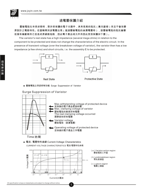
壓敏電阻在休息狀態時,對於受保護的電子元器件,具有很高的阻抗(數兆歐姆)而且不會改變
原設計之電路特性。但當瞬間突波電壓出現(超過壓敏電阻的崩潰電壓時),該壓敏電阻的阻抗會變
低僅有幾歐姆而已並造成原線路短路,因此電子產品或元件而因此受到保護如下圖)。
The varistor's rest state has a high impedance (several mega ohms) in relation to the
component to be protected and does not change the characteristics of the electric circuit. In the
presence of transient voltage (over the breakdown voltage of varistor), the varistor then has a low
impedance (a few ohms) and short circuits, i.e. the assembly E to be protected.
壓敏電阻之突波抑制功能 Surge Suppression of Varistor
Surge Suppression of Varistor
Max.withstanding voltage of protected device
受保护的电子产品最高耐压
Max. clamping voltage of varistor
压敏电阻的最高抑制电压
The real clamping voltage occurred
实际嵌制抑制电压
Varistor voltage
压敏电阻(崩溃电压)
Operating voltage of protected device
受保护的电子产品工作电压
Time 时间
電流 - 電壓特性曲線 Current-Voltage Characteristics
CURRENT-VOLTAGE CHARACTERISTICS 电流-电压特性曲线
1000 (a)Varistor action region
压敏电阻工作区
12-13
P=10 Ω-CM
(b)prebreakdown region
I=kv P=1-10Ω-cm 预先崩溃区
100
(c)upturn region
电压上扬区
(b) (a) ©( c ) ©
10
-8 -6 -4 -2 0 2
10 10 10 10 10 10 10
Current(A)电流
All specification is base on datasheets and subject to change without notice.
1
Voltage(V)电压
過電壓保護
www.joyin.com.tw
j O Y I N
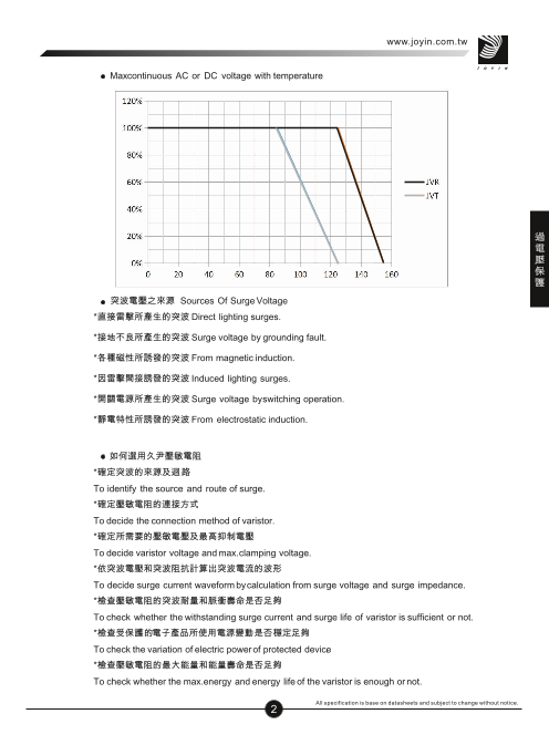
Maxcontinuous AC or DC voltage with temperature
突波電壓之來源 Sources Of Surge Voltage
*直接雷擊所產生的突波 Direct lighting surges.
*接地不良所產生的突波 Surge voltage by grounding fault.
*各種磁性所誘發的突波 From magnetic induction.
*因雷擊間接誘發的突波 Induced lighting surges.
*開關電源所產生的突波 Surge voltage byswitching operation.
*靜電特性所誘發的突波 From electrostatic induction.
如何選用久尹壓敏電阻
*確定突波的來源及迴路
To identify the source and route of surge.
*確定壓敏電阻的連接方式
To decide the connection method of varistor.
*確定所需要的壓敏電壓及最高抑制電壓
To decide varistor voltage and max.clamping voltage.
*依突波電壓和突波阻抗計算出突波電流的波形
To decide surge current waveform bycalculation from surge voltage and surge impedance.
*檢查壓敏電阻的突波耐量和脈衝壽命是否足夠
To check whether the withstanding surge current and surge life of varistor is sufficient or not.
*檢查受保護的電子產品所使用電源變動是否穩定足夠
To check the variation of electric powerof protected devic.e
*檢查壓敏電阻的最大能量和能量壽命是否足夠
To check whether the max.energy and energy life of the varistor is enough or not.
All specification is base on datasheets and subject to change without notice.
2
過電壓保護
www.joyin.com.tw
j O Y I N
*檢查下列關係是否正確:
Tocheckthe relation:
受保護的電子產品的最高耐電壓>壓敏電阻的最高抑制電壓 >真正產生之抑制電壓>壓敏電阻的崩潰電壓
>受保護電子產品的工作電壓
Max. withstanding voltageof protecteddevice>Max.clamping voltage of varistor>The real clamping voltage
occurred>Breakdown voltage of varistor>Operating voltage of protected device.
*若出現問題先檢查是否原因為漏電流太大
To check whether the problem caused by loss current of leakage.
*檢查壓敏電阻連接方式是否適當
*To check the connection method of varistor.
*檢查壓敏電阻負荷是否過大
To check the condition of varistor overload.
*檢查壓敏電阻於工作狀態下是否有其他任何問題
To check any other problems byvarious operation conditions.
*以受保護電子產品實際操作測試及確認使用的壓敏電阻是否適當
To test and to verify by real practice.
*檢查接地線的連接方式是否適當
*To check the connection of the grounding wire.
-Fuse current selection
如果保險絲與壓敏電阻串聯,以防止壓敏電阻損壞後的後續浪湧電流,保險絲電流可參考以下選擇:
Fuse current selection if fuse beingin series with varistor to protect from follow-on surge current after varistor
damaged.
Varistor 5mm 7mm 10mm 14mm 20mm
Nominal fuse current ≦ 1A ≦ 3A ≦ 5A ≦ 10A ≦ 10A
-壓敏電阻串聯或並聯使用確認項目
Check list in series and parallel operation of varistor
项目 串联 並联
较高电压。 较大电流。
目的 较高能量。 较高能量。
(不需挑选) (需要挑选)
应用范围 适用所有压敏电阻的电压及电流规格。 适用所有压敏电压,但较大电流的规格。
适用型号 需有相同的额定突波耐量。 适用所有压敏电阻的电压及电流规格。
必需是单一额定电压。
注意事项 耐浪湧电流额定值需相同。
必须挑选近似的V-I特性。
单一元件额定电流需相同。 额电电流决定于电流分配的方式。
提高额定电压。 需与单一元件的额定电压相同。
影响效果
提升额定能量。 额定能量与电流分配成正比。
提高残压电压。 残压决定于合成的V-I曲线
All specification is base on datasheets and subject to change without notice.
3
過電壓保護
www.joyin.com.tw
j O Y I N
Item Series Parallel
Objective Higher voltage capability Higher current capability
Higher energy capability Higher energy capability
(No Selection is required) (Selection is required)
Application Range All voltages and currents All voltages with higher current i.e.,>100A
Models Applicable Have same withstanding surge All models
current ratings
Precautions Withstanding surge current ratings Must be identical voltage rated models
must be equal Must test and select units for similarV-Icharacteristics
Effect on Rating The same current ratings with Current ratings function of current sharing
single unit The same voltage ratings with single unit
Increase rated voltage Energy ratings as above in proportion tocurrent sharing
Level up rated energy Clamp voltage determined by compositeV-I
Heighten clamp voltage characteristics of matched units
Varistor voltage selection in line circuit
Line Circuit
Power Supply voltage MOV Type
AC/ DC single-phase circuit
JV◇□□△201K JV◇□□△221K
100VAC
JV◇□□△241K JV◇□□△271K
JV◇□□△391K JV◇□□△431K
200VAC Protected
JV◇□□△471K device
12VDC JV◇□□△220K
24VDC JV◇□□△390K AC three-phase circuit
◇ : R& H=RoHS+Halogen free+Non flammable Protected
T=High temperature operating device
C=Copper electrode
□ : Elementsize (disc dia)
△ : Surge current Capability(N or S or Useries)
Line and Ground
AC / DC single -phase circuit
Varistor voltage selection in line to ground circuit
Protected
device
PowerSupply voltage MOV Type
JV◇□□△431K JV◇□□△471K
100VAC, 200VAC
JV◇ □□△751K JV◇ □□△182K
◇ : R& H=RoHS+Halogen free+Non flammable
T=High temperature operating AC three-phase circuit
C=Copper electrode
□ : Element size (disc dia)
△ : Surge current Capability(N or S or Useries) Protected
device
All specification is base on datasheets and subject to change without notice.
4
過電壓保護
www.joyin.com.tw
j O Y I N
Switching Circuit Protection
Varistor voltage selection in switching circuit protection Relay protection Spark elimination Semiconductor protection
Power Supplyvoltage MOV Type
12V DC JV◇□□△220K
24V DC JV◇□□ △390K
100V DC JV◇□□△151K
JV◇□□△201K JV◇□□△241K
100V AC
JV◇□□△22 1K JV◇□□△271K
◇ : R& H=RoHS+Halogen free+Non flam mable
T=High temperature operating
C=Copper electrode
□ : Element size (disc dia)
△ : Surge current Capability(N or S or Useries)
S ur ge p ro tec ti on o f si ng al li ne Firealarm system
Thyristor p rotection TRIAC protection
Solenoid Contact Protection
Solenoid Solenoid
Stove & Boiler Brake & Clutch
Brake
clutch
Electronic circuit
Varistor voltage sele ction in t e lecommunication circ uit protection Telecommunication circuit protection
Power Supply
volt
age M
OV Type
JV◇□□△220L
12V DC
JV◇□□△820KtoJV◇□□△182K
JV◇ □□△390
K
24V DC
JV◇□□△820KtoJV◇□□△182K
◇ : R& H =RoHS+ Halo gen fre e+Non flammable
T =High temperatur e o pe r ating
C=Copper electrode
□ : Element size (disc dia)
△ : Surge current Capability(N or S or Useries)
All specification is base on datasheets and subject to change without notice.
5
過電壓保護
www.joyin.com.tw
j O Y I N
ORDERING CODE
JV R 07 N 181 K 6 5 Y AW
Joyin ZnO Varistor
久尹氧化鋅壓敏電阻
LEAD length& Packaging
腳長及包裝方式
R/H=EPOXY Coating& 5
0=5±1.0mmfor Straight lead
OperatingTemperature 85℃ 5±0.5mmfor Kink lead
U4=24mm min. for Bulk and Kink lead
U5=25mmmin.for Bulk and Straight lead
AW =H0 16mmfor Ammo and Kink lead
AY =H0 20mmfor Ammo and Straight lead
Element Size (Disc Dia.) RW =H0 16mmfor T/R and Kink lead
瓷片直徑別 RY =H0 20mmfor T/R and Straight lead
05=Φ 5mm *Special specper request.
07=Φ 7mm
10=Φ 10mm
14=Φ 14mm
20=Φ 20mm
25=Φ 25mm Lead Style 腳型
Y=Vertical Kink Lead (standard)
P=Straight Lead
*Special lead styles per request
Standard標準系列
Lead Spacing 線距
Varistor Voltage電壓值 5=5.0mm
The first two digits indicate voltage.
7=7.5mm
1=10mm
前兩位數字代表電壓
The third digit signifies th e number of zeroe
s .
第三位數字代表電壓10的次方
For example 例如:
080 =8V Lead Diameter線徑
180 =18V 6=0.6± 0.05mm
181 =180V 8=0.8± 0.05mm
1=1.0± 0.05mm
182 =1800V
Varistor Voltage Tolerance壓敏電壓容許 差
K =±10%
L =±15%
M=±20%
P =±25%
All specification is base on datasheets and subject to change without notice.
6
過電壓保護
www.joyin.com.tw
j O Y I N
RATING AND CHARATERISTICS
Standard Varistors - 5mm
Withstanding Nominal
Varistor Maximum Maximum
Surge Discharge Rated Energy
Voltage Allowable Clamping Certification
Current Current Wattage (10/1000us)
Part No. at 0.1mA Voltage Voltage
(8/20us) (8/20us)
DC AC rms DC V@ ic ic 1 Time In
Tolerance (W) (J)
( V ) ( V ) ( V ) ( V ) ( A ) ( A ) ( KA )
JVR 05N 180M 18 ±20% 11 14 40 1 100 0.1 0.01 0.6
☆ ✯ ✬
JVR 05N 220L 22 ±15% 14 18 48 1 100 0.1 0.01 0.7 ☆ ✯ ✬
JVR 05N 270K 27 ±10% 17 22 60 1
100
0.1 0.01 0.9 ☆ ✯ ✬
JVR 05N 330K 33 ±10% 20 26 73 1 100 0.1 0.01 1.1 ☆ ✯ ✬
JV R 0 5 N 3 9 0 K 39 ± 1 0 % 2 5 31 8 6 1 1 0 0 0 . 1 0.01 1.2 ☆ ✯ ✬
J VR 05N 470K 47 ±10% 30 38 104 1 1 00 0.1 0.01 1.5 ☆ ✯ ✬
JVR 05N 560K 56 ±10% 35 45 123 1 100 0.1 0.01 1.8 ☆ ✯ ✬
JVR 05N 680K 68 ±10% 40 56 150 1 100 0.1 0.01 2.1 ☆ ✯ ✬
JVR 05N 820K 82 ±10% 50 65 145 5 400 0.1 0.1 2.8 ☆ ✯ ✬
JVR 05N 101K 100 ±10% 60 85 175 5 400 0.1 0.1 3.5 ☆ ✯ ✬
JVR 05N 121K 120 ±10% 75 100 210 5 400 0.1 0.1 4 ☆ ✯ ✬
JVR 05N 151K 150 ±10% 95 125 260 5 400 0.1 0.1 5.5 ☆ ✯ ✬
JVR 05N 181K 180 ±10% 115 150 320 5 400 0.1 0.1 6.5 ☆ ✯ ✬
JVR 05N 201K 200 ±10% 130 170 355 5 400 0.1 0.1 7.1 ☆ ✯ ✬
JVR 05N 221K 220 ±10% 140 180 380 5 400 0.1 0.1 7.8 ☆ ✯ ✬
JVR 05N 241K 240 ±10% 150 200 415 5 400 0.1 0.1 8.4 ☆ ✯ ✬
JVR 05N 271K 270 ±10% 175 225 475 5 400 0.1 0.1 9.9 ☆ ✯ ✬
JVR 05N 301K 300 ±10% 195 250 525 5 400 0.1 0.1 10.5 ☆ ✯ ✬
JVR 05N 331K 330 ±10% 210 275 575 5 400 0.1 0.1 11.5 ☆ ✯ ✬
JVR 05N 361K 360 ±10% 230 300 620 5 400 0.1 0.1 13 ☆ ✯ ✬
JVR 05N 391K 390 ±10% 250 320 675 5 400 0.1 0.1 15 ☆ ✯ ✬
JVR 05N 431K 430 ±10% 275 350 745 5 400 0.1 0.1 16.5 ☆ ✯ ✬
JVR 05N 471K 470 ±10% 300 385 810 5 400 0.1 0.1 17.5 ☆ ✯ ✬
JVR 05N 511K 510 ±10% 320 418 880 5 400 0.1 0.1 18.5 ☆ ✯ ✬
JVR 05N 561K 560 ±10% 350 460 940 5 400 0.1 0.1 19.5 ☆ ✯ ✬
JVR 05N 621K 620 ±10% 385 505 1050 5 400 0.1 0.1 20.5 ☆ ✯ ✬
JVR 05N 681K 680 ±10% 420 560 1150 5 400 0.1 0.1 21.5 ☆ ✯ ✬
JVR 05N 751K 750 ±10% 460 615 1290 5 400 0.1 0.1 22.5 ☆ ✯ ✬
Application notes for UL,CS A,VD E an d CQ C r eco nized related sta ndards
UL CUL VDE CQC
IEC61051-1
GB4943.1-2011
UL 1449 IEC61051-1 IEC61051-2
Standard N0. CSA 22.2
GB/T1093-1997 GB/T1093-1997
TH IEC61051-2 IEC61051-2-24 Edition No . 269.5 GB/T10194-1997 GB/T10194-1997IEC61051-2-2 IE C6095 0-1:2013AnnexQ
GB8898 -2011
IEC62368-1:2014 / G.8.2
Transient Voltage Transient Voltage
Title Varistors for use in electronic equipment Engaged inVoluntary Product Certification
Surge Suppressors Surge Suppressors
Certificate No. VZCA2.E325508 VZCA8.E325508 5937 CQC07001019159/9161/9162/9163/9164
Symbols ☆ ✯ ★ ✬ ✪
All specification is base on datasheets and subject to change without notice.
7
過電壓保護
www.joyin.com.tw
j O Y I N
Pulse Life time Ratings-5mm V-I Characteristic Curve-5mm
05N 180M~05N 680K 05N 180M~05N 680K
300
200
100
80
60
1
40 Pulse
20
2
1
10 0
8 10 2
6
1
4 0
3
10 4
10 5
2
10 6
1
0.8
0.6
0.4
0.2
0.1
20 100 1,000 10,000
Rectangular wave (μsec.)
05N 820K~05N 751K 05N 820K~05N 751K
400
300
200
1Pu
100 lse
80
60 2
40
10
30
20 10 2
10 3
10
10 48
10 5
6
10 6
4
2
1
0.8
0.6
0.4
0.2
20 100 1,000 10,000
Rectangular wave (μsec.)
All specification is base on datasheets and subject to change without notice.
8
Imax. (A)
Imax. (A)
過電壓保護
www.joyin.com.tw
j O Y I N
RATING AND CHARATERISTICS
Standard Varistors - 7mm
Withstanding Nominal
Va r istor Maximum Maximum
Surge Discharge Rated Energy
Voltage Allowable Clamping Certification
Current Current Wattage (10/1000us)
Part No. at 1mA Voltage Voltage
(8/20us) (8/20us)
DC AC rms DC V@ ic ic 1 Time In
Toleran ce ( W ) (J)
( V ) ( V ) ( V ) ( V ) ( A ) ( A ) ( KA )
JVR 07N 180M 18 ±20% 11 14 40 2.5 250 0.2 0.02 1.2 ☆ ✯ ✬
JVR 07N 220L 22 ±15% 14 18 48 2.5 250 0.2 0.02 1.4 ☆ ✯ ✬
JVR 07N 270K 27 ±10% 17 22 60 2.5 250 0.2 0.02 1.7 ☆ ✯ ✬
JVR 07N 330K 33 ±10% 20 26 73 2.5 250 0.2 0.02 2.2 ☆ ✯ ✬
JVR 07N 390K 39 ±10% 25 31 86 2.5 250 0.2 0.02 2.4 ☆ ✯ ✬
JVR 07N 470K 47 ±10% 30 38 104 2.5 250 0.2 0.02 3.0 ☆ ✯ ✬
JVR 07N 560K 56 ±10% 35 45 123 2.5 250 0.2 0.02 3.5 ☆ ✯ ✬
JVR 07N 680K 68 ±10% 40 56 150 2.5 250 0.2 0.02 4.3 ☆ ✯ ✬
JVR 07N 820K 82 ±10% 50 65 145 10 1200 0.5 0.25 5.5 ☆ ✯ ✬
JVR 07N 101K 100 ±10% 60 85 175 10 1200 0.5 0.25 7.0 ☆ ✯ ✬
JVR 07N 121K 120 ±10% 75 100 210 10 1200 0.5 0.25 8.0 ☆ ✯ ✬
JVR 07N 151K 150 ±10% 95 125 260 10 1200 0.5 0.25 11.0 ☆ ✯ ✬
JVR 07N 181K 180 ±10% 115 150 320 10 1200 0.5 0.25 13.0 ☆ ✯ ✬
JVR 07N 201K 200 ±10% 130 170 355 10 1200 0.5 0.25 14.3 ☆ ✯ ✬
JVR 07N 221K 220 ±10% 140 180 380 10 1200 0.5 0.25 15.5 ☆ ✯ ✬
JVR 07N 241K 240 ±10% 150 200 415 10 1200 0.5 0.25 16.8 ☆ ✯ ✬
JVR 07N 271K 270 ±10% 175 225 475 10 1200 0.5 0.25 19.8 ☆ ✯ ✬
JVR 07N 301K 300 ±10% 195 250 525 10 1200 0.5 0.25 21.0 ☆ ✯ ✬
JVR 07N 331K 330 ±10% 210 275 575 10 1200 0.5 0.25 23.0 ☆ ✯ ✬
JVR 07N 361K 360 ±10% 230 300 620 10 1200 0.5 0.25 26.0 ☆ ✯ ✬
JVR 07N 391K 390 ±10% 250 320 675 10 1200 0.5 0.25 30.0 ☆ ✯ ✬
JVR 07N 431K 430 ±10% 275 350 745 10 1200 0.5 0.25 33.0 ☆ ✯ ✬
JVR 07N 471K 470 ±10% 300 385 810 10 1200 0.5 0.25 35.0 ☆ ✯ ✬
JVR 07N 511K 510 ±10% 320 418 880 10 1200 0.5 0.25 37.0 ☆ ✯ ✬
JVR 07N 561K 560 ±10% 350 460 940 10 1200 0.5 0.25 39.0 ☆ ✯ ✬
JVR 07N 621K 620 ±10% 385 505 1050 10 1200 0.5 0.25 41.0 ☆ ✯ ✬
JVR 07N 681K 680 ±10% 420 560 1150 10 1200 0.5 0.25 43.0 ☆ ✯
✬
JVR 07N 751K 750 ±10% 460 615 1290 10 1200 0.5 0.25 45.0 ☆ ✯ ✬
JVR 07N 781k 780 ±10% 485 640 1290 10 1200 0.5 0.25 46.0 ☆ ✯ ✬
JVR 07N 821k 820 ±10% 510 670 1355 10 1200 0.5 0.25 47.0 ☆ ✯ ✬
All specification is base on datasheets and subject to change without notice.
9
過電壓保護
www.joyin.com.tw
j O Y I N
Pulse Life time Ratings-7mm V-I Characteristic Curve-7mm
07N 820K~07N 821K 07N 820K~07N 821K
2,000
1,000
800
600
400
1Pulse
200
2
100 10
80
60 10 2
40
10 3
20 10 4
10 5
10 6
10
8
6
4
2
1
0.8
20 100 1,000 10,000
07N 180M~07N 680K 07N 180M~07N 680K
All specification is base on datasheets and subject to change without notice.
10
Imax. (A)
過電壓保護
www.joyin.com.tw
j O Y I N
RATING A ND C HARATERISTICS
Standard V aristors- 1 0 mm
Withstanding Nominal
Varistor Maximum Maximum
S urge Discharge Rated Energy
Voltage Allowable Clamping Certification
Cu rrent Current Wattage (10/1000us)
Part No. at 1mA Voltage Voltage
(8/20us) (8/20us)
DC AC rms DC V@ ic ic 1 Time In
Toleran
( V )
c e ( V ) ( V )
(W) (J)
( V ) ( A ) ( A ) ( KA )
JVR 10N 180M 18 ±20% 11 14 36 5 5 00 0.3 0.05 2.4 ☆ ✯ ✬
JVR 10N 220L 22 ±15% 14 18 43 5 500 0.3 0.05 2.7 ☆ ✯ ✬
JVR 10N 270K 27 ±10% 17 22 53 5 500 0.3 0.05 3.5 ☆ ✯ ✬
JVR 10N 330K 33 ±10% 20 26 65 5 500 0.3 0.05 4.4 ☆ ✯ ✬
JVR 10N 390K 39 ±10% 25 31 77 5 500 0.3 0.05 4.7 ☆ ✯ ✬
JVR 10N 470K 47 ±10% 30 38 93 5 500 0.3 0.05 6.0 ☆ ✯ ✬
JVR 10N 560K 56 ±10% 35 45 110 5 500 0.3 0.05 7.0 ☆ ✯ ✬
JVR 10N 680K 68 ±10% 40 56 135 5 500 0.3 0.05 8.5 ☆ ✯ ✬
JVR 10N 820K 82 ±10% 50 65 135 25 2500 1.5 0.4 11.0 ☆ ✯ ✬
JVR 10N 101K 100 ±10% 60 85 165 25 2500 1.5 0.4 14.0 ☆ ✯ ✬
JVR 10N 121K 120 ±10% 75 100 200 25 2500 1.5 0.4 16.0 ☆ ✯ ✬
JVR 10N 151K 150 ±10% 95 125 250 25 2500 1.5 0.4 22.0 ☆ ✯ ✬
JVR 10N 181K 180 ±10% 115 150 300 25 2500 1.5 0.4 26.0 ☆ ★ ✬
JVR 10N 201K 200 ±10% 130 170 340 25 2500 1.5 0.4 28.5 ☆ ★ ✪
JVR 10N 221K 220 ±10% 140 180 360 25 2500 1.5 0.4 31.0 ☆ ★ ✪
JVR 10N 241K 240 ±10% 150 200 395 25 2500 1.5 0.4 33.5 ☆ ★ ✪
JVR 10N 271K 270 ±10% 175 225 455 25 2500 1.5 0.4 39.5 ☆ ★ ✪
JVR 10N 301K 300 ±10% 195 250 505 25 2500 1.5 0.4 42.0 ☆ ★ ✪
JVR 10N 331K 330 ±10% 210 275 550 25 2500 1.5 0.4 46.0 ☆ ★ ✪
JVR 10N 361K 360 ±10% 230 300 595 25 2500 1.5 0.4 52.0 ☆ ★ ✪
JVR 10N 391K 390 ±10% 250 320 650 25 2500 1.5 0.4 60.0 ☆ ★ ✪
JVR 10N 431K 430 ±10% 275 350 710 25 2500 1.5 0.4 66.0 ☆ ★ ✪
JVR 10N 471K 470 ±10% 300 385 775 25 2500 1.5 0.4 70.0 ☆ ★ ✪
JVR 10N 511K 510 ±10% 320 418 842 25 2500 1.5 0.4 74.0 ☆ ★ ✪
JVR 10N 561K 560 ±10% 350 460 920 25 2500 1.5 0.4 78.0 ☆ ★ ✪
JVR 10N 621K 620 ±10% 385 505 1025 25 2500 1.5 0.4 82.0 ☆ ★ ✪
JVR 10N 681K 680 ±10% 420 560 1120 25 2500 1.5 0.4 86.0 ☆ ★ ✪
JVR 10N 751K 750 ±10% 460 615 1240 25 2500 1.5 0.4 90.0 ☆ ★ ✪
JVR 10N 781K 780 ±10% 485 640 1290 25 2500 1.5 0.4 92.0 ☆ ★ ✪
JVR 10N 821K 820 ±10% 510 670 1355 25 2500 1.5 0.4 94.0 ☆ ★ ✪
JVR 10N 911K 910 ±10% 550 745 1500 25 2500 1.5 0.4 102.0 ☆ ★ ✪
JVR 10N 102K 1000 ±10% 625 825 1650 25 2500 1.5 0.4 112.0 ☆ ★ ✪
JVR 10N 112K 1100 ±10% 680 895 1815 25 2500 1.5 0.4 124.0 ☆ ★ ✪
JVR 10N 122K 1200 ±10% 720 975 1980 25 2500 1.5 0.4 134.0 ☆ ✯ ✪
JVR 10N 142K 1400 ±10% 825 1135 2310 25 2500 1.5 0.4 148.0 ☆ ✯ ✪
JVR 10N 162K 1600 ±10% 920 1300 2640 25 2500 1.5 0.4 162.0 ☆ ✯ ✪
JVR 10N 182K 1800 ±10% 1000 1465 2970 25 2500 1.5 0.4 174.0 ☆ ✯ ✪
All specification is base on datasheets and subject to change without notice.
11
過電壓保護
www.joyin.com.tw
j O Y I N
Pulse Life time Ratings-10mm V-I Characteristic Curve-10mm
500
300
200
1Pulse
100
80 2
60
10
40
10 2
30
10 3
20 10 4
10 5
10 10 6
8
6
4
2
1
0.8
0.6
0.4
0.2
20 100 1,000 10,000
Rectangular wave (μsec.)
10N 820K~10N 471K
3,000
2,000
1,000
800
600
400
2
200 10
100 2
80
60 10 3
1
40 0 4
10 5
20
10 6
10
8
6
4
2
1
20 100 1,000 10,000
Rectangular wave (μsec.)
10N 511K~10N 182K
3,000
2,000
1,000
800
600
400
2
200 10
100 2
80
60 10 3
1
40 0 4
10 5
20
10 6
10
8
6
4
2
1
20 100 1,000 10,000
Rectangular wave (μsec.)
All specification is base on datasheets and subject to change without notice.
12
Imax.(A) Imax.(A) Imax.(A)
過電壓保護
ls
e se
Pu u
l
1 10 1P 10
www.joyin.com.tw
j O Y I N
RATING A ND CHAR ATERISTICS
Standard Varistors - 14mm
W ithstanding Nominal
Varistor Maximum Maximum
Surge Discharge Rated Energy
Voltage Allowable Clamping Certification
Current Cu
r r e n t Wat tage (10/1000us)
Part No. at 1mA Voltage Voltage
(8/20us) (8/20us)
DC AC rm s D C V @ i c i c 1 T i m e I n
( V )
Tolerance
( V ) ( V ) ( V ) ( A ) ( A ) ( KA )
( W ) ( J )
JVR 14N 180M 18 ±20% 11 14 36 10 1000 1 0.1 4.7 ☆ ✯ ✬
JVR 14N 220L 22 ±15% 14 18 43 10 1000 1 0.1 5.4 ☆ ✯ ✬
JVR 14N 270K 27 ±10% 17 22 53 10 1000 1 0.1 6.9 ☆
✯ ✬
JVR 14N 330K 33 ±10% 20 26 65 10 1000 1 0.1 8.8 ☆ ✯ ✬
JVR 14N 390K 39 ±10% 25 31 77 10 1000 1 0.1 9.4 ☆ ✯ ✬
JVR 14N 470K 47 ±10% 30 38 93 10 1000 1 0.1 12.0 ☆ ✯ ✬
JVR 14N 560K 56 ±10% 35 45 110 10 1000 1 0.1 14.0 ☆ ✯ ✬
JVR 14N 680K 68 ±10% 40 56 135 10 1000 1 0.1 17.0 ☆ ✯ ✬
JVR 14N 820K 82 ±10% 50 65 135 50 4500 3.0 0.6 22.0 ☆ ✯ ✬
JVR 14N 101K 100 ±10% 60 85 165 50 4500 3.0 0.6 28.0 ☆ ✯ ✬
JVR 14N 121K 120 ±10% 75 100 200 50 4500 3.0 0.6 32.0 ☆ ✯ ✬
JVR 14N 151K 150 ±10% 95 125 250 50 4500 3.0 0.6 44.0 ☆ ✯ ✬
JVR 14N 181K 180 ±10% 115 150 300 50 4500 3.0 0.6 52.0
☆ ★ ✬
JVR 14N 201K 200 ±10% 130 170 340 50 4500 3.0 0.6 57.0 ☆ ★ ✪
JVR 14N 221K 220 ±10% 140 180 360 50 4500 3.0 0.6 62.0 ☆ ★ ✪
JVR 14N 241K 240 ±10% 150 200 395 50 4500 3.0 0.6 67.0 ☆ ★ ✪
JVR 14N 271K 270 ±10% 175 225 455 50 4500 3.0 0.6 79 ☆ ★ ✪
JVR 14N 301K 300 ±10% 195 250 505 50 4500 3.0 0.6 84.0 ☆ ★ ✪
JVR 14N 331K 330 ±10% 210 275 550 50 4500 3.0 0.6 92.0 ☆ ★ ✪
JVR 14N 361K 360 ±10% 230 300 595 50 4500 3.0 0.6 104.0 ☆ ★ ✪
JVR 14N 391K 390 ±10% 250 320 650 50 4500 3.0 0.6 120.0 ☆ ★ ✪
JVR 14N 431K 430 ±10% 275 350 710 50 4500 3.0 0.6 132.0 ☆ ★ ✪
JVR 14N 471K 470 ±10% 300 385 775 50 4500 3.0
0.6 140.0 ☆ ★ ✪
JVR 14N 511K 510 ±10% 320 418 842 50 4500 3.0 0.6 148.0 ☆ ★ ✪
JVR 14N 561K 560 ±10% 350 460 920 50 4500 3.0 0.6 156.0 ☆ ★ ✪
JVR 14N 621K 620 ±10% 385 505 1025 50 4500 3.0 0.6 164.0 ☆ ★ ✪
JVR 14N 681K 680 ±10% 420 560 1120 50 4500 3.0 0.6 172.0 ☆ ★ ✪
JVR 14N 751K 750 ±10% 460 615 1240 50 4500 3.0
0.6 180.0 ☆ ★ ✪
JVR 14N 781K 780 ±10% 485 640 1290 50 4500 3.0 0.6 184.0 ☆ ★ ✪
JVR 14N 821K 820 ±10% 510 670 1355 50 4500 3.0 0.6 188.0 ☆ ★ ✪
JVR 14N 911K 910 ±10% 550 745 1500 50 4500 3.0 0.6 204.0 ☆ ★ ✪
JVR 14N 102K 1000 ±10% 625 825 1650 50 4500 3.0 0.6 224.0 ☆ ★ ✪
JVR 14N 112K 1100 ±10% 680 895 1815 50 4500 3.0 0.6 248.0 ☆ ★ ✪
JVR 14N 122K 1200 ±10% 720 975 1980 50 4500 2.0 0.6 268.0
☆
★ ✪
JVR 14N 142K 1400 ±10% 825 1135 2310 50 4500 2.0 0.6 300.0 ☆ ★ ✪
JVR 14N 162K 1600 ±10% 920 1300 2640 50 4500 2.0 0.6 328.0 ☆ ★ ✪
JVR 14N 182K 1800 ±10% 1000 1465 2970 50 4500 2.0 0.6 348.0 ☆ ★ ✪
All specification is base on datasheets and subject to change without notice.
13
過電壓保護
www.joyin.com.tw
j O Y I N
Pulse Life time Ratings-14mm V-I Characteristic Curve-14mm
14N 180M~14N 680K 14N 180M~14N 680K
2,000
1,000
800
600
400
1Pul
200 se
2
100
80 10
60 10 2
3
40
10
10 4
20
10 5
10 6
10
8
6
4
2
1
0.8
20 100 1,000 10,000
Rectangular Wave(μ sec.)
5,000
4,000
3,000
2,000
1,000
800
600
400
200 10 2
10 3
100
80
1
60 0
4
10 5
40
10
6
20
10
8
6
4
3
20 100 1000 10000
Rectangular Wave(μ sec.)
5,000
4,000
3,000
2,000
1,000
800
600
400
200 10 2
10 3
100
80
10 460
10 5
40
10
6
20
10
8
6
4
3
20 100 1000 10000
Rectangular Wave(μ sec.)
All specification is base on datasheets and subject to change without notice.
14
Imax.(A)
Imax.(A) Imax. (A)
過電壓保護
e
se l
s
ul 2 0 1P
u 2 10
1P
1
www.joyin.com.tw
j O Y I N
RATIN G AND CH A RATERISTICS
Standard Varistors - 20mm
Withstanding Nominal
Var istor Ma ximum M aximum
S u r ge Discharge Rated Energy
Voltage Allowable Clamping Certification
Current Current Wattage (10/1000us)
Part No. at 1mA Voltage Voltage
(8/20us) (8/20us)
DC AC rms DC V@ ic ic 1 Tim e In
Tolerance (W) (J)
( V ) ( V ) ( V ) ( V ) ( A ) ( A ) ( KA )
JVR 20N 220M 22 ±20% 14 18 43 20 2000 2 0.2 8.0 ☆ ✯ ✬
JVR 20N 270M 27 ±20% 17 22 53 20 2000 2 0.2 10.0 ☆ ✯ ✬
JVR 20N 330M 33 ±20% 20 26 65 20 2000 2 0.2 12.0 ☆ ✯ ✬
JVR 20N 390L 39 ±15% 25 31 77 20 2000 2 0.2 14.0 ☆ ✯ ✬
JVR 20N 470L 47 ±15% 30 38 93 20 2000 2 0.2 17.0 ☆ ✯ ✬
JVR 20N 560L 56 ±15% 35 45 110 20 2000 2 0.2 20.0 ☆ ✯ ✬
JVR 20N 680L 68 ±15% 40 56 135 20 2000 2 0.2 24.0
☆ ✯ ✬
JVR 20N 820L 82 ±15% 50 65 135 100 6500 4 1 44.0 ☆ ✯ ✬
JVR 20N 101K 100 ±10% 60 85 165 100 6500 4.0 1 56.0 ☆ ✯ ✬
JVR 20N 121K 120 ±10% 75 100 200 100 6500 4.0 1 64.0 ☆ ✯ ✬
JVR 20N 151K 150 ±10% 95 125 250 100 6500 4.0 1 88.0 ☆ ✯ ✬
JVR 20N 181K 180 ±10% 115 150 300 100 6500 4.0 1 104.0 ☆ ★ ✬
JVR 20N 201K 200 ±10% 130 170 340 100 6500 4.0 1 114.0 ☆ ★ ✪
JVR 20N 221K 220 ±10% 140 180 360 100 6500 4.0 1 124.0 ☆ ★ ✪
JVR 20N 241K 240 ±10% 150 200 395 100 6500 4.0 1 134.0 ☆ ★ ✪
JVR 20N 271K 270 ±10% 175 225 455 100 6500 4.0 1 158.0 ☆ ★ ✪
JVR 20N 301K 300 ±10% 195 250 505 100 6500 4.0 1 168 ☆ ★ ✪
JVR 20N 331K 330 ±10% 210 275 550 100 6500 4.0 1 184.0
☆ ★ ✪
JVR 20N 361K 360 ±10% 230 300 595 100 6500 4.0 1 208.0 ☆ ★ ✪
JVR 20N 391K 390 ±10% 250 320 650 100 6500 4.0 1 240.0 ☆ ★ ✪
JVR 20N 431K 430 ±10% 275 350 710 100 6500 4.0 1 264.0 ☆ ★ ✪
JVR 20N 471K 470 ±10% 300 385 775 100 6500 4.0 1 280.0 ☆ ★ ✪
JVR 20N 511K 510 ±10% 320 418 842 100 6500 4.0 1 296.0 ☆ ★ ✪
JVR 20N 561K 560 ±10% 350 460 920 100 6500 4.0 1 312.0 ☆ ★ ✪
JVR 20N 621K 620 ±10% 385 505 1025 100 6500 4.0 1 328.0 ☆ ★ ✪
JVR 20N 681K 680 ±10% 420 560 1120 100 6500 4.0 1 344.0 ☆ ★ ✪
JVR 20N 751K 750 ±10% 460 615 1240 100 6500 4.0 1 360.0
☆ ★ ✪
JVR 20N 781K 780 ±10% 485 640 1290 100 6500 4.0 1 368.0 ☆ ★ ✪
JVR 20N 821K 820 ±10% 510 670 1355 100 6500 4.0 1 376.0 ☆ ★ ✪
JVR 20N 911K 910 ±10% 550 745 1500 100 6500 4.0 1 408.0 ☆ ★ ✪
JVR 20N 102K 1000 ±10% 625 825 1650 100 6500 4.0 1 448.0 ☆ ★ ✪
JVR 20N 112K 1100 ±10%
680
895 1815 100 6500
4.0 1
496.0 ☆ ★ ✪
JVR 20N 122K 1200 ±10% 720 975 1980 100 6500 3.0 1 528.0 ☆ ★ ✪
JVR 20N 142K 1400 ±10% 825 1135 2310 100 6500 3.0 1 596.0 ☆ ★ ✪
JVR 20N 162K 1600 ±10% 920 1300 2640 100 6500 3.0 1 656.0 ☆ ★ ✪
JVR 20N 182K 1800 ±10% 1000 1465 2970 100 6500 3.0 1 695.0 ☆ ★ ✪
All specification is base on datasheets and subject to change without notice.
15
過電壓保護
www.joyin.com.tw
Pulse Life time Ratings-20mm V-I Characteristic Curve-20mm j O Y I N
20N 220M~20N 680L 20N 220M~20N 680L
3,000
2,000
1,000
800
600
400
2
200 10
2
100
1
80 0 3
60
10 4
40
10 5
20
10 6
10
8
6
4
2
1
20 100 1,000 10,000
Rectangular wave (μsec.)
7,000
5,000
4,000
3,000
2,000
1,000
800
600
10
400
10 2
200
10 3
100 10 4
80
60 10 5
40 1 6
20
10
8
6
4
2
20 100 1000 10000
Rectangular Wave(μ sec.)
7,000
5,000
4,000
3,000
2,000
1,000
800
600
10
400
10 2
200
10 3
100 10 4
80
60 10 5
40 10 6
20
10
8
6
4
2
20 100 1000 10000
Rectangular Wave(μ sec.)
All specification is base on datasheets and subject to change without notice.
16
Imax.(A) Imax.(A)
Imax.(A)
過電壓保護
ls
e e
Pu 10 l
s e
1 u 2 l
s
u 2
1P 1P
www.joyin.com.tw
j O Y I N
RATI
NG AND
CHARATERISTICS
Standard Varistors - 25mm
Varistor Maximum
Withstanding Nominal
Maximum
Surge Di scharge Rate d Ene rgy
Voltage Allowable Clamping Certification
Current C u r r e n t Wa ttage (10/1000us)
Pa rt No. at 1mA Voltage Voltage
(8/20us) (8/20us)
DC AC rmsTolerance
D C V @ ic i c 1 T im e I n ( W ) ( J )
( V ) ( V ) ( V ) ( V ) ( A ) ( A ) ( KA )
JVR 25N 201K 200 ±10% 130 170 355 150 20000 5 1.2 190.0 ☆ ★
JVR 25N 221K 220 ±10% 140 180 380 150 20000 5 1.2 205.0 ☆ ★
JVR 25N 241K 240 ±10% 150 200 415 150 20000 5 1.2 225.0 ☆ ★
JVR 25N 271K 270 ±10% 175 225 445 150 20000 5 1.2 255.0 ☆ ★
JVR 25N 301K 300 ±10% 195 250 495 150 20000 5 1.2 280.0 ☆ ★
JVR 25N 331K 330 ±10% 210 275 545 150 20000 5 1.2 305.0 ☆ ★
JVR 25N 361K 360 ±10% 230 300 595 150 20000 5 1.2 330.0 ☆ ★
JVR 25N 391K 390 ±10% 250 320 645 150 20000 5 1.2 360.0 ☆ ★
JVR 25N 431K 430 ±10% 275 350 710 150 20000 5.0 1.2 380.0 ☆ ★
JVR 25N 471K 470 ±10% 300 385 775 150 20000 5.0 1.2 400.0 ☆ ★
JVR 25N 511K 510 ±10% 320 418 840 150 20000 5.0 1.2 420.0
☆ ★
JVR 25N 561K 560 ±10% 350 460 925 150 20000 5.0 1.2 440.0 ☆ ★
JVR 25N 621K 620 ±10% 385 505 1025 150 20000 5.0 1.2 460.0 ☆ ★
JVR 25N 681K 680 ±10% 420 560 1125 150 20000 5.0 1.2 480.0 ☆ ★
JVR 25N 751K 750 ±10% 460 615 1240 150 20000 5.0 1.2 520.0 ☆ ★
JVR 25N 781K 780 ±10% 485 640 1290 150 20000 5.0 1.2 540.0 ☆ ★
JVR 25N 821K 820 ±10% 510 670 1360 150 20000 5.0 1.2 570 ☆ ★
JVR 25N 911K 910 ±10% 550 745 1500 150 20000 5.0 1.2 620.0 ☆ ★
All specification is base on datasheets and subject to change without notice.
17
過電壓保護
www.joyin.com.tw
j O Y I N
Pulse Life time Ratings-25mm V-I Characteristic Curve-25mm
20000
15000
10000
5000 1Pulse
2
10
1000 2
10 3
10 4
10 5
100 10 6
10
2
20 100 1000 10000
Rectangular Wave(μ sec.)
20000
15000
10000
5000 1Pulse
2
10
1000 2
10 3
10 4
10 5
100 10 6
10
2
20 100 1000 10000
Rectangular Wave(μ sec.)
All specification is base on datasheets and subject to change without notice.
18
Imax.(A) Imax.(A)
過電壓保護
10 10
www.joyin.com.tw
j O Y I N
JOYIN CO., LTD
Metal Oxide Varistor
■Reliability-JVR
Test description Standard Test condition Test requirement
After gradually applying the load specified below and
keeping the unit fixed for 10±1 seconds.
Tensile Strength
IEC60068-2-21 Terminal diameter Force
No visible damage
of Terminals (mm) (Kg) △Vb%≦±5%
0.5<d≤0.8 1.0
0.8<d≤1.25 2.0
Hold specim en a nd apply the for ce specifie d below to e ach
lead. Ben d the spe cime n to 90°,then ret urn t o the origin al
position. Repeat the procedure in the opposite direction.
Bending No visible damage
Strength of IEC60068-2-21
Terminal diameter Force △Vb%≦±5%
Terminals (mm) (Kg)
0.5<d≤0.8 0.5
0.8<d≤1.25 1.0
Frequency range : 10Hz~55Hz
N o v i s i b le d a m a ge
Vibration IEC60068-2-6 Amplitude : 0.75㎜ or 98 m/s2
△Vb%≦±5%
Direction : 3 mutually per pen dicula r d i r e c ti o n s , 2 h r s e a c h .
At least 95% of terminal
Bath temperature : 245±3℃
Solderability IEC60068-2-20 electrode is cov
Immersion time : 3±0.3 sec
ered b
y
n e w s o ld e r
Resistance to Bath tempe rature : 260±3℃ N o v is ib l e d a m a g e
IEC60068-2-20
soldering heat Immersion time : 10±1 sec (5N series 5±0.5s) △Vb(1mA)≦±5%
The
specified voltag
e
is applied b
e
t
w
e
e
n
b
o
t
h
t
e
r
m
i
n
a
l
s
o
f
V oltage Proof IEC61051-1 the compon ent co n nected toge ther f or 1 min ute . N o v i s i b l e d a m a g e
2500Vrms(AC) Test Voltage(AC)
Temperature cycle shall be repeated 5 cycles
1.- 40±3℃ keeping 30±3min
Rapid change of No visible damage
IEC60068-2-14 2.Room temperature ke
temperature
e p i n g 5 ± 3 m i n
△Vb%≦±5%
3.125±2℃ keeping 30±3min
. ± 4 Room temperature keeping 5 3min
± . . ~ % N o v is ib l e Temperature 40 2℃ R H 90 95 and the maximum damageDamp h ea t load IEC60068-2-78
Allowabl e voltage for 10 0 0 ± 2 4 hours △ V b % ≦ ± 1 0 %
N o v i s i b l e d a m a g e
Damp heat IEC60068-2-78 Tempera ture 40±2℃ R. H . 9 0~95% for 1000±24 hours △Vb%≦±5%
High temperature MIL-STD-202 After being con tinuously a pplied the max a llowa ble v oltage N o visible damag e
load Method 108 at 85±2℃f or 1000± 24 h ours △Vb%≦±10%
High temperature No visible damage
IEC60068-2-2 125±5℃ for 1000±24 hours
sto r a g e △Vb%≦±5%
Low temperature No visible damage
IEC60068-2-1 -40± 2℃ for 1000±24 hoursstorage △Vb%≦±5%
Varistor Voltage Specification
.
Measure V1mA at -40℃、25℃、125℃ -0.05≦TC≦0.05(%/℃)
Temp Coeff icient Standard
8/20μswaveform,10 surge current,unipolar,interval 30 secs,
8/20μs No visible damage
IEC61051-1 amplitude corresponding to max. surge current derating
Surge L
ife
μ . △Vb%≦±10%curves for 20 s
10/1000μs waveform,10 surge current,unipolar,interval 2
10/1000μs No visible damage
IEC61051-1 mins, amplitude corresponding to max. surge current
Surge Life
△Vb%≦±10%
derating curves for 1000μs.
All specification is base on datasheets and subject to change without notice.
19
過電壓保護