SDL-3N2EAG-A
Feature
High Luminous Output Pure-Green LED Lamp
Chip Technology ─ InGaN
Standard 3mm Water Clear Packages
Viewing Angle 30 Degree (Reference)
Specification
Absolute Maximum Ratings
Item Symbol Absolute Maximum Rating Unit
DC Forward Current IF 30 mA
Peak Pulsed Forward Current ※ IFP 100 mA
Reverse Voltage VR 5 V
Power Dissipation Pd 108 mW
Operating Temperature Topr -40 ~ +85 °C
Storage Temperature Tstg -40 ~ +100 °C
Solder Dipping Temperature Tsld 260℃ for 5 sec
※ IFP = Pulse Width≦10 ms, Duty Ratio≦1/10
Electrical / Optical Characteristics Ta = 25°C
Item Symbol Condition Min Typ Max Unit
Forward Voltage VF IF=20mA 2.8 3.2 V
Reverse Current IR VR=5V 50 µA
Luminous Intensity IV IF=20mA 12000 35100 mcd
Dominant Wavelength λd IF=20mA 515 525 535 nm
Peak Wavelength λp IF=20mA 518 nm
Spectral Half Width Δλ1/2 IF=20mA 30 nm
Reversion 1-1April 2026
www.sanderled.tw
- 1 -
Luminous Intensity Bin Table
IF=20mA
Rank name Min (mcd) Max (mcd)
Z 12000 15700
ZA 15700 21000
ZB 21000 27000
ZC 27000 35100
※ Tolerance for each bin limit is ±15%
Color Bin Table
IF=20mA
Rank name Min (nm) Max (nm)
1 515 520
2 520 525
3 525 530
4 530 535
※ Tolerance for each bin limit is ± 1nm
Note
1. One delivery will include several color ranks and Iv ranks of products.
The quantity-ratio of the different rank is decided by Sander.
2. Bin Name typed on the Label: IV RANK + Color Rank.
For Example, BIN Z2 Means IV: 12000~15700mcd and Color: 520nm~525nm
3. Static Electricity or Surge Voltage damages the LEDs.
It is recommended to use a wrist band or Anti-Electrostatic glove when handling the LEDs.
4. Sander has the right to update the information without notice.
Please double confirm the Spec details before place an order.
Reversion 1-1April 2026
www.sanderled.tw
- 2 -
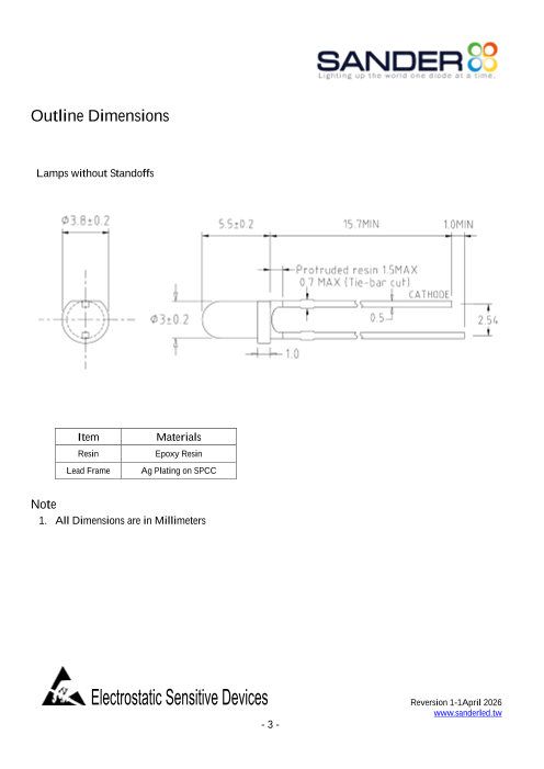
Outline Dimensions
Lamps without Standoffs
Item Materials
Resin Epoxy Resin
Lead Frame Ag Plating on SPCC
Note
1. All Dimensions are in Millimeters
Reversion 1-1April 2026
www.sanderled.tw
- 3 -
Electrical-Optical Characteristics
1.6
1.4
1.2
1.0
0.8
0.6
0.4
0.2
0.0
0 5 10 15 20 25 30
35 1.2
TA=25℃
30 1.0 IF=20mA
25
0.8
20
0.6
15
0.4
10
5 0.2
0 0.0
0 20 40 60 80 100
300 400 500 600 700 800
Reversion 1-1April 2026
www.sanderled.tw
- 4 -
Soldering Conditions - Lamp Type LED
Solder the LED no closer than 3mm from the base of the epoxy bulb. Soldering beyond the base of
the tie bar is recommended
Recommended soldering conditions
Dip Soldering
Pre-Heat 100℃ Max.
Pre-Heat Time 60 sec. Max.
Solder Bath Temperature 260℃ Max.
Dipping Time 5 sec. Max.
Dipping Position No lower than 3mm from the base of the epoxy bulb.
Hand Soldering
3Ø Series Others (Including Lead-Free Solder)
300℃ Max. 350℃ Max.
Temperature
Soldering time 3 sec. Max. 3 sec. Max.
Position No closer than 3mm from No closer than 3mm from
the base of the epoxy bulb. the base of the epoxy bulb.
Do not apply any stress to the lead, particularly when heated
The LEDs must not be repositioned after soldering
After soldering the LEDs, the epoxy bulb should be protected from mechanical shock or vibration
until the LEDs return to room temperature.
Direct soldering onto a PC board should be avoided. Mechanical stress to the resin may be caused by
the PC board warping or from the clinching and cutting of the leadframes. When it is absolutely
necessary, the LEDs may be mounted in this fashion, but, the User will assume responsibility for any
problems. Direct soldering should only be done after testing has confirmed that no damage, such as
wire bond failure or resin deterioration, will occur. Sander’s LEDs should not be soldered directly to
double sided PC boards because the heat will deteriorate the epoxy resin.
When it is necessary to clamp the LEDs to prevent soldering failure, it is important to minimize the
mechanical stress on the LEDs.
Cut the LED leadframes at room temperature. Cutting the leadframes at high temperatures may
cause LED failure.
Reversion 1-1April 2026
www.sanderled.tw
- 5 -