

高い生産性と優れた操作性を実現
歯車製造において、高い加工精度と品質を維持しながら、生産性と効率性を向上させることは重要な課題です。
KlingelnbergのHöfler円筒歯車研削盤「Speed Viper」は、高精度かつ効率的な円筒歯車研削加工を実現し、高品質な歯車製造をサポートします。
Klingelnbergは、長年培ってきた歯車加工技術と専門知識を活かし、歯車の設計から製造、品質保証までを一貫して支援するクローズドループソリューションを提供しています。
ソフトウェア「Gear Designer」と「Gear Operator」は、デジタルツインを活用した製造工程のシミュレーションを可能にし、歯車の設計・加工プロセスの最適化を支援します。
Speed Viperは、先進的な円筒歯車研削技術を通じて、自動車産業をはじめとするさまざまな分野の歯車製造における高精度・高効率な生産に貢献します。
◆詳細はカタログをダウンロードしてご覧いただくか、お気軽にお問い合わせください。
関連メディア
このカタログについて
| ドキュメント名 | HÖFLER 円筒歯車研削盤 Speed Viper |
|---|---|
| ドキュメント種別 | 製品カタログ |
| ファイルサイズ | 2.8Mb |
| 登録カテゴリ | |
| 取り扱い企業 | 日本クリンゲルンベルグ株式会社 (この企業の取り扱いカタログ一覧) |
この企業の関連カタログ

このカタログの内容
Page1
HÖFLER
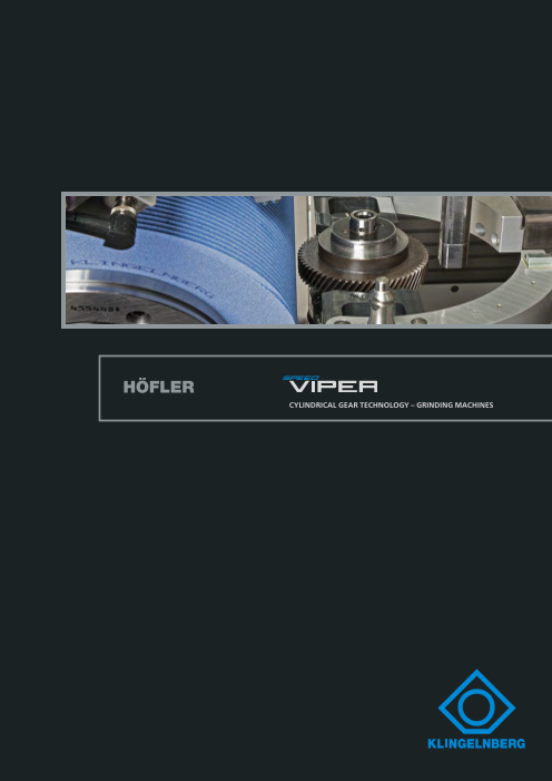
CYLINDRICAL GEAR TECHNOLOGY – GRINDING MACHINES
Page2
LEADING IN CYLINDRICAL GEAR TECHNOLOGY
Innovative Cylindrical Gear Machining
for Flexible Requirements
All around the world, manufacturers of gears and gear-
boxes ensure their leading edge in gear machining
with innovative, advanced technology by Klingelnberg.
The Höfler Cylindrical Gear Technology division allows us-
ers to manufacture cylindrical gears with diameters from
20 millimeters up to 10 meters economically and with
high precision. Moreover, thanks to decades-long exper-
tise and great innovative strength, Klingelnberg is able to
maintain a leadership position not only through its high
research and development standards, but also its in-house
application engineering services.
Klingelnberg offers advanced technology and efficient
machines for cylindrical gear manufacturing. The com-
Winner of the iF Design
pany sees itself as a solutions provider that supports its Award 2018
customers from gear design to quality assurance, in order
to produce top quality gearing. Klingelnberg’s software
system for production management from process design
to quality control is called Closed Loop – and is now also
available for cylindrical gears.
Its core component is the powerful duo, Gear Designer
and Gear Operator – two newly developed soft-
ware solutions that accurately simulate the entire
manufacturing process using a digital twin of the
workpiece to be ground, providing optimal sup-
port for gear design and manufacturing.
Höfler cylindrical gear machines are developed
with real-world applications in mind and satisfy a
whole host of application industry requirements.
Customers include all gearbox manufacturers in
the precision engineering, aviation and automo-
tive industries, as well as manufacturers of large
gears for the energy industry.
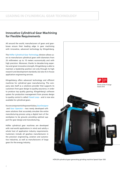
HÖFLER cylindrical gear generating grinding machine Speed Viper 300
2
Page3
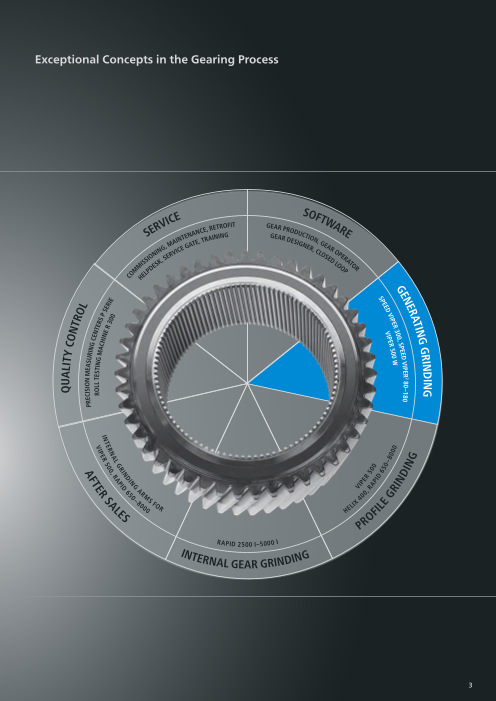
Exceptional Concepts in the Gearing Process
so
Ice ft
fIt g w
e
e, retro Ar Pro A
serv
d
nAnc ge u r
ctI
Inte Ar d
te, trAInIng
e o e
sI n
,
g
, M
A gn
e gA
er e
, A
c r
nIng
rvIc lo o
s P
Io , se
ed e
r
ss
sk
l A
o t
de o o
lP
P r
MMI
he
Ar
M
0– s
8 4
0 f
0 o lIx
e 0 r
s
he
of
P
r
r
A I
PId
2500 I–5000
Inter
nAl geAr grIndIng
3
QuAlItY con
trol
sIon MeA
Pr
ecI surIng
cent e
rs
roll testIng MAch P
I
n s
e
e
r r
3
I
0 e
0
c
o
v
0 I0 P
, e
r r 5
I A
P 0
l I 0
e d
6
g 50
r –80
I 0
n 0
dIng
ndIng
tIng
grI
ner
A
Per2 80–180
ge 00, sP
eed vI
er 3 w
vIP
IPer 5
00
v
sPee
d
g
In
nd 65
Id
Al g
rI
AP l
rn 0,
r
Int
e
r 5
0
vIP
e r sA
te
Af
Page4
OUTSTANDING GRINDING TECHNOLOGY
The New Force in High-Productivity
Generating Grinding
The Höfler cylindrical gear grinding machine Speed Viper –
which focuses on high-productivity generating grinding in
large-series manufacturing – draws on the successful concept Highly productive generating
of the Viper 500 series. It is available in four different configu- grinding thanks to intelligent ma-
rations based on individual requirements: Speed Viper 300 in a chine software and a robust ma-
single-spindle configuration, as well as Speed Viper² 180 and
chine base
80 in a dual-spindle configuration. Depending on the model,
Speed Viper is designed for maximum workpiece diameters
of 80, 180 and 300 mm. In addition to gears, it can also grind Large component range to 300 mm
extra-long shafts. This is possible thanks to a distance between workpiece diameter and 1,100 mm
centers over table of up to 1,100 mm. workpiece length
The Speed Viper² dual-spindle concept achieves minimal auxil- Long tool life thanks to large tool
iary times, fulfilling the productivity requirements of the auto-
motive industry. The grinding worms, with an outside diameter diameters of 275 (320) mm and a
of 275 (320) mm and a width of 200 mm, ensure a long tool life. tool length of 200 mm
An automatic tool clamping system with an integrated balanc-
ing unit also contributes to shortened tooling times as an op- Minimal auxiliary times
tion. In addition, the Speed Viper with partial or full automa-
tion can be equipped with an automation interface that meets Flexible automation concept
the VDMA 34180 and ISO 21919 standard.
Innovative operating concept
The Gear Operator machine software and a process-oriented
navigation system via wizard technology make operation easy, Optimal energy efficiency (e2)
even in the most complex applications. And last but not least,
ultra-modern drive and control technology guarantees maxi- Short set-up times thanks to auto-
mum energy efficiency.
matic tool clamping system (opti-
nal)
Z1 CNC axes
C4
Z2 Speed Viper 300 Speed Viper² 180/80
B2 X Radial axis X Radial axis
B2
C2 Y Shift axis Y Shift axis
C3 Z Stroke axis Z Stroke axis
Z3 Z1 Counter support Z1/Z2 Counter support
C5 A Swivel grinding head A Swivel grinding head
B Grinding spindle B Grinding spindle
B2 Dressing spindle B2 Dressing spindle
C Workpiece spindle C1/C2 Workpiece spindle
C3 Dressing device swivel C5 Rotating tower
Speed Viper 300 Swivel loader Speed Viper2 80 C4 Loader swivel
Z3/Z4 Loader stroke axes
4
Page5
Speed Viper – More Than Just a Generating Grinding Machine
Generating Grinding
Maximum productivity at cutting speeds up to 100 m/s
Polish Grinding (optional)
Efficient gearing through the use of segmented tools
with a total width of 200 mm
Topological Grinding (optional)
Grinding of twist-free tooth flanks as well as targeted
twists, incl. Closed Loop processing
Beveloid Gearing (optional)
Grinding of beveloid gearing, with freely definable flank
modifications as needed for improved running behavior
and optimized load carrying capacity
5
Page6
HIGHLIGHTS
Speed Viper is fit for Industry 4.0
Bevel Gear Technology
for Mass-Production of “The gear cutting industry is in transition” – and Klingelnberg is poised to em-
brace the challenges ahead. The Speed Viper development team, consisting of
Cylindrical Gears engineers from the bevel gear and cylindrical gear product lines, has developed a
unique machine design that combines know-how from the OERLIKON Bevel Gear
Manufacturing cylindrical gears Technology and HÖFLER Cylindrical Gear Technology brands. Thus Speed Viper
on a large scale – for Klingelnberg, combines outstanding grinding technology and an innovative operating concept
this meant taking technology with the unique Klingelnberg Closed Loop process. The structural design of the
and expertise from bevel gear machine is based on experiences gleaned from the successful C 30 and G 30 bevel
production and applying it to gear machines as well as the VIPER 500 cylindrical gear machine. Speed Viper’s
the cylindrical gear industry. The success factors include:
result from the interdisciplinary High productivity High quality thanks to Maintenance-friendly
development team is reflected in through minimal rugged mechanical machine design com-
Speed Viper: productive time and engineering and the bined with expert service
auxiliary time Klingelnberg Closed
Systematic linking of gear Loop concept
design and production
Integration of Speed Viper
into the Klingelnberg produc-
tion system
Use of the Closed Loop system,
which has been proven the
world over for bevel gears, for
cylindrical gears
Result:
Speed Viper uses bevel gear DNA
for large-scale production of
acoustically optimized cylindrical
gears.
HÖFLER generating grinding machine Speed Viper 300 with CompactLoader
Innovative Machine Design for Maximum Productivity
Cutting speeds up to 100 m/s
Rugged machine design, made of vibration-damping cast polymer
Optimal automation capability for minimal auxiliary times
Use of long-life tools
Compact design with minimal travel paths in the process
High-performance, aerodynamic nozzle for efficient coolant supply
6
Page7
Maximum Flexibility in the Grinding Process
Speed Viper platform covers a broad range of components (large
travel paths)
Integrated, automated configuration of table drive parameter based
on workpiece inertia
Tool diameters between 210 mm and 275 (320) mm
Thermally stable machine design
Flexible automation interface
Automatic tool clamping system for minimal set-up times (optional)
Convenient, Intuitive Operating Concept
Systematic linking of gear design and production
Intuitive operator guidance through user-oriented operating concept
and easy-to-follow menu design
Modern control panel with touchscreen display and clear screen lay-
out
Integration of Klingelnberg Closed Loop system
Analysis, planning and control functions in parallel with production
time, thanks to multitasking capability of Gear Operator software
Machine configuration successfully completed in just a few steps
Easy, Fast and Service-friendly Maintenance
Rugged design of machine components
Pivoting control cabinet
Logical arrangement of power supply
Easy accessibility of modules to be serviced
Real-time remote maintenance via Ethernet connection
7
Page8
HIGHLIGHTS
Acoustically Optimized Cylindrical Gears in
Large-scale Production
Linking of gear design with production for acoustically optimized
gears
Rugged machine base (large guide width) for minimal gearing devia-
tions in the process
Dynamically optimized drives
Two-plane balancing system for minimal excitation in the process
Systematic implementation of the Klingelnberg Closed Loop system,
which provides feedback to the grinding machine about the manu-
factured quality
Closed Loop Quality Control in Line with Industry 4.0
Central gearing and process design
Networked connection in the Klingelnberg production system
(GearEngine®)
Knowledge management with central production data acquisition
Digitization of gear production through automated machine correc-
tion
Energy Efficiency (e²) for Maximum Savings
Flow-optimized coolant supply
Pressure sensor on high-performance nozzle for fastest possible pro-
cess start, as soon as adequate coolant is available
On-demand optimization of drive control for permanent reduction of
energy loss
Systematic gear design with testing of producible geometries allows
production of ultra-precise tooth geometries for optimized gear run-
ning behavior
8
Page9
Gear Operator – Process-oriented Operator Guidance with
Wizard Technology
Powerful and Reliable
Reproducible quality through central manage-
ment of relevant tool and process parameters
Maximum productivity through custom machin-
ing and loading cycles
Workpiece and device-dependent axis drive opti-
mization
Process analysis and control in parallel with grind-
ing using independently operated control and
display pages
Collision management based on a dynamic 3D
machine model
Automated quality control in Klingelnberg
Closed Loop system
Convenient and Clearly Laid-out
Siemens Sinumerik One control unit with touch-
screen display
Intuitive user interface with process-oriented
operator guidance
Clarity through constantly visible menu struc-
ture and immediately responsive program logic
Convenient setup with customized configura-
tion of operating sequences
Effective context-sensitive help with text, image
and video material
Flexible and Expandable
Enhanced process reliability: Service and maintenance: Technologies:
Digital identification of tools Remote maintenance via Finish grinding and polishing
and clamping fixtures Klingelnberg Service Gate
Topological grinding of specific
Automatic allowance and stock Comprehensive machine and twists
removal control process analysis with Gear
Analyzer Generation grinding of
Contact monitoring during beveloid gearing
dressing Preventive maintenance with
automatic axis test
9
Page10
USER-FRIENDLY SOFTWARE CONCEPT
Real Productivity Gains with
Gear Designer and Gear Operator
The quality demands on transmissions and gears continue Gear Designer imports the “function-oriented gear geometry”
to increase. Masking noises in the transmission environ- defined by the design engineer and carries out a production
ment – such as noise from the combustion engine – are di- simulation. The resulting “production-ready gear geometry”
minishing or are being eliminated altogether as in the is determined, taking the tool geometry and process kinemat-
electric drive. Add to these the demands on transmission ics into account. This is then analyzed and further optimized
engineers to develop designs that are as resource-efficient by the design engineer. Once the “process-ready gear ge-
as possible. Lightweight design and the use of low-viscosity ometry” has been approved, it is transferred to GearEngine®
transmission oil mean that gear quality must improve in or- and the central management there. Gear Operator loads the
der to achieve comparable or improved acoustic behavior. data record and interactively assists machine operators in
their tasks. In-series optimization of the gear geometry takes
In transmission and gear design, the use of calculation soft- place via the Closed Loop quality control process. Gear varia-
ware for tooth contact analysis is commonplace. Optimiza- tions are identified relative to the approved “production-
tion of gear modifications involves the elastic behavior of ready gear geometry,” and the process is corrected accord-
the shaft bearing system. In many cases, the gear geometry is ingly. This follows the Klingelnberg philosophy that has been
optimized by simulating many variants, taking the tolerance used successfully in bevel gear production for many years.
fields into account. The objective of this variation calculation
is to define a gear that is as rugged as possible. Result: A virtual twin is created, which provides an achievable
image for every process step. This makes it possible to clealy
Klingelnberg has come up with a software package that analyze deviations and identify the causes. It also eliminates
draws on its successful production system for bevel gears. uncertainties in the machine and cutter head setting and
Gear Designer and Gear Operator are unique software solu- checking device with regard to the achievable quality and the
tions that were developed to implement the Closed Loop pro- quality actually achieved.
cess for cylindrical gears.
The first Closed Loop is located at the interface between
transmission calculation and production engineering.
10
Page11
The Speed Viper Concept
Gear Operator
GearEngine®
Data management
Machine settings Nominal data & tolerances
Correction data Gear Designer Measured values
Producible gear geometry
Function-oriented gear geometry
www.speedviper.com
11
Page12
EXPERTISE IN COUNTLESS INDUSTRIES
Automotive Industry in Transition
“Electromobility” and “Industry 4.0” are hot topics currently sion concepts, but also to significantly increased demands on
under discussion in the automotive industry. As an automotive the vibration and noise characteristics of the transmission.
supplier, Klingelnberg is also tackling these issues, in an effort Whereas input speeds in IC engine-powered passenger cars
to develop specific solutions for the demands of the future. do not exceed 6,000 rpm in most cases, motors with speeds
significantly greater than 20,000 rpm are used in the electric
Demands on the automotive industry: powertrain. This brings gear runout and cumulative pitch er-
Owing to the characteristics of the speed-torque curve rors – previously only significant as the cause of side bands or
in the electric motor, it is possible to adapt the product tooth mesh harmonics – into the acoustically relevant range.
range to suit the tractive power requirement curve in ve-
hicles using fewer gears than is the case with the combus- Klingelnberg solution:
tion engine. But industry professionals all agree that gear With GearEngine® and its Closed Loop approach, Klingelnberg
transmissions will continue to be indispensable, even in an has developed a exceptional solution for the process chain in cy-
electrified powertrain. This is necessary to meet require- lindrical gear manufacturing. Owing to the quality-determining
ments for driving comfort, efficiency and vehicle costs. influence of hard finishing, the networking of Speed Viper with
the Klingelnberg Precision Measuring Centers is a crucial step in
Current electric drive concepts for passenger cars frequently ensuring the quality of the production process. With the analy-
comprise of an electric motor with single-shift transmissions, sis options of the P machine software, particularly the waviness
consisting of two cylindrical gear stages or one plane- analysis option, the causes of noise problems can be quickly pin-
tary stage and one cylindrical gear stage. In light- pointed. Thus the right tools are available for automotive gear
weight commercial vehicles, concepts with production – and not just for electric powertrain transmissions.
up to two shifts are used, and the starting
point in heavy-duty commercial Conclusion:
vehicles is currently six to eight Klingelnberg solutions deliver useful tools for gear produc-
shifts, which are shifted au- tion in the automotive industry of today and tomorrow, thus
tomatically via the drive providing the right answers to questions arising in the areas of
control based on the “electromobility” and “Industry 4.0”.
driving situation.
The elimination of
the internal com-
bustion engine will
lead not only to
changes in transmis-
12
Page13
Commercial Vehicles
The developments in commercial, construction, and ag-
ricultural vehicles have never been as exciting: Specific
industry solutions, payload optimization, sophisticated
safety systems and not least fuel efficiency are just a few of
the key trends. Each new vehicle generation must fulfill the
requirement of providing more safety and comfort while
achieving lower total overall operating costs. The use of
Klingelnberg solutions makes it possible to mass-produce
cylindrical gears with the required quality.
Contract Gear Manufacturers
Contract gear manufacturers in particular have to be able
to react flexibly to market conditions on a daily basis and
produce a whole host of different gear components. From
standard solutions to high-tech applications – Klingeln-
berg offers its customers tailor-made machine designs.
These are supplemented by comprehensive engineering
and other services, including everything from in-house
machine certification at Klingelnberg, to machine-atten-
dant and software training, right through to production
support.
Industrial Gear Units
The industrial gear unit sector comprises many different
applications, all of which place great demands on the reli-
ability of gear wheels. The cylindrical gears for these sec-
tors are often produced by companies specializing in small
batch sizes and a variety of products. A rigid machine de-
sign and flexible, cost-effective tool systems are the keys
to success for ranking among the market leaders in these
sectors.
Robot Industry
Digitization, automation, and robotics are key issues in
mechanical and plant engineering. From the autonomous
lawn-mower to the articulated robot in the operating
room: In addition to sophisticated software, every robot
runs on high-precision hardware – and that starts with
the smallest toothed gear. With Klingelnberg system solu-
tions for cylindrical and bevel gears, the right “mechanical
backbone” for every robot type can be built in the smaller
diameter ranges.
13
Page14
TECHNICAL DATA
SPEED VIPER 300 SPEED VIPER2 180 SPEED VIPER2 80
Workpiece diameter (max.) Ø 300 mm Ø 180 mm Ø 80 mm
Grinding stroke 500 mm
Distance between center above table
370 – 1,100 mm 295 – 895 mm
(min. – max.)
Module (min. – max.) (0.5) 1 – 5 mm (0.5) 1 – 3 mm
Swivel angle +/- 45°
Grinding worm diameter Ø 200 – 275 (320) mm
Grinding worm width (max.) 200 mm
Grinding spindle 25 kW
Grinding worm speed 7,200 rpm
Cutting speed 100 m/s
Table diameter Ø 180 mm Ø 120 mm
Table load (max.) 50 kg 35 kg
Table hole (diameter x depth) Ø 87 x 196 mm Ø 59 x 150 mm
Table rotation speed (max.) 2,300 rpm 3.000 min-1
Axial feed rate 12,000 mm/min
Total connected load 40 kVA
Machine dimensions (L x W x H) approx. 3,085 x 2,160 x 3,420 mm approx. 3,455 x 2,160 x 3,420 mm
Filter unit dimensions (L x W) approx. 3,400 x 2,160 mm
Net weight approx. 16,500 kg approx. 18,500 kg
The dimensions of the standard version are for orientation only. Swivel ranges for doors, operating panels etc. are not taken into account here. The final space requi-
rement depends on the individual configuration of the machine.
14
Page15
Installation Dimensions
SPEED VIPER 300 SPEED VIPER2 180 SPEED VIPER2 80
SPEED VIPER 300: FRONT VIEW
Workpiece diameter (max.) Ø 300 mm Ø 180 mm Ø 80 mm
Grinding stroke 500 mm
Distance between center above table
370 – 1,100 mm 295 – 895 mm
(min. – max.)
Module (min. – max.) (0.5) 1 – 5 mm (0.5) 1 – 3 mm
Swivel angle +/- 45°
Grinding worm diameter Ø 200 – 275 (320) mm
Grinding worm width (max.) 200 mm
Grinding spindle 25 kW
Grinding worm speed 7,200 rpm
Cutting speed 100 m/s
Table diameter Ø 180 mm Ø 120 mm
SPEED VIPER 300: TOP VIEW
Table load (max.) 50 kg 35 kg
Table hole (diameter x depth) Ø 87 x 196 mm Ø 59 x 150 mm
Table rotation speed (max.) 2,300 rpm 3.000 min-1
Axial feed rate 12,000 mm/min
Total connected load 40 kVA
Machine dimensions (L x W x H) approx. 3,085 x 2,160 x 3,420 mm approx. 3,455 x 2,160 x 3,420 mm
Filter unit dimensions (L x W) approx. 3,400 x 2,160 mm
Net weight approx. 16,500 kg approx. 18,500 kg
All dimensions in mm
15
Page16
BEVEL GEAR TECHNOLOGY I CYLINDRICAL GEAR TECHNOLOGY I MEASURING TECHNOLOGY I DRIVE TECHNOLOGY
KLINGELNBERG Service
The KLINGELNBERG Group is a world leader in the development and manufacture of
machines for bevel gear and cylindrical gear production, and precision measuring centers
for gearing and axially symmetrical components, as well as the production of customized
high-precision drive components. In addition to the headquarters in Zurich, Switzerland,
further development and production facilities are located in Hückeswagen and Ettlingen,
Germany.
The company also maintains a presence with Sales and Service offices and numerous
marketing agents. On this basis, Klingelnberg offers users a comprehensive range of
services for all aspects of toothed gear design, manufacturing, and quality inspection.
The spectrum includes technical consulting, on-site machine acceptance, operator and
software training as well as maintenance contracts.
KLINGELNBERG Solutions
Klingelnberg solutions are used in the automotive, commercial vehicle, and aviation
industries, as well as in shipbuilding, the wind power industry, and the general transmis-
sion manufacturing industry. With numerous R&D engineers around the globe and over
200 registered patents, the company consistently demonstrates its capacity for innovation.
FOLLOW US AND STAY UP TO DATE:
KLINGELNBERG AG KLINGELNBERG GmbH KLINGELNBERG GmbH
Binzmühlestrasse 171 Peterstraße 45 Industriestraße 5–9
8050 Zürich, Switzerland 42499 Hückeswagen, Germany 76275 Ettlingen, Germany
Fon: +41 44 278 7979 Fon: +49 2192 81-0 Fon: +49 7243 599-0
Fax: +41 44 273 1594 Fax: +49 2192 81-200 Fax: +49 7243 599-165
You can also find your local contact for sales advice at https://klingelnberg.com/en/contact
WWW.KLINGELNBERG.COM • INFO@KLINGELNBERG.COM 16
EN 03/2025 - Subject to technical modifications without notice.