


余分な配線を一切排除し、今までにないシンプルなシステムの構築が可能となりました。
世界最小の一体型ACサーボシステム誕生!
クールマッスル2(CM2)はモータ・エンコーダ・ドライバ・コントローラ・PLC機能・電源ユニットの全てを内蔵した「一体型ACサーボシステム」。
余分な配線を一切排除し、今までにないシンプルなシステムの構築が可能となりました。省スペース、省配線、コスト削減、開発時間の短縮に貢献します。
◆モータ
ACサーボモータをベースに定格回転数6,000min、最高回転数8,000minの高回転が可能となりました。(機種による)
◆エンコーダ
自社開発の高精度磁気エンコーダ搭載により、50,000分解能、静粛でスムーズな動作や高精度位置決めを実現。
◆ドライバ/電源内蔵
クローズドループベクトル制御を搭載し、制御/動力電源まで内蔵。 モータ線が内蔵されているため発生ノイズが軽減されます。
◆詳細は、カタログをダウンロードしてご覧ください。
◆不明点があればお電話にてお気軽にお問合せください。
関連メディア
このカタログについて
| ドキュメント名 | 一体型ACサーボシステム クールマッスル2 モータ・エンコーダ・ドライバ・コントローラ・PLC・電源内蔵 |
|---|---|
| ドキュメント種別 | 製品カタログ |
| ファイルサイズ | 28.4Mb |
| 登録カテゴリ | |
| 取り扱い企業 | マッスル株式会社 (この企業の取り扱いカタログ一覧) |
この企業の関連カタログ


このカタログの内容
Page1
表紙_ 17501B(CM2差替)
2010年上海万国博覧会 日本産業館 「夢ROBO」に「クールマッスル2」搭載
“COOL MUSCLE 2”, used in “YUME ROBO” at 2010 Shanghai Expo - Japan Industry Pavilion
Designed by Toshiyuki KITA
Produced by Muscle Corporation
I n t e g r a t e d A C S e r v o S y s t e m
Motor
Encoder
Driver
Controller
PLC
Power Supply
All in ONE Solution
Page2
p01-170501
Motor
Encoder
Driver
Controller
PLC
Power Supply
Encoder
Messy Motor
Power Supply
PLC Huge
Heavy
Driver
Controller
1
Page3
p02(CM2差替)170501
Compact
like me
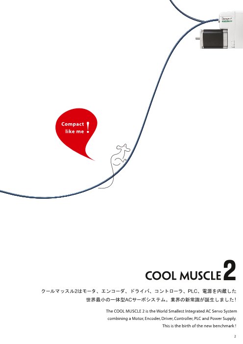
クールマッスル2はモータ、エンコーダ、ドライバ、コントローラ、PLC、電源を内蔵した
世界最小の一体型ACサーボシステム。業界の新常識が誕生しました!
The COOL MUSCLE 2 is the World Smallest Integrated AC Servo System
combining a Motor, Encoder, Driver, Controller, PLC and Power Supply.
This is the birth of the new benchmark !
2
Page4
p03-170501
PLC機能
数値/論理演算可能
PLC Function
Arithmetic/ Logical operation
コントローラ
All in One Solution トルク制御、独自OS搭載、補間動作(オプション)
Controller
Torque control, Proprietary OS, Interpolation function(option)
ドライバ
クローズドループ正弦波ベクトル制御、チューニングレス
Driver
Closed-loop sinusoidal vector control, Tuningless
電源
AC100-240V対応、コンセントに直接接続可能
Power Supply
Direct connection to AC100-240V
通信
RS-232Cを2ポート装備
デイジーチェインで多軸化
Communication
Two RS-232C ports, multi-axis
network with the daisy chain
モータ
ACサーボモータ
入出力(I/O)
Motor
デジタル入力6点/デジタル出力4点
AC servo motor
アナログ入力1点/アナログ出力1点
Input/Output (I/O)
6 Digital Inputs/4 Digital Outputs
1 Analog Input/1 Analog Output
エンコーダ
磁気エンコーダ搭載、50,000分解能
Encoder
Magnetic encoder, 50,000ppr
3
Page5
p04-170501
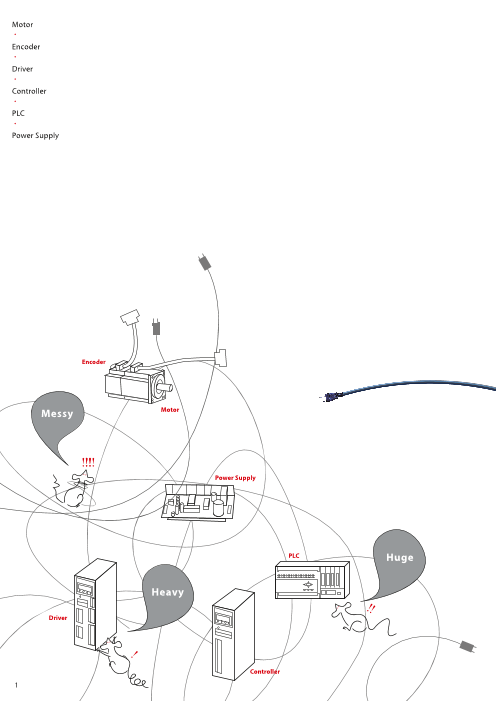
従来のシステム例 クールマッスル2のシステム例
Conventional system example COOL MUSCLE 2 system example
プログラマブル
ディスプレイ ターミナル
Programmable
Display Terminal
プログラマブル
ディスプレイ ターミナル
Programmable
Display Terminal
PLC
PLC
コントローラ
Controller
電源へ
To Power Supply
クールマッスル2
COOL MUSCLE 2
サーボドライバ
Servo Driver
電源へ 電源へ
To Power Supply To Power Supply
サーボモータ
Servo Motor
4
Page6
p05(CM2差替)170501
Features クールマッスル2の特長
世界最小の一体型ACサーボシステム誕生! The World Smallest Integrated AC Servo System !
クールマッスル2(CM2)はモータ・エンコーダ・ドライバ・コントローラ
COOL MUSCLE 2(CM2) is an “Integrated AC
・PLC機能・電源ユニットの全てを内蔵した「一体型ACサーボシス
テム」。 Servo System” combining a Motor, Encoder, Driver,
余分な配線を一切排除し、今までにないシンプルなシステムの構築 Controller, PLC function and Power Supply into one
が可能となりました。省スペース、省配線、コスト削減、開発時間の fully integrated package.
短縮に貢献します。 Allowing for space saving, wiring and cost reduction,
and also shorten development time.
モータ + エンコーダ + ドライバ
Motor Encoder Driver
電源 + コントローラ + PLC
Power supply Controller
01 01. Motorモータ
AC Servo motor speed rated at 6,000min-1, with maximum
ACサーボモータをベースに定格回転数6,000min-1、最高回転数8,000min-1の
speed of 8,000min-1 . (Speed depend on model)
高回転が可能となりました。(機種による)
02 エンコーダ The proprietary magnetic encoder provides a resolution of
自社開発の高精度磁気エンコーダ搭載により、50,000分解能、静粛でスムー 50,000ppr and high precision positioning with smooth and
ズな動作や高精度位置決めを実現。磁気エンコーダの為、悪環境での使用や
quiet motion. The magnetic encoder will not be a ected by
経年変化に対する不安がありません。
harsh environmental conditions or age softening.
03 03. Integrated Driver/Power Supplyドライバ/電源内蔵
CM2 is an AC servo system incorporates an enclosed
クローズドループベクトル制御を搭載し、制御/動力電源まで内蔵。 モータ線が
closed-loop vector controller and control/drive power supply.
内蔵されているため発生ノイズが軽減されます。またAC100-240Vまで切換える
ことなく電源に直接接続可能。(60A20, 60A40はAC200-240V限定) All motor wiring is hidden minimizing any potential emitted
motor noise and can be powered by simply connection to an
■ チューニングレス
AC100-240V. No AC conversion is required.
現代制御理論を応用した独自の制御技術によって、サーボゲインのチューニ
(60A20, 60A40 accept only AC200-240V)
ングレスを実現しました。サーボ特有の煩わしいゲイン調整から解放され、一
定範囲の負荷に対して安定した動作を実現します。ゲイン調整がなくなること
によって作業時間を大幅に削減できます。
5
Page7
p06-170501
04 コントローラ 04. Controller
Easy parameter setting and programming of various
各種パラメータ設定、基本動作から複雑な動作まで様々な動作プログラムを簡単に
motions.
作成することができます。
CML ■ CML■
CML(COO L MUSC LE Language)は、クールマッスル専用のプログラミング言語です。 CML (COOL MUSCLE Language) is a programming
専用ソフトのクールワークスライト、ハイパーターミナルを使用して簡単にプログラムを language designed for CM2. Using CML can simplify
組むことができます。動作の実行はCMLコマンド、またはスイッチでも可能です。 any programming with COOL WORKS LITE or Hyper
Terminal. Programmed motion can be executed by
簡単パラメータ設定 Easy Parameter setting CML commands or simple switches.
K20.1 = 0 通信ボーレートを38.4kbpsに設定
Set Communication Baud Rate to 38.4kbps
K46.1 = 1 電源オン時メカストッパ押し当て原点復帰開始
Power on and start origin search automatically ■ Easy to Use
by pushing mechanical stopper.
[Direct Mode]
CM2 can be directly operated by simply entering CML
■ 簡単操作
commands via RS-232C communication.
[ダイレクトモード]
RS-232C通信を使いCMLコマンドを入力するだけで直接モータを動作させることが
[Program Mode] (P type Excluded)
可能です。
Since programs can be downloaded to CM2, various
ダイレクトモード例 Direct mode example motions can be executed by PC or simple switches.
パソコンを使って
S.1 = 250 速度設定 ダイレクトに実行
Set speed Direct operation
A.1 = 100 加速度設定 by PC
Set acceleration
P.1 = 10000 目標位置設定
Set target position
^.1 実行
Execute
[プログラムモード](Pタイプを除く)
プログラムをダウンロードすることが可能なため、様々なプログラム動作をスイッチ
やパソコンにて簡単に実行できます。
1.動作定義 Define motion Easy
P1.1 = 1000
P2.1 = 3000 速度(S)、加速度(A)、
P3.1 = - 1000 位置(P)、タイマー(T)の
S1.1 = 100 動作定義
S2.1 = 300 Speed(S),acceleration(A),
A1.1 = 50 position(P) and timer(T)
are the motion definition.
T1.1 = 100
2.プログラム Program スイッチ操作で
先に定義された速度、 プログラム実行B1.1 Execute programs
A1.1 , S1.1 , P1.1 加速度、位置、 by switches
A1.1 , S2.1 , P2.1 タイマー等を使って
T1.1 プログラムを組みます。
S1.1 , P3.1 Define motion programs using
the motion profiles defined above.
6
Page8
p07-170501
Features クールマッスル2の特長
■ 多種多様な動作 ■ Wide Variety of Motion
CM2は基本的な動作から複雑な動作まで様々な動作パターンをサポートします。 CM2 supports standard motion control, as well as, a wide
variety of custom programmed movements.
[PTP動作]
[Standard PTP]
加速度、減速度をそれぞれ自由に設定可能。速度、加速度をモータ動作中に
Both acceleration and deceleration can be independently set.
任意に変化させたり、通過点で一時停止することなしに速度、加速度を変化さ
Also various methods of PTP motion such as speed and
せる(マージ動作)等、様々なPTP動作が可能です。
acceleration changes during motion at passing points
基本PTP Standard PTP
Speed without stopping or jittery movement, (Merge Motion) can
S2 be realized.
A1 A1
S1 P3
A1 A1 A1 A1
P1 P2
Time
T1 T1
マージ動作 Merge Motion
Speed
S3 CM2 can continuously push at a set torque rate for the set
A2 A2
S2
A1 time period, replacing pneumatic cylinders and grippers. This
P3
S1 P2
A1 exible torque control is adaptable for multiple systems and
P1
Time use.
加・減速が異なるPTP PTP with different acceleration and deceleration
Speed
S1
A1 A2
P1 P2
Time
[トルク制御]
● 押付け動作
設定されたトルクで、設定された時間押付け動作が可能です。エアシリンダ、
エアチャックからの置換えができます。自在なトルク制御によって様々なシステ ● Torque Feedback
ムに対応可能です。 CM2 supports torque feedback control with an external torque
Speed
S3 sensor, which automatically changes the output torque
A1 A1
according to the sensor signal. This feature is an ideal solution
S1
P1 P2 for applications that require constant tension such as pulling
0
Time machines.
Torque
Torque limit set by Parameter
トルク制限値パラメータで設定
Pushing
0
Time
Time duration set by Parameter
保持時間パラメータで設定
Push Motion
● トルク制限
動作時の出力トルクを制限する事が可能です。設定トルク以下で動作するので、
搬送などのアプリケーションに最適です。
● トルクフィードバック
外部トルクセンサをつないでのトルクフィードバック制御が可能な為、外部から
の信号に応じて出力トルクを自動的に変更できます。一定力での引き出し機械、
テンション一定制御などのアプリケーションに最適です。
7
Page9
p08-170501
[補間](オプション) [Interpolation] (Optional)
円弧/直線補間を3つのコマンドだけで簡単に実行できます。補間機能が内蔵されている為、 Circular and linear interpolation can be executed
外部に補間ユニットは必要なく、開発時間やコストを大幅に削減する事が可能です。 with only 3 commands. This function is
integrated into the CM2, eliminating the need for
終点
End point
an external interpolation unit and dramatically
始点
Start point R半径
@+ Radius @- shortening development time.
N中心点 終点
Center point End point
始点 コマンド 機能 Function
Start point R 半径設定 Radius setting
N 中心点設定 Center setting
@ 実行 Execution
■ 演算機能
プログラム内で数値演算、論理演算が可能です。定義されたデータやモータの位置、速度、 logical operation
I/Oなどの情報を用いた演算を行いながら複雑な制御を可能にしました。値の大小比較や
論理演算による条件分岐など、演算機能を使うことでモーション制御の幅が更に広がります。
1.動作定義 Define motion
V1.1 = "Px" データ定義(Px:モータの現在位置)
V2.1 = 10000 Data definition(Px:Current Position)
2.プログラム Program
B1.1 先に定義された値を使って条件分岐プログラムを
V1.1 >V2.1,O1.1,O2.1 組みます。
?96.1 Conditional Branch Processing
プログラムバンク1 スタート
Beginning of ProgramBank1
V1>V2 V1とV2の定義値を比較 V1≦V2
Compare V1 with V2
O1.1 実行 O2.1 実行
Execute O1.1 Execute O2.1
?96.1実行
Execute ?96
■ ティーチング機能
ティーチングペンダントを使用せず位置のティーチングが可能。コマンドまたは入力信号
によって現在の位置をメモリに格納する事ができ、指定位置の細かい修正やスムーズな
段取り替えが可能です。
● ティーチングコマンドで簡単に任意動作登録可能
● 開発時間/作業時間を短縮
8
Page10
p09-170501
Features クールマッスル2の特長
05 PLC機能
ソフトウェアPLC機能を搭載し、CMLを使って動作シーケンスを定義すること
ができます。
■ マルチタスク制御
マルチタスク制御によってモータ駆動制御、モーションコントロール、I/O制
御、通信機能、PLC機能などの様々なタスクを並列処理することができます。
PLC機能がモーションコントロールとは別にバックグラウンドで実行する為、
システムのリアルタイム性が向上します。モータ動作状況/入出力状況に
応じた動作がCM2単独で可能です。これにより別置PLCユニットが不要と
なりました。
06 入出力機能
■ デジタル入出力
入出力(入力6点/出力4点)には任意の機能割付けが可能です。デジタル信号
による実行機能をパソコンより簡単にパラメータで設定できます。
内蔵機能使用により原点センサやリミットセンサが不要になる事があり、コ
スト削減や省スペースに貢献します。
● 入力点機能例 原点復帰/停止/プログラムの実行・・・
● 出力点機能例 アラーム/インポジション信号出力・・・
■ アナログ入出力
■ Analog Input/Output
アナログ入力信号により位置、速度、トルクの制御が可能。
Position, speed, or torque can be controlled and monitored by
またアナログ出力では位置、速度、トルクのモニターが可能です。
simple analog input and output signals.
■ パルス入力
■ Pulse Input
CM2のPタイプは、現行のパルス制御システムにそのまま組込み可能です。
CM2 P type can be easily integrated into conventional pulse
driver systems.
9
Page11
p10-170501
07 通信 07. Communications
■ RS-232C ■ RS-232C
CM2は独立したRS-232Cを2ポート CM2 has two independent RS-232C ports as a standard feature.
標準装備。 各種パラメータ設定や
It is easy to set up functions for various maneuvers such as
プログラム作成、多軸動作等、様々
parameters setting, creating programs and multi-axis motion.
な機能を簡単に設定できます。
また外部機器とも簡単に連携でき This also allows for easy connection to external equipment.
ます。
■
■ ModbusModbus(モードバス)
標準的なModbus(モードバス)のサブセット命令にも対応可能です。 CM2 accepts the sub-set commands of standard Modbus.
Modbusに対応した汎用的なプログラマブルディスプレイターミナル及びPLCに CM2 can be connected directly to a programmable display
直接接続することができます。 terminal or PLC with Modbus protocol.
■ 多軸制御
デイジーチェイン接続により最大15軸まで簡単に多軸制御が可能となりま
■ Multi-Axis Control
す。それぞれが独立してプログラムを実行可能な上、他のCM2の動作状況
CM2 allows for Multi-Axis Control of up to 15 axes via simple
やI/O状況と連動した動作が可能。また、使用可能なI/O点数は接続された
CM2の数に比例して拡張されます。 Dasy Chain connection. Each unit can execute motion
commands according t o the other axis I/O status allowing for
communication among the axes.
The number of available I/Os are expanded in proportion to the
number of axes.
ステータスLED +α Status LED
モータのサーボON / OFFやアラームの状態を2色のLEDの点滅パターンで
お知らせします。
Great
The blinking pattern of 2 colors of LEDs can tell you the status of
Servo ON/OFF and Alarm.
サーボON時 アラーム時
Servo ON Alarm
10
Page12
p11-170501
Software 支援ソフトウェア
クールワークスライト COOL WORKS LITE
COOL WORKS LITE(クールワークスライト)とはクールマッスル専用の
サポートソフトウェアです。誰にでも簡単に使え、クールマッスルを用いた
システムの開発時間を短縮できるようにデザインされました。
パラメータ設定、プログラム作成、ジョグ動作や状況確認といった
クールマッスルに必要な機能を備えています。
マッスル株式会社のホームページより無料でダウンロードしてお使いいただけます。
www.musclecorp.com
COOL WORKS LITE is our free open software for COOL MUSCLE motors
for ease of use and shortening development time. 設定データおよび現在モータ情報
位置・速度・情報や設定値などを確認
COOL WORKS LITE includes all the basic functions that are required for
parameter settings, program creation, jogging and status monitoring. Motor Data / Information
COOL WORKS LITE is available for free at the MUSCLE’s website. Confirmation of the speed data
and parameters
www.musclecorp.com
プログラム実行
プログラムの実行、一時停止など
クールワークスライトの機能説明 Program Execution
Execution / Pause of program, etc.
Functional Description
送信データ
クールマッスルへの送信内容を表示
Sent Data
Display the data sent to Cool Muscle
受信データ
クールマッスルからの返信内容を表示
Motor Response
Display the data received from Cool Muscle
CMLエディタ
パラメータ、コマンド等のデータを編集および送信
CML Editor
コマンドライン Edit and send
コマンドを一行ずつ入力して送信 parameters and commands
Command Line
Enter commands in a single line and send
パラメータ設定
Set the parameter
グラフ描画
Draw the graph
モーション計算
Calculate the motion
11
Page13
p12(EtherCAT追加)170501
Accessories 応用製品/アクセサリ
ア ク チ ュ エ ー タ ACTUATOR ギ ア GEAR
サーボアクチュエータ Servo Actuator ギア Gearbox
クールマッスルが標準装備されたドライバ、コントローラ、エンコーダ一体型 様々な種類と減速比を取り揃えており、お客様のニーズに最適なギアを選択
アクチュエータ。デイジーチェインにより最大15軸のローコストで高精度な いただけます。高精度、低バックラッシュ、メンテナンスフリーの減速機をクール
ネットワークシステムを簡単に構築することが可能です。 マッスルに取り付けることによって、より効率的なギアドモータとしてお使い
多品種のサーボアクチュエータから理想的な組合せでご使用いただけます。 いただけます。
Integrated actuator with COOL MUSCLE embedded with a driver, controller A wide range of high quality gearboxes are available to suit your application
and encoder. It allows you to build a low cost and very precise network needs. Combine a high precision, low backlash, zero maintenance, durable
system with Max.15-axis over daisy chain. Many different kinds of servo gear box with a COOL MUSCLE to maximize performance.
actuators can be easily combined to form ideal servo systems.
オ プ シ ョ ン ケ ー ブ ル 類 OPTION CABLES イ ー サ キ ャ ッ ト EtherCAT
通信ケーブル デイジーチェインケーブル EtherCATクールマッスルブリッジ
Communication Cable Daisy Chain Cable EtherCAT COOL MUSCLE Bridge
CM2RS2-2000W CM2DC2-0500W (-1000W/-2000W) EB02(CM2) EB12(CM1-CM2)
CM2用通信ケーブル 2000mm CM2用デイジーチェインケーブル (多軸専用)
※各種設定の際、通信ケーブルが必要となりますので 500mm/1000mm/2000mm クールマッスルをEtherCATネットワークに接続させるEtherCAT
初回にご購入いただくことをお勧めします。 クールマッスルブリッジです。
Communication Cable for CM2 2000mm Daisy Chain Cable for daisy-chained CM2s (For multi-axis) ※CM通信ケーブル、電源ケーブル、LANケーブルが別途必要です。
* Purchasing the Communication Cable with CM2 is 500mm/1000mm/2000mm
highly recommended for various initial settings.
EtherCAT COOL MUSCLE Bridge that connects COOL MUSCLE to
EtherCAT network.
* Separately CM* communication cable, power cable and
LAN cable required.
I/Oケーブル I/O Cable 電源ケーブル Power Supply Cable
CM2IO2-1000S (-2000S) CM2PW2-1000S (-2000S)
CM2用 I/Oケーブル 1000mm/2000mm CM2用電源ケーブル 1000mm/2000mm
I/O Cable for CM2 1000mm/2000mm Power Supply Cable for CM2 1000mm/2000mm
Conformance tested
12
Page14
p13-170501
Specifications 仕 様
■ 型式 Model Name
CM2 - C - 56B 20C - R
コントロールタイプ モータサイズ モータ種別 モータ出力 ドライバ種別 シャフト形状 (*オプション)
Control Type Motor Size Motor Series Motor Output Driver Series Shaft end (*Optional)
P…パルスタイプ Pulse Type 56…56□ 10…100W R…丸軸 Round
C…コンピュータタイプ Computer Type 60…60□ 20…200W * K…キー溝 Keyway
R…補間タイプ Interpolation Type 40…400W * D…Dカット D-cut
* W…ダブルDカット Double D-cut
■ 仕様 Specifications
型式 MODEL CM2-□-56B10C CM2-□-56B20C CM2-□-60A10C CM2-□-60A20C CM2-□-60A40C
単相または3相 単相または3相
Single-phase or Three-phase Single-phase or Three-phase
入力AC電圧[V] AC 100~240 ± 10% AC 200~240 ± 10%
Input AC Voltage [V]
(周波数:50/60Hz±5%) (周波数:50/60Hz±5%)
(Frequency : 50/60Hz±5%) (Frequency : 50/60Hz±5%)
単相 100V/60Hz
Single-phase 2.2 3.6 1.9 - -
入力電流[A] 三相 100V/60Hz
Input Current[A] 1.3 2.3 1.3 - -Three-phase
(定格運転における参考値) 単相 200V/60Hz
(Reference value in ratings driving) Single-phase 1.2 2.2 1.0 1.6 3.0
三相 200V/60Hz
0.7 1.6 0.7 1.2 2.4
Three-phase
モータ出力[W]
Motor Output [W] 100 200 100 200 400
-1
定格回転数[min ]
-1 5,000 6,000 3,000 3,000 3,500
Rated Speed [min ]
-1
最高回転数[min ]
-1 8,000 8,000 5,000 5,000 5,000
Max. Speed [min ]
定格トルク[N・m] (kgf・cm)
0.19 (1.95) 0.32 (3.25) 0.32(3.25) 0.64 (6.5) 1.09 (11.1)
Rated Torque [N・m] (kgf・cm)
最大トルク[N・m] (kgf・cm)
0.57 (5.85) 1.15 (11.7) 0.95 (9.7) 1.91(19.5) 3.82 (39)
Max. Torque [N・m] (kgf・cm)
2
ロータ慣性モーメント(kg・m )
2 0.091×10⁻⁴ 0.18×10⁻⁴ 0.09×10⁻⁴ 0.18×10⁻⁴ 0.34×10⁻⁴
Rotor Inertia Moment (kg・m )
許容負荷慣性モーメント ロータ慣性モーメントの10倍以内
Allowable Inertia Moment of Load Less than 10 times of Rotor Inertia
許容ラジアル荷重[N] (kgf)
Allowable Radial Load [N] (kgf )
58.8(6) 58.8(6) 196(20) 196(20) 196(20)
(取付面より20mmの位置)
(20mm off from the mounting surface)
許容スラスト荷重[N] (kgf) 29.4(3) 29.4(3) 68.6(7) 68.6(7) 68.6(7)
Allowable Thrust Load [N] (kgf )
速度・位置検出器 インクリメンタル型磁気エンコーダ
Encoder Incremental Magnetic Encoder
分解能(ppr) 200 ~ 50,000までパラメータにより選択
Resolution (ppr) From 200 to 50,000 set by parameter
制御方式 クローズドループ正弦波ベクトル制御方式
Control Method Closed Loop Sinusoidal Vector Control
プログラム/ラダーロジックバンク数:各30まで
Number of Program banks / Ladder Logic banks : Each up to 30
メモリ容量 コマンド数:1,000まで
Memory Capacity Number of Commands : Up to 1,000
データ数:位置200、速度15、加速度8、タイマー8、トルク制限8、汎用変数15
Number of data : Position 200/ Speed 15/ Acceleration 8/ Timer 8/ Torque limit 8/ General variable 15
保護機能 位置偏差オーバーフロー、過電圧、過負荷、温度異常、押付けエラー、緊急停止
Protective Functions Position error overflow, over voltage, overload, temperature error, push motion error, emergency stop
制御入力 デジタル入力:6点(パルス入力2点含む)、アナログ入力:1点
Control Input Digital Input:6(including pulse Input 2), Analog Input:1
入出力 制御出力 デジタル出力:4点、アナログ出力:1点
I/O Control Output Digital Output:4, Analog Output:1
通信ポート ホスト、スレーブ通信用の2ポート、RS-232C準拠
Communication Port Host and Slave communication 2port. Conforming to RS-232C.
冷却方法 自然空冷
Cooling Method Self-cooling
質量[kg]
1.2 1.7 1.1 1.3 2.0
Mass [kg]
使用温度 0 ~ 40℃(凍結なきこと)
Operating Temperature 0 ~ +40℃(non-freezing)
保存温度 -20 ~ 60℃(凍結なきこと)
Storage Temperature -20 ~ +60℃(non-freezing)
使用・保存湿度 90%RH以下(結露なきこと)
Operating/ Storage Humidity 90%RH or less(non-condensing)
環境 雰囲気 屋内(直射日光が当たらないこと)、腐食性ガス・引火性ガス・オイルミスト・粉塵のないこと
Environment Atmosphere Indoor use only (no direct sunlight). No corrosive gas, inflammable gas, oil mist or dust.
標高 海抜 1,000m以下
Altitude 1,000m above sea level or lower
2
耐衝撃 10G(98m/s )以下
Shock 10G(98m/s2) or less
2
耐振動 1G(9.8m/s )以下
2
Vibration 1G(9.8m/s ) or less
13
Page15
p14-170501
■ 入出力仕様 I/O Specifications
(特に指定のないかぎりTa=25℃) Operating free-air temperature Ta is 25℃ (unless otherwise noted)
項目 ITEMS 条件 CONDITIONS MIN. TYP. MAX. 単位 UNIT
印加電圧
0 - 24
Applied voltage
ローレベル入力電圧
0 - 0.8 V
Low-level input voltage
デジタル入力1 ハイレベル入力電圧
3 - 24
Digital Input 1 High-level input voltage
IN 1+ ~ IN 1-、 IN 2+ ~ IN 2-
パルス入力周波数
(IN1+~IN1-/IN2+~IN2-) ※1 - - 500 KHzPulse input frequency
入力パルス幅
0.8 - -
Input pulse width
μs
入力パルス 立上り/立下り時間
- - 0.1
Input pulse rise/fall time
印加電圧
0 - 24
Applied voltage
デジタル入力2
Digital Input 2 ローレベル入力電圧 0 - 0.8
Low-level input voltage IN 3, 4, 5, 6 ~ INCOM V
(IN3,4,5,6/INCOM) ※2 ハイレベル入力電圧
3 - 24
High-level input voltage
入力電圧 アナログ入力~ GND 0 - 5
Input voltage ANALOG IN ~ GND
位置制御または一方向速度制御 0.2 - 4.8
アナログ入力 Position control or Speed control (one direction)
Analog Input
トルク制御またはトルクフィードバック制御 0.2 - 4.8 V
動作電圧 Torque control or Torque feedback control
(ANALOG IN)
Operating voltage
速度制御CW 2.6 - 4.8
Speed control (CW direction)
速度制御CCW 0.2 - 2.4
Speed control (CCW direction)
耐電圧 - - 30 V
Withstand voltage
デジタル出力
Digital Output 連続負荷電流
Continuous load current OUT 1, 2, 3, 4 ~ OUTCOM
- - 20 mA
(OUT1,2,3,4/OUTCOM) ※3
オフ・リーク電流 - 0.1 1 nA
OFF Leak current
アナログ出力 出力電圧 1 - 4 V
Analog Output Output voltage アナログ出力~ GND
出力電流 ANALOG OUT ~ GND
(ANALOG OUT) - - 7 mAOutput current
+5Vレギュレータ出力 出力電圧 4.3 4.8 5.2 V
+5V Output Output voltage
+5V ~ GND
出力電流
(+5VOUT) - - 200 mAOutput current
通信ボーレート 9.6 - 230.4 Kbps
Baud rate
入力電圧 -25 - 25
Input voltage
立上り入力電圧閾値
通信ライン - 1.8 2.4 VPositive-going input threshold voltage
Communication Line RXD0, RXD1 ~ GND
立下り入力電圧閾値 0.8 1.5 -
(RXD0/TXD0) Negative-going input threshold voltage
(RXD 1/TXD 1 )
入力抵抗 3 5 7 KΩ
Input resistance
出力電圧 (最大) -13.2 - 13.2
Output voltage (MAX)
TXD0, TXD1 ~ GND V
出力電圧スイング幅 ±5 ±5.4 -
Output voltage swing range
※1 入力電圧の極性は、IN1-(IN2-)に対して IN1+(IN2+)が+です。
入力(IN1-, IN2-)は定電流ダイオードを備えており、入力電流は 8~12mA になります。
※2 IN3, 4, 5, 6~INCOM間に印加する電圧の極性は問いません。
各入力(IN3, 4, 5, 6)は 10KΩの直列抵抗を備えています。
※3 OUT1, 2, 3, 4~OUTCOM間に印加される電圧の極性は問いません。
各出力(OUT1, 2, 3, 4)は 1KΩの直列抵抗を備えています。
*1 The polarity of input voltage for IN1+ (IN2+) is plus (+) to IN1- (IN2-) .
As each input (IN1-, IN2-) is equipped with current regulative diode, the input current can be 8~12mA.
*2 Plus or minus polarity is acceptable for the input voltage between IN3, 4, 5, 6 and INCOM.
Each input (IN3, 4, 5, 6) is equipped with resistor 10KΩ in series.
*3 Plus or minus polarity is acceptable for the applied voltage between OUT1, 2, 3, 4 and OUTCOM.
Each output (OUT1, 2, 3, 4) is equipped with resistor 1KΩ in series.
14
Page16
p15-170501
Specifications 仕 様
■ コネクタピン機能一覧 Signal Arrangements
コネクタ Connector
名称 Name No. Pin No. ピン名 Symbol 機能 Function
3相AC / 単相AC入力
1 R / L1 3-phase AC input / Single phase AC
3相AC入力
2 S
電源コネクタ 3-phase AC input
Power Supply Connector 3相AC / 単相AC入力
3 T / L2 3-phase AC input / Single phase AC
アース(接地)
4 E Protective Earth
RS-232C、データ受信 (ホスト)
1 RXD0 RS-232C Receive Data from Host
ホストコネクタ RS-232C、データ送信 (ホスト)
2 TXD0
Host Connector RS-232C Transmit Data to Host
通信コネクタ 通信GND3 GND Communication GND
Communication
Connector RS-232C、データ送信 (スレーブ)
1 TXD1 RS-232C Transmit Data to Slave
スレーブコネクタ RS-232C、データ受信 (スレーブ)2 RXD1
Slave Connector RS-232C Receive Data to Slave
通信GND
3 GND Signal GND
+5V出力(0.2A max)
1 +5V +5V Output(0.2A max)
デジタル入力 1+ CW+ パルス+
2 INPUT1+ Digital Input 1+ CW+ Pulse+
デジタル入力 1- CW- パルス-
3 INPUT1- Digital Input 1- CW- Pulse-
デジタル入力 2+ CCW+ 方向+
4 INPUT2+ Digital Input 2+ CCW+ Direction+
デジタル入力 2- CCW- 方向-
5 INPUT2- Digital Input 2- CCW- Direction-
デジタル入力 3
6 INPUT3 Digital Input 3
デジタル入力 4
7 INPUT4 Digital Input 4
デジタル入力 5
8 INPUT5 Digital Input 5
デジタル入力 6
9 INPUT6 Digital Input 6
デジタル入力 3, 4, 5, 6の入力基準
I/O コネクタ 10 INPUT COM Common for Digital Input 3, 4, 5, 6
I/O Connector
デジタル出力 1
11 OUTPUT1 Digital Output 1
デジタル出力 2
12 OUTPUT2 Digital Output 2
デジタル出力 3
13 OUTPUT3 Digital Output 3
デジタル出力 4
14 OUTPUT4 Digital Output 4
デジタル出力 1, 2, 3, 4の出力基準
15 OUTPUT COM Common for Digital Output 1, 2, 3, 4
アナログ入力
16 ANALOG IN Analog Input
アナログ出力
17 ANALOG OUT Analog Output
-
18 N.C. -
信号グランド
19 GND Signal Ground
信号グランド
20 GND Signal Ground
15
Page17
p16-170501
■ コネクタピン配列 Connector Pin Configurations
電源コネクタ 1-178128-4 (Tyco Electronics AMP)
No 色 Wire Color
Power Supply Connector AMP
1 赤
1 Red
2 白2 White
3 黒
3 Black
4
緑ー黄
4 Green-Yellow
通信コネクタ Communication Connector No 色 Wire Color
1 茶
Brown
ホストコネクタ XAP-03V-1 (JST)
Host Connector 1 赤2 Red
2
3
3 Orange
スレーブコネクタ XARR-03VF (JST) 青
Slave Connector 33 Blue
2 2 緑Green
1
1 黄
Yellow
I/Oコネクタ XADRP-20V (JST) No 色 Wire Color No 色 Wire Color
I/O Connector
1 茶 11 茶
Brown Brown
1 2
赤 赤
2 Red 12 Red
3 13
Orange Orange
4 黄 14 黄
Yellow Yellow
5 緑 15 緑
Green Green
6 青 16 青
Blue Blue
紫 紫
19 20 7 17Purple Purple
8 灰 18 灰
Gray Gray
白 白
9 White 19 White
10 黒Black 20
黒
Black
■ 接続例 Connection Example
Controller COOL MUSCLE 2
16
Page18
p17-170501
Specifications 仕 様
■ CM2-□-56B10C / CM2-□-56B20C 外形寸法(単位:mm) ■ トルクカーブ Torque Curve
Dimension (UNIT:mm)
(Rated)
(Rated)
Model Name L1
CM2-□-56B10C 93.2
CM2-□-56B20C 119.2
56B10C
56B20C
17
Page19
p18-170501
■ CM2-□-60A10C / CM2-□-60A20C/ CM2-□-60A40C 外形寸法(単位:mm) ■ トルクカーブ Torque Curve
Dimension (UNIT:mm)
(Rated)
※
2.5
2.0
1.5
1.0
0.5
(Rated)
※
Model Name L1 L2 L3 L4 L5
CM2-□-60A10C 88.1 25 φ8 41.1 66.2
CM2-□-60A20C 99.1 25 φ8 41.1 66.2
(Rated)
CM2-□-60A40C 141.4 30 φ14 61.4 86.5 With radiation fin
※入力電圧はAC200~240Vです
Input Voltage is AC200-240V
60A10C
60A20C
60A40C
18
Page20
CM2裏表紙_170501
MDBC-CM2/17501B-01
It's cool
www.musclecorp.com E-mail : info@musclecorp.com
マッスル株式会社 〒541-0042 大阪市中央区今橋 2-5-8 トレードピア淀屋橋 6 階
TEL 06-6229-9550 FAX 06-6229-9560 本製品の仕様は予告なく変更することがあります。
MUSCLE CORPORATION Specifications subject to change without notice.
6F TRADEPIA YODOYABASHI, 2-5-8 IMABASHI, CHUO-KU, OSAKA, 541-0042, JAPAN © 2008 Muscle Corporation, All Rights Reserved.
TEL +81-6-6229-9550 FAX +81-6-6229-9560 2014.5, Printed in Japan