


0.5mm Pitch, 3.57mm Width, One Action Lock, Vertical Connection FFC/FPC/Shield FFC Connector
Features
0.5mm Pitch, 3.57mm depth One Action Lock, Vertical connection FPC/FFC/Shield FFC connector
1. Automatic one action lock design
2. Two-point contact prevents contact failure by dust
3. Supports FPC/FFC/Shield FFC
4. High FPC retention force
5. Visual inspection on the mated status of FPC/FFC is possible
6. Environmental
Document Information
| Document Title | Hirose Electric FH67 Series |
|---|---|
| Document Type | Product Catalog |
| File size | 770.5Kb |
| Company | IIDA ELECTRONICS (Documents List) |
Documents related to this company


Document Contents
Page1
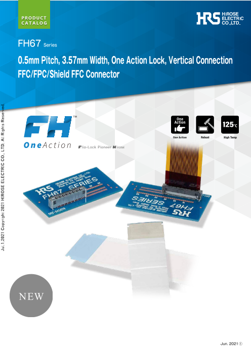
FH67 Series
0.5mm Pitch, 3.57mm Width, One Action Lock, Vertical Connection
FFC/FPC/Shield FFC Connector
Jun. 2021 ①
Jul.1.2021 Copyright 2021 HIROSE ELECTRIC CO., LTD. All Rights Reserved.
Page2
FH67 Series/0.5mm Pitch, 3.57mm Width, One Action Lock, Vertical Connection FFC/FPC/Shield FFC Connector
Features
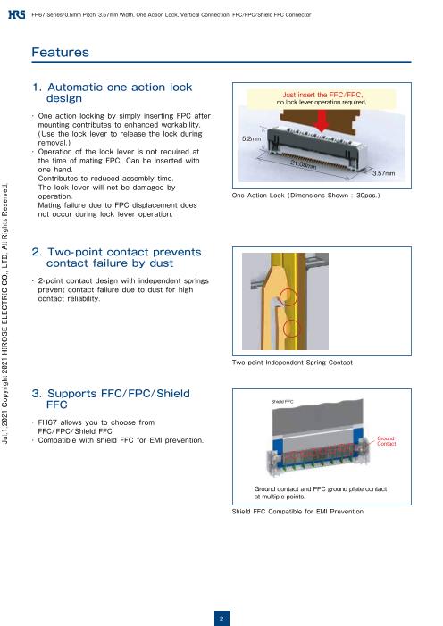
1. Automatic one action lock
design Just insert the FFC/FPC,no lock lever operation required .
・ One action locking by simply inserting FPC after
mounting contributes to enhanced workability.
(Use the lock lever to release the lock during
removal. ) 5.2mm
・ Operation of the lock lever is not required at
the time of mating FPC. Can be inserted with 21.08
one hand. mm 3.57mm
Contributes to reduced assembly time.
The lock lever will not be damaged by
operation. One Action Lock (Dimensions Shown : 30pos. )
Mating failure due to FPC displacement does
not occur during lock lever operation.
2. Two-point contact prevents
contact failure by dust
・ 2-point contact design with independent springs
prevent contact failure due to dust for high
contact reliability.
Two-point Independent Spring Contact
3. Supports FFC/FPC/Shield
FFC Shield FFC
・ FH67 allows you to choose from
FFC/FPC/Shield FFC.
・ Compatible with shield FFC for EMI prevention. GroundContact
Ground contact and FFC ground plate contact
at multiple points.
Shield FFC Compatible for EMI Prevention
2
Jul.1.2021 Copyright 2021 HIROSE ELECTRIC CO., LTD. All Rights Reserved.
Page3
FH67 Series/0.5mm Pitch, 3.57mm Width, One Action Lock, Vertical Connection FFC/FPC/Shield FFC Connector
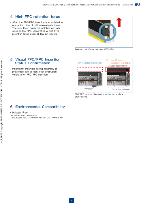
4. High FPC retention force
・ After the FFC/FPC insertion is completed in
one action, the circuit automatically locks.
The lock lever holds the notches on both
sides of the FPC, generating a high FPC
retention force even at low pin counts.
Robust Lock Firmly Secures FFC/FPC
5. Visual FFC/FPC Insertion × : Insufficient
Status Confirmation OK : Mated Condition Insertion Condition
アAクcチtuュatエorー Oタpーenがs半 H開aきlfwにaなyる
・ Insufficient insertion during assembly is
prevented due to lock lever protrusion
visible after FPC/FFC insertion.
Protrusion 突起部 Canno突t 起Seがe見 Pえroなtrいusi on
FFC/FPC can be checked from the top surface
after mating.
6. Environmental Compatibility
・ Halogen Free
*As defined by IEC 61249-2-21.
Br : 900ppm max, Cl : 900ppm max, Br+Cl : 1,500ppm max
3
Jul.1.2021 Copyright 2021 HIROSE ELECTRIC CO., LTD. All Rights Reserved.
Page4
FH67 Series/0.5mm Pitch, 3.57mm Width, One Action Lock, Vertical Connection FFC/FPC/Shield FFC Connector
Product Specifications
Rated Current 0.5A
Rated Voltage 50V AC/DC
Operating Temperature (Note 1) -55 to +125℃
Operating Humidity Range Relative Humidity 90% Max.(No Condensation)
Storage Temperature (Note 2) -10 to +60℃
Storage Humidity Range Relative Humidity 90% Max.(No Condensation)
Adaptive FPC Contact Specifications Thickness : = 0.33 ± 0.03mm Signal Layout : Gold Plated, GND plate : Tin Pated
Note 1 : Includes temperature rise caused by current flow.
Note 2 : The term“ storage” refers to products stored for long period of time prior to mounting and use.
Operating Temperature and Humidity Range covers non-conducting condition of installed connectors in storage, shipment or during transportation.
Item Specification Condition
Insulation Resistance 500MΩ Min. 100V DC
Withstanding Voltage No flashover or insulation breakdown 150V AC for 1 min.
[FPC] First cycle : 60mΩ Max.
After testing : 80mΩ Max.
(Including FPC 8mm conductor resistance)
Contact Resistance Measured at 1mA AC
[FFC] First cycle : 80m Ω Max.
After testing : 100m Ω Max.
(Including FFC 26mm conductor resistance)
Contact resistance : 80mΩ Max. (FPC)
Mating Durability
100mΩ Max. (FFC) 10 cycles
(Insertion/Withdrawal)
No damage, cracks, or parts dislocation
No electrical discontinuity of 1μs or more
Frequency : 10 to 55Hz,
Contact resistance : 80mΩ Max. (FPC)
Vibration single amplitude of 0.75mm,
100mΩ Max. (FFC)
10 cycles in each of the 3 directions
No damage, cracks, or parts dislocation
No electrical discontinuity of 1μs or more Acceleration of 981m/s2,
Contact resistance : 80mΩ Max. (FPC) duration of 6 ms,
Shock
100mΩ Max. (FFC) sine half-wave waveform,
No damage, cracks, or parts dislocation 3 cycles in each of the 3 axes
Contact resistance : 80mΩ Max.(FPC)
100mΩ Max.(FFC) 96 hours at temperature of 60℃ and
Damp Heat (Steady State)
Insulation resistance : 50MΩ Min. humidity of 90% to 95%
No damage, cracks, or parts dislocation
Contact resistance : 80mΩ Max.(FPC) Temperature : -55 → +15 to +35 → +125
100mΩ Max.(FFC) → +15 to +35℃
Temperature Cycle
Insulation resistance : 50MΩ Min. Time : 30 → 2 to 3 → 30 → 2 to 3 (Minutes)
No damage, cracks, or parts dislocation 5 cycles
Resistance to Soldering No deformation of components affecting Reflow : Recommended Temperature Profile
Heat performance Manual Soldering : 350 ± 10℃ for 5 seconds
4
Jul.1.2021 Copyright 2021 HIROSE ELECTRIC CO., LTD. All Rights Reserved.
Page5
FH67 Series/0.5mm Pitch, 3.57mm Width, One Action Lock, Vertical Connection FFC/FPC/Shield FFC Connector
Materials / Finish
Part Materials Finish UL Standard
LCP Grey UL94V-0
Insulator
LCP Black UL94V-0
Signal Contact Copper Alloy Nickel Barrier Gold Plated -
Ground Contact Copper Alloy Pure Tin Reflow Plated -
Reinforcing Retention Tabs Copper Alloy Pure Tin Reflow Plated -
Product Number Structure
Refer to the chart below when determining the product specifications from the product number.
Please select from the product numbers listed in this catalog when placing orders.
FH67 - 30S - 0.5 SV (99)
❶ ❷ ❸ ❹ ❺
❶ Series Name FH67 ❹ Terminal Type SV : SMT Vertical Mounting Type
❷ No. of Pos. 30 ❺ Specification Blank : Standard 1,000pcs/reel
❸ Contact Pitch 0.5mm (99) : 500pcs/reel
5
Jul.1.2021 Copyright 2021 HIROSE ELECTRIC CO., LTD. All Rights Reserved.
Page6
FH67 Series/0.5mm Pitch, 3.57mm Width, One Action Lock, Vertical Connection FFC/FPC/Shield FFC Connector
Connector Dimensions
(A)
B±0.15
Ground Contact No.2
D±0.1 2±0.1 D±0.1
(0.1) Ground Contact No.1
Cavity No.
(C)
E±0.15
2 Polarity Mark 3.57±0.15
1
5 3 HRS Mark Cavity No. Signal Contact No.1 a
(0.15) 4 (0.1) 0.5±0.1
F±0.15
G±0.15
a(10 : 1) (0.955) FPC/FFC/Shield FFC t=0.33 a(10 : 1)
(0.91) (0.42)
(0.25)
Signal
Contact Point
45°)(
Ground
Contact Point
0.25±0.15 0.25±0.15
Lead of Lead of
Reinforcing Reinforcing
Signal Contact Lead Ground Contact Lead Metal Tabs 1.75±0.15 Retention Tabs
0.65±0.1 1.52±0.15 0.65±0.1 1.17±0.1 1.83±0.1 0.57±0.1
(5.45)
Note 1 : The dimensions in parentheses are for reference.
Note 2 : Lead co-planarity including lead of reinforcing metal tabs shall be 0.1mm max.
Note 3 : Delivered in tape and reel packaging.
See the packaging specifications for details.
Note 4 : Note that a preventive hole for sink mark or slit could be added for improvement.
Note 5 : Dark spots may appear on the molded plastic,
however this does not represent a quality issue.
Note 6 : This product satisfies halogen free requirements defined as 900ppm maximum chlorine,
900ppm maximum bromine, and 1500ppm maximum total of chlorine and bromine.
Unit : mm
No. of Purchase Unit
Part No. HRS No. A B C D E F G
Pos. (#):(00) (#):(99)
FH67-10S-0.5SV Under Planning (Note) 10 7.15 4.0 5.0 2.0 11.08 4.5 9.5
FH67-20S-0.5SV Under Planning (Note) 20 12.15 9.0 7.5 1.5 16.08 9.5 14.5
1000pcs per reel 500pcs per reel
FH67-30S-0.5SV CL0580-4901-0-## 30 17.15 14.0 8.0 2.0 21.08 14.5 19.5
FH67-40S-0.5SV CL0580-4903-0-## 40 22.15 19.0 8.0 1.5 26.08 19.5 24.5
Note : Contact positions without HRS No. are currently under planning.
Please contact HRS for detailed information about product variations.
6
Jul.1.2021 Copyright 2021 HIROSE ELECTRIC CO., LTD. All Rights Reserved.
(1.9)
(2.3)
(2.55)
(3.8)
(0.95)
5.2±0.2
Page7
FH67 Series/0.5mm Pitch, 3.57mm Width, One Action Lock, Vertical Connection FFC/FPC/Shield FFC Connector
●Recommended PCB Mounting Pattern
G(±0.02)
2× 0.6±0.02 B (±0.02)
0.02 Z
0.3±0.02 H×
0.02 Z
D 2 D
(0.25)
0.5
0.3±0.02 n×
0.02 Z
F±0.02
2× 0.6±0.02
0.02 Z
G (±0.02)
Z
Note : The value 'n' indicates the number of pos.
●Recommended Stencil Pattern
G (±0.02)
2× 0.6±0.01 B (±0.02)0.02 Y
0.28±0.01 H×0.02 Y
D 2 D
(0.25)
0.5
0.28±0.01 n×
F±0.02 0.02 Y
2× 0.6±0.01
0.02 Y
G (±0.02)
Y
Note : The value 'n' indicates the number of pos.
Unit : mm
No. of
Part No. HRS No. B D E G H
Pos.
FH67-10S-0.5SV Under Planning (Note) 10 4.0 2.0 11.08 9.5 3.0
FH67-20S-0.5SV Under Planning (Note) 20 9.0 1.5 16.08 14.5 6.0
FH67-30S-0.5SV CL0580-4901-0-## 30 14.0 2.0 21.08 19.5 8.0
FH67-40S-0.5SV CL0580-4903-0-## 40 19.0 1.5 26.08 24.5 11.0
Note : Contact positions without HRS No. are currently under planning.
Please contact HRS for detailed information about product variations.
7
Jul.1.2021 Copyright 2021 HIROSE ELECTRIC CO., LTD. All Rights Reserved.
1.13±0.01 1.13±0.03
1.9±0.01 1.25±0.01 1.9±0.02 1.25±0.02
0.22±0.01 0.95±0.01 0.22±0.03 0.82±0.03
1.35±0.01 1.1±0.01 1.25±0.02 1.25±0.02
(0) (0.35)
Page8
FH67 Series/0.5mm Pitch, 3.57mm Width, One Action Lock, Vertical Connection FFC/FPC/Shield FFC Connector
Recommended FFC/FPC/Shield FFC Dimensions
●Recommended FFC/FPC Dimensions
J±0.05
0.8±0.05 (K) 0.8±0.05
F±0.02 X 0.33±0.03
1.3±0.07 1.3±0.07
0.5 n×
R0.2 0.4±0.03 0.02 X
R0.2
R0.2
R0.1±0.1
R0.1±0.1
R0.2
R0.2
1.3±0.07 1.3±0.07
J±0.05
L±0.1
Note : The value 'n' indicates the number of pos.
●Recommended Shield FFC Dimensions
J±0.05
0.8±0.05 (K) 0.8±0.05 0.33±0.3
F±0.05
1.3±0.08 1.3±0.08 W
R0.2 0.5 0.32±0.03 n× 1.1±0.3 (M) 1.1±0.3
R0.2 0.05 W
R0.2
R0.1±0.1
R0.1±0.1
R0.2
R0.2
1.3±0.08 1.3±0.08
Ground Plate
J±0.05 Shield Tape
L±0.1
Note 1 : The value 'n' indicates the number of pos.
Note 2 : Place the shield tape on top of the grounding plate.
Unit : mm
No. of
Part No. HRS No. F J K L M
Pos.
FH67-10S-0.5SV Under Planning (Note) 10 4.5 7.1 5.5 9.1 4.9
FH67-20S-0.5SV Under Planning (Note) 20 9.5 12.1 10.5 14.1 9.9
FH67-30S-0.5SV CL0580-4901-0-## 30 14.5 17.1 15.5 19.1 14.9
FH67-40S-0.5SV CL0580-4903-0-## 40 19.5 22.1 20.5 24.1 19.9
Note : Contact positions without HRS No. are currently under planning.
Please contact HRS for detailed information about product variations
8
Jul.1.2021 Copyright 2021 HIROSE ELECTRIC CO., LTD. All Rights Reserved.
1.25±0.1
2.9±0.1
4.15±0.1
4.75±0.3
1MIN(Overlapping Amount)
6MIN(Reinforcing Film) 1.25±0.1
2.9±0.1
4.15±0.1
0.5±0.3 4.75±0.3
1MIN(OverlApping Amount)
6MIN(Reinforcing Film)
Page9
FH67 Series/0.5mm Pitch, 3.57mm Width, One Action Lock, Vertical Connection FFC/FPC/Shield FFC Connector
Recommended FFC/FPC/Shield FPC Composition
②Cover Lay Film ①Shield Tape ④Surface Treatment
③Cover Lay Adhesive
⑥Base Adhesive
⑤Pattern Copper Foil
⑦Base Material
⑧Reinforcing Film Adhesive
⑨Reinforcing Film
⑩Ground Plate Adhesive
⑬Shield Tape
⑪Ground Plate
⑫Surface Treatment
FPC FFC
Material Name Thickness Shield FFC FFCMaterials (µm) Materials Thickness(µm)
① Shield Tape ―― ―― ――
② Cover Lay Film Polyimide 1mil 25 Polyester 25 25
③ Cover Lay Adhesive Thermosetting Adhesive 28 Adhesive 25 25
④ Surface Treatment Nickel Underplated 1 to 6µm (3.7) Nickel Underplated 0.5 to 5µm+Gold Plated 0.2µm +Gold Plated 0.05 to 1µm (3.275) (3.275)
⑤ Pattern Copper Foil Rolled Copper 1oz 35 Annealed Copper foil 35 35
⑥ Base Adhesive Thermosetting Adhesive 8 Adhesive 25 25
⑦ Base Material Polyimide 1mil 25 Polyester 25 50
⑧ Reinforcing Film Adhesive Thermosetting Adhesive 55 Adhesive 30 30
⑨ Reinforcing Film Polyimide 8mil 200 Polyester 150 188
⑩ Ground Plate Adhesive ―― ―― Adhesive 30 ――
⑪ Ground Plate ―― ―― Copper foil
⑫ Surface Treatment ―― ―― Tin plated 1 to 5µm
37 ――
⑬ Shield Tape ―― ―― ――
Note 1 : This specification is recommendation for the construction of the FH67 Series
FFC/FPC/Shield FFC (t=0.33± 0.03mm)
Note 2 : For details about the construction, please contact FFC/FPC/Shield FFC manufacturers.
9
Jul.1.2021 Copyright 2021 HIROSE ELECTRIC CO., LTD. All Rights Reserved.
Page10
FH67 Series/0.5mm Pitch, 3.57mm Width, One Action Lock, Vertical Connection FFC/FPC/Shield FFC Connector
Packaging Specifications
●Embossed Carrier Tape Dimensions
Tape Width : 24mm or less Tape Width : 32mm or less
8±0.1
(5.4) φ 4±0.1
(0.4) 1.5 + (2)
8±0.1 00 .1
(5.4) φ 4±0.11.
(0.4) 5 +0 (2)0 .1
7
7
6 6
9
9
(0.95()Automotive Mounting Suction Surface)
(C()Automotive Mounting Suction Surface)
Unreeling Direction
(0.95()Automotive Mounting Suction Surface)
(C()Automotive Mounting Suction Surface)
Unreeling Direction
●Reel Dimensions ●Leader, Trailer Dimensions
S±1(Reel Outer Width) Unreeling Direction
8
Unreeling Direction 400mm Min. (Leader)
160mm Min. 100mm Min.
(Trailer, Empty (Empty Components)
Components)
Embossed Carrier Tape
Top Cover Tape
U±1(Reel Inner Width)
Note : 1000pcs per reel (standard product).
The package complies with JIS C 0806 and IEC 60286-3
(Packaging of components for automatic handling).
Unit : mm
No. of
Part No. HRS No. C P Q R S U
Pos.
FH67-10S-0.5SV Under Planning (Note) 10 5 24 - 11.5 29.4 25.4
FH67-20S-0.5SV Under Planning (Note) 20 7.5 32 28.4 14.2 37.4 33.4
FH67-30S-0.5SV CL0580-4901-0-## 30 8 44 40.4 20.2 49.4 45.4
FH67-40S-0.5SV CL0580-4903-0-## 40 8 44 40.4 20.2 49.4 45.4
Note : Contact positions without HRS No. are currently under planning.
Please contact HRS for detailed information about product variations.
10
Jul.1.2021 Copyright 2021 HIROSE ELECTRIC CO., LTD. All Rights Reserved.
(φ13)
φ380±2
φ80±1
R±0.1 1.75±0.1
P±0.3
R±0.1 1.75±0.1
Q±0.1
P±0.3
Page11
FH67 Series/0.5mm Pitch, 3.57mm Width, One Action Lock, Vertical Connection FFC/FPC/Shield FFC Connector
Temperature Profile
MAX 250℃
245
Applicable Conditions
220℃
Reflow method : IR/Hot air
200 Reflow environment : Room air
180℃
Solder : Paste type Sn/3.0Ag/0.5Cu
(M705-GRN360-K2-V made by Senju Metal Industry Co.)
150
150℃ Test PCB : PCB material and size
Glass epoxy 45×25×1mm
As Listed in Recommended PCB Mounting Pattern
100
Metal mask : Thickness and opening size
20 to 40
sec. As Listed in Recommended Metal Mask Dimensions
50 (Peak temperature)
This temperature profile is based on the above conditions.
25℃ 120±5 sec. 60 to 90 sec. It may vastly depending on solder paste type,
(Preheating time) (Soldering time)
0 manufacturer, PCB size and mounting materials. Please
Start use only after checking the mounting conditions.
Time (Sec. )
11
Jul.1.2021 Copyright 2021 HIROSE ELECTRIC CO., LTD. All Rights Reserved.
Temperature (℃)
Page12
FH67 Series/0.5mm Pitch, 3.57mm Width, One Action Lock, Vertical Connection FFC/FPC/Shield FFC Connector
Connector Operation and Precautions
●Operation Method
Handle this connector with care.To prevent damage to the connector and contact failure
( incomplete mating, FPC pattern disconnection) , confirm the following before use.
This connector supports FFC/FPC/Shield FFC, however, for convenience, only FPC is listed.
Top Surface
(Suction Surface)
(FPC Insertion Port)
Lock Lever
Insulation Case ReinforcingRetention Tabs Bottom Surface
(Mounting Surface)
Signal Contact
Ground Contact
1. Initial Delivery State
This product is delivered with the lock lever closed. The lock lever does not need to be operated before
FPC insertion.
[Caution]
・ Do not open the lock lever when FPC is not inserted.
Additionally, the lock lever does not need to be opened except to remove the FPC. (Ex.1)
・ Do not operate the connector until it is mounted on the board. (Ex.1)
(Ex.1)
Delivered State FPC not Inserted
Lock Lever (Closed)
Unmounted Lock Lever (Cpen)
12
Jul.1.2021 Copyright 2021 HIROSE ELECTRIC CO., LTD. All Rights Reserved.
Page13
FH67 Series/0.5mm Pitch, 3.57mm Width, One Action Lock, Vertical Connection FFC/FPC/Shield FFC Connector
2. FPC Insertion
Insert the FPC fully perpendicular in respect to the board surface (Ex.2) .
[Caution]
· Please confirm that the lock lever is closed during FPC insertion.
Do not insert FPC while the lock lever is open. (Ex.3)
Product is designed so that the FPC cannot be inserted when the lock lever is opened. However forcing
insertion causes damage.
· Do not insert FPC while at the same time pressing the lock lever. (Ex.4)
· Insert FPC pattern side facing opposite of the operating portion of the lock lever. (Ex.5)
· Insert FPC straight after positioning its tip vertically in reference to the guides on both ends of the
connector mating port. (Ex.6)
· Do not insert at an angle to the insertion direction. (Ex.7)
· When inserting, do not move the FPC in a vertical, lateral or diagonal direction. (Ex.8)
(Recommended Insertion Angle ±2.5°)
· Refrain from opening the lock level with a finger when inserting the FPC. (Ex.9)
(Ex.2) (Ex.3) (Ex.4)
FPC (Vertical)
Lock Lever (Closed) Lock Lever (Open)
(Ex.5) (Ex.6)
FPC Pattern Side
FPC (Vertical)
Operating Portion
of Lock Lever
Lock Lever (Closed)
Insert FPC straight after positioning both its
ends vertically in reference to the guides on
both ends of the connector mating port.
13
Jul.1.2021 Copyright 2021 HIROSE ELECTRIC CO., LTD. All Rights Reserved.
Page14
FH67 Series/0.5mm Pitch, 3.57mm Width, One Action Lock, Vertical Connection FFC/FPC/Shield FFC Connector
(Ex.7) (Ex.8) (Ex.9)
FPC (Diagonal)
±2.5
FPC
(Angled)
Lock Lever (Open)
3. FPC Mated State Confirmation
When FPC is completely inserted, visually inspect the inserted status of FPC. (Ex.10)
(This connector uses the lock protrusion of the lock lever for FPC positioning. )
[Caution]
· Avoid shallow FPC insertion or insertion at a slant. (Ex.11) (Ex.12)
· The lock lever does not need to be operated after FPC insertion due to the one action lock design.
(Ex.10) (Ex.11) (Ex.12)
FPC is not inserted deep enough, FPC is inserted at an angle.
leaving a large gap between leaving a large gap between
FPC and the housing. FPC and the housing.
FPC inserted to the back of the FPC is not inserted fully enough to FPC is inserted diagonally,
mating port. reach the back of the mating port. and is not inserted fully enough to
reach the back of the mating port.
Can see viewing port when Cannot see viewing Cannot see viewing
FPC is inserted to the back of port when FPC is port when FPC is
the mating port. not fully inserted. not fully inserted.
The lock lever protrusion The lock lever protrusion
covers the FPC tab. covers the FPC tab.
Locking Portion Cross-section Locking Portion Cross-section Locking Portion Cross-section
14
Jul.1.2021 Copyright 2021 HIROSE ELECTRIC CO., LTD. All Rights Reserved.
MA
X
°
Page15
FH67 Series/0.5mm Pitch, 3.57mm Width, One Action Lock, Vertical Connection FFC/FPC/Shield FFC Connector
4. How to Unlock the Lock Lever
Push down the lock lever slowly, and release the lock. (Ex.13)
[Caution]
· When releasing the lock operate the lock lever around the center. (Ex.14)
· When releasing the lock do not operate only one side of the lock lever. (Ex.15)
· As the lock lever cannot be opened to over 45°, do not open it over this angle. (Ex.16)
· Do not pick and raise the lock lever or pull it. (Ex.17)
· Be sure to operate the lock lever by hand, and do not operate it with sharp-edged tools such as tweezers etc. (Ex.18)
· Don' t apply an excessive force to the housing during operation. (Ex.19)
(Ex.13)
(Ex.14) (Ex.15)
Operate the lock lever around the center. Operate the lock lever on one side.
15
Jul.1.2021 Copyright 2021 HIROSE ELECTRIC CO., LTD. All Rights Reserved.
Page16
FH67 Series/0.5mm Pitch, 3.57mm Width, One Action Lock, Vertical Connection FFC/FPC/Shield FFC Connector
(Ex.16) (Ex.17)
Rotation Axis
Opening the lock lever Load is concentrated on the rotation
at more than 45°. axis and leads to breakage.
(Ex.18) (Ex.19)
Sharp-edged Tools
Applying excessive force to the lock lever.
16
Jul.1.2021 Copyright 2021 HIROSE ELECTRIC CO., LTD. All Rights Reserved.
45°
Page17
FH67 Series/0.5mm Pitch, 3.57mm Width, One Action Lock, Vertical Connection FFC/FPC/Shield FFC Connector
5. FPC Removal Method
After releasing the lock lever, remove the FPC perpendicular to the board surface. (Ex.20)
When removing the FPC do not press the lock lever. (Ex.21)
The released lock lever is designed to close automatically at the time of FPC release.
However if it does not please close the lock with your finger. (Ex.22)
[Caution]
· Do not pull out FPC while the lever is locked. (Ex.23)
There is a possibility of decrease in the FPC's retention force after forcefully removing the FPC.
· The lock lever provides the FPC retention mechanism.
When pulling out FPC, do not apply load in any direction other than perpendicular to the board surface. (Ex.24)
(Ex.20) (Ex.21)
Vertical
Direction
Lock Lever (Open)
Lock Lever (Open)
(Ex.22) (Ex.23)
― After FPC Removal ―
Automatically returns to
position at the same time
as FPC removal.
Lock Lever (Closed)
Lock Lever (Closed)
(Ex.24)
FPC (Angled)
FPC (Angled)
17
Jul.1.2021 Copyright 2021 HIROSE ELECTRIC CO., LTD. All Rights Reserved.
Page18
FH67 Series/0.5mm Pitch, 3.57mm Width, One Action Lock, Vertical Connection FFC/FPC/Shield FFC Connector
●PCB Layout Precautions
Stress leading to contact failure may be applied to the connector depending on the routing of the FPC the connector will
be mated with.
In order to prevent failure, please consider the following during mechanical design.
[Caution]
· When routing the FPC for use, make sure it has enough slack and do not pull tightly.
Please check that the reinforcing film is placed vertical to the board surface. (Ex.25)
· Please ensure there is no load applied to the connector in the pulling, inserting or lateral direction.
Using an FPC bent close to the connector may cause contact failure or FPC damage/disconnection.
Therefore, please take some measure to secure the FPC etc. (Ex.26) (Ex.27)
· Do not place panels or mounted parts that interfere with the FPC. (Ex.28)
· Please make adjustments with FPC manufacturer for FPC flexibility.
· Please ensure the FPC has adequate insertion space when designing the layout so that it is not inserted diagonally.
Additionally, insertion becomes difficult if the FPC is too short, so please ensure an adequate FPC length and component
layout.
· When you design the board/ layout, please secure required space for operation.
(Ex.25) (Ex.26)
Routing that Does Not Place a Load
on the Reinforcing Film Routing that Places a Load
on the Reinforcing Film
Reinforcing Film Reinforcing Film
(Ex.27) (Ex.28)
Load Applied to FPC Housing/Mounted Components
Interfering with FPC
18
Jul.1.2021 Copyright 2021 HIROSE ELECTRIC CO., LTD. All Rights Reserved.
Page19
FH67 Series/0.5mm Pitch, 3.57mm Width, One Action Lock, Vertical Connection FFC/FPC/Shield FFC Connector
Notes for Board Mounting and After Board Mounting
●Board Mounting Notes
Please be careful of the following at the time of board mounting.
[Caution]
· Please confirm the recommended PCB mounting pattern, metal mask opening size and FPC design.
· If the PCB mounting pattern is narrower than recommended or the metal mask opening is wider than recommended,
solder (flux) wicking is more likely to occur.
If there is difference from the recommendation, please use after checking the mounting state.
· The level difference between the bottom surfaces of contact lead and the mold is designed to be minimal. When there is
silk print etc. on the bottom surface of the connector, the lower surface of the connector may be pushed up, resulting
in solder not applied or defective fillet formation. When there is silk print etc. on the bottom surface of the connector,
please use after checking the mounted state.
· Use the reflow conditions within the specifications designated by Hirose. The mounted status may vary due to external
conditions such as the paste solder type, manufacturer, and board size. Please use it after checking the mounted state.
· Please control the board warpage as much as possible. While the coplanarity of this connector is 0.1mm or less,
defective soldering could occur if the board warpage is considerable.
· When mounted on FPC, be sure to provide a reinforcing plate to ease handling. We recommend a reinforcing plate of
0.3mm or thicker made of glass epoxy material.
· Do not apply excessive force (1N or more) when pulling out the emboss from the reel or suctioning the connector from
the emboss.
●Cautions When Handling the Board After Mounting
Please be careful of the following when handling the board after mounting operation.
[Caution]
· Refrain from handing that may put strain on the board during the assembly process, such as splitting a board into
several pieces or screwing the board to a frame. Otherwise the connector may be damaged.
· Board deflection should be 1mm or less when the board width is 100mm. (Ex.29) Board deflection may cause stress to
the connector resulting in damage.
(Ex.29)
100
Connector
Connector
PCB
100
●Cautions for Manual Soldering
Please be careful of the following when hand-soldering for repair work etc.
[Caution]
· Do not perform manual soldering with the FPC inserted in the connector.
· Please be careful not to apply excessive heat or allow the solder iron to touch any place other than the
connector contact lead. Failure to do so may result in connector deformation or melting.
· Do not supply an excessive amount of solder (flux) . If too much solder (flux) is supplied to the contact, the solder
or flux could adhere on the contact point and cause contact failure. Additionally, supplying excessive solder to the
retention tabs may result in actuator rotation failure, causing connector damage.
19
Jul.1.2021 Copyright 2021 HIROSE ELECTRIC CO., LTD. All Rights Reserved.
1 MAX 1 MAX
Page20
FH67 Series/0.5mm Pitch, 3.57mm Width, One Action Lock, Vertical Connection FFC/FPC/Shield FFC Connector
While Taking into Consideration
Specifications mentioned in this catalog are reference values.
When considering to order or use this product, please confirm the Drawing and Product Specifications sheets.
Use an appropriate cable when using the connector in combination with cables.
If considering usage of a non-specified cable, please contact your sales representative.
If assembly process is done by jigs & tools which are not identified by Hirose, assurance will not be given.
If considering usage for below mentioned applications, please contact your sales representative.
In cases where the application will demand a high level of reliability, such as automotive, medical instruments, public
infrastructure, aerospace/ defense etc. Hirose must review before assurance of reliability can be given.
2-6-3,Nakagawa Chuoh,Tsuzuki-Ku,Yokohama-Shi 224-8540,JAPANhttps://www.hirose.com
※The contents of this catalog are current as of date of 6/2021. Contents are subject to change without notice for the purpose of improvements.
20
Jul.1.2021 Copyright 2021 HIROSE ELECTRIC CO., LTD. All Rights Reserved.