


Ultra-small, power/signal contact design for Board-to-Board/FPC-to-Board providing 3A max current
Features
Ultra-small, power/signal contact design for Board-to-Board/FPC-to-Board providing 3A max current
1. The world smallest size* contributes to size reduction and flexible design of mobile devices.
- Pitch: 0.35mm, Depth: 1.5mm, tacking Height: 0.6mm
2. Power contacts combination enables 3A power delivery. Power + signal hybrid type
- Rated current: 3A for power, 0.3A for signal
3. Unique metal guides prevent the housing damage due to offset mating. (Self-alignment with guide ribs)
4. Secure mating with clear tactile click
5. High contact reliability with 2-point contact design
*:As of January, 2020
Document Information
| Document Title | Hirose Electric BM29 Series |
|---|---|
| Document Type | Product Catalog |
| File size | 379.2Kb |
| Company | IIDA ELECTRONICS (Documents List) |
Documents related to this company


Document Contents
Page1
Ultra-small, power/signal contact design for Board-to-Board/FPC-to-Board providing 3A max current
BM29 Series
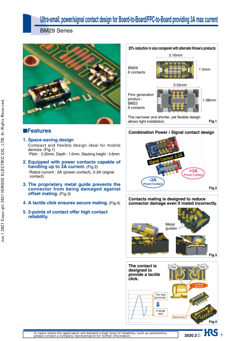
20% reduction in size compared with alternate Hirose’s products
3.16mm
BM29 1.5mm
6 contacts
3.55mm
Prior generation
product : 1.98mm
BM23
6 contacts
The narrower and shorter, yet flexible design
allows tight installation. Fig.1
■Features Combination Power / Signal contact design
1. Space-saving design
Compact and flexible design ideal for mobile
devices. (Fig.1)
・Pitch : 0.35mm, Depth : 1.5mm, Stacking height : 0.6mm
2. E quipped with power contacts capable of
handling up to 3A current. (Fig.2)
・ Rated current : 3A (power contact), 0.3A (signal
contact)
3. T he proprietary metal guide prevents the
connector from being damaged against Fig.2
offset mating. (Fig.3)
Contacts mating is designed to reduce
4. A tactile click ensures secure mating. (Fig.4) connector damage even if mated incorrectly.
5. 2 -points of contact offer high contact
reliability.
Metal
guides
Fig.3
The contact is Click! Click!
designed to
provide a tactile
click.
Locking
groove
The load
plummets.
A tactile
click
Metal locks
Fig.4
In cases where the application will demand a high level of reliability, such as automotive,
please contact a company representative for further information. 2020.2② 1
Jun.1.2021 Copyright 2021 HIROSE ELECTRIC CO., LTD. All Rights Reserved.
Page2
BM29 Series●Ultra-small, power/signal contact design for Board-to-Board/FPC-to-Board providing 3A max current
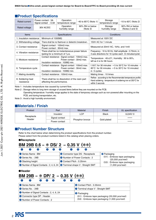
■Product Specifi cations
Power contact : 3A Operation Storage
Rated current -40 to 85°C (Note 1) -10 to 60ç (Note 2)
Signal contact : 0.3A temperature range temperature range
Operation 90% RH or below Storage 90% RH or below
Rated voltage 30V AC/DC
humidity range (Note 3) humidity range (Notes 2 and 3)
Items Specifi cations Conditions
1. Insulation resistance Minimum of 1000Mø Measured at 100V DC
2. Withstanding voltage There shall be no fl ashover or dielectric breakdown. 150V AC for 1 minute
Signal contact : 100mø max.
3. Contact resistance Measured at 20mV AC, 1kHz, and 1mA
Power contact : 30mø max.
There shall be no instantaneous power failure Frequency : 10 to 55 Hz, Half amplitude : 0.75mm, in
4. Vibration resistance
lasting for a minimum of 1µs. 3 axis directions for 10 cycles each (5 minutes/cycle)
Contact resistance : Signal contact : 100mø max.
Temperature : 40±2ç, Humidity : 90 to 95%,
5. Moisture resistance Power contact : 30mø max.
left as it is for 96 hours
Insulation resistance : 100Mø min.
Contact resistance : Signal contact : 100mø max. (-55ç for 30 minutes ➝ 5 to 35°C for 10 minutes ➝
6. Temperature cycle Power contact : 30mø max. 85°C for 30 minutes ➝ 5 to 35°C for 10 minutes)
Insulation resistance : 100Mø min. in 5 cycles
7. Mating durability Contact resistance : 100mø max. Mating times : 10 times
Refl ow : according to the Recommended temperature profi le
8. Soldering heat There shall be no dissolution of the resin part
Hand soldering : temperature of soldering iron at 350°C for
resistance affecting the performance.
within 3 seconds
Note 1 : Includes temperature rise caused by current fl ow.
Note 2 : S torage refers to long-term-storage of unused items before they are mounted on the PCB.
Operating temperature / humidity range applies to the state of temporary storage such as non-powered after mounting on the
PCB, and during transportation, etc.
Note 3 : A void a high humidity environment.
■Materials / Finish
Product Part Material Finish UL specifi cation
Insulator LCP Black UL94V-0
Receptacle
Signal contact ----------
Header Phosphor bronze Gold plated
Power contact ----------
■Product Number Structure
Refer to the chart below when determining the product specifications from the product number.
Please select from the product numbers listed in this catalog when placing orders.
●Receptacle
BM 29B 0.6 − * DS/ 2 − 0.35 V (**)
❹ ❺ ❻ ❼ ❽
Series Name : BM Connector type DS : Receptacle Packaging
Series No. : 29B Number of Power Contacts : 2 (51) : Emboss tape packaging
(20,000 pcs/reel)
Stacking height Contact Pitch : 0.35mm (53) : Emboss tape packaging
Number of Signal Contacts : 2, 4, 6, 24 Terminal shape V : Straight SMT (1,000 pcs/reel)
●Header
BM 29B − * DP/ 2 − 0.35 V (**)
❹ ❺ ❻ ❼ ❽
Series Name : BM Contact Pitch : 0.35mm
Series No. : 29B Terminal shape V : Straight SMT
Number of Signal Contacts : 2, 4, 6, 24 Packaging
Connector type DP : Header (51) : Emboss tape packaging (20,000 pcs/reel)
Number of Power Contacts : 2 (53) : Emboss tape packaging (1,000 pcs/reel)
2
Jun.1.2021 Copyright 2021 HIROSE ELECTRIC CO., LTD. All Rights Reserved.
Page3
BM29 Series●Ultra-small, power/signal contact design for Board-to-Board/FPC-to-Board providing 3A max current
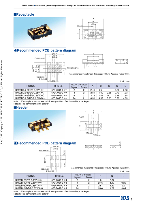
■Receptacle
A
B
C
P=0.35
□Recommended PCB pattern diagram
D±0.02 D
E±0.02 E
C±0.02
P=0.35±0.02
Insulation area
Recommended metal mask thickness : 100µm, Aperture ratio : 100%
0.3±0.02
0.46±0.02
0.18±0.02 Unit:mm
No. of Contacts
Part No. HRS No. A B C D E
Signal Power
BM29B0.6-2DS/2-0.35V(**) 673-7001-0 ** 2 2 2.46 0.7 - 2.08 0.98
BM29B0.6-4DS/2-0.35V(**) 673-7063-0 ** 4 2 2.81 1.09 0.35 2.43 1.33
BM29B0.6-6DS/2-0.35V(**) 673-7003-0 ** 6 2 3.16 1.44 0.7 2.78 1.68
BM29B0.6-24DS/2-0.35V(**) 673-7053-0 ** 24 2 6.31 4.59 3.85 5.93 4.83
Note 1 : Please place your orders for full reel quantities of embossed tape packages.
Note 2 : This connector has no polarity.
■Header
F
G
H
P=0.35
0.12
0.19
□Recommended PCB pattern diagram
G±0.02
H±0.02
P=0.35±0.02
Recommended metal mask thickness : 100µm, Aperture ratio : 80%
0.25±0.02
0.18±0.02 Unit:mm
No. of Contacts
Part No. HRS No. F G H
Signal Power
BM29B-2DP/2-0.35V(**) 673-7002-0 ** 2 2 1.81 0.77 -
BM29B-4DP/2-0.35V(**) 673-7064-0 ** 4 2 2.16 1.12 0.35
BM29B-6DP/2-0.35V(**) 673-7004-0 ** 6 2 2.51 1.47 0.7
BM29B-24DP/2-0.35V(**) 673-7052-0 ** 24 2 5.66 4.62 3.85
Note 1 : Please place your orders for full reel quantities of embossed tape packages.
Note 2 : This connector has no polarity.
3
Jun.1.2021 Copyright 2021 HIROSE ELECTRIC CO., LTD. All Rights Reserved.
1.82+0.05 0
1.180-0.05
0.980-0.05
1.61+0.05 0
0.55 (0.53)
1.5
1.4
0.41
0.6
Page4
BM29 Series●Ultra-small, power/signal contact design for Board-to-Board/FPC-to-Board providing 3A max current
□Embossed Tape Dimensions (conforms to JIS C 0806)
●Receptacle ●Reel dimensions
4±0.1 2±0.1 4±0.1 Product label
2±0.5
K K-K
Ø1.5 feed hole
diameter
N±0.5
Q±1
K
0.2±0.1
J J
J-J 0.74±0.15
Unit:mm
Part No. HRS No. No. of ContactsSignal Power L M N Q
BM29B0.6-2DS/2-0.35V(**) 673-7001-0 ** 2 2 5.5 12 13.5 17.5
BM29B0.6-4DS/2-0.35V(**) 673-7063-0 ** 4 2 5.5 12 13.5 17.5
BM29B0.6-6DS/2-0.35V(**) 673-7003-0 ** 6 2 5.5 12 13.5 17.5
BM29B0.6-24DS/2-0.35V(**) 673-7053-0 ** 24 2 7.5 16 17.4 21.4
●Header ●Reel dimensions
4±0.1 2±0.1 4±0.1 Product label
2±0.5
M M-M
Ø1.5 feed hole
diameter
W±0.5
X±1
M 0.2±0.1
L L 0.55±0.15L-L
Unit:mm
Part No. HRS No. No. of ContactsSignal Power T U W X
BM29B-2DP/2-0.35V(**) 673-7002-0 ** 2 2 5.5 12 13.5 17.5
BM29B-4DP/2-0.35V(**) 673-7064-0 ** 4 2 5.5 12 13.5 17.5
BM29B-6DP/2-0.35V(**) 673-7004-0 ** 6 2 5.5 12 13.5 17.5
BM29B-24DP/2-0.35V(**) 673-7052-0 ** 24 2 7.5 16 17.4 21.4
4
Jun.1.2021 Copyright 2021 HIROSE ELECTRIC CO., LTD. All Rights Reserved.
Ø1.5+0.10
T±0.1 1.75±0.1
U±0.3 L±0.1 1.75±0.1
M±0.3
12 10 2° 0°
Ø13 ر 130 ±.2 0.2
Ø380±2 Ø380±2
Ø80±1 Ø80±1
120
°
120
°
0.8 .8± ±0
Ø21 Ø21
+0.1
Ø1.5 0
Page5
BM29 Series●Ultra-small, power/signal contact design for Board-to-Board/FPC-to-Board providing 3A max current
Precautions
1. Recommended MAX 250℃
temperature profi le
250
220 220℃
200 180℃
180
150 150℃
100
50
25℃
25 (60 seconds) 90 to 120 seconds (60 seconds)
0 Preheating time Soldering time
Start
Time (seconds)
[Conditions]
1. Peak temperature : 250ç
2. Heating unit : No less than 220ç for no more than 60 seconds
3. Preheating unit : 150 to 180ç for 90 to 120 seconds
4. Number of times : No more than 2 times
Note 1 : The temperature is the surface temperature of the PCB in the vicinity of the connector
lead part.
Note 2 : W hen you use nitrogen refl ow, please mount the product with the oxygen concentration
at a minimum of 1,000 [ppm].
Please contact us if the concentration is below 1,000 [ppm].
2. Recommended hand Soldering iron temperature : 340 ± 10°C,
soldering conditions Soldering time : within 3 seconds
3. Recommended screen
Thickness : 0.1mm
thickness/aperture ratio
Aperture ratio : 100% on the DS side ; 80% on the DP side
(pattern area ratio)
4. Warpage of the PCB A maximum of 0.02mm at the center part of the connector based on both ends of the connector.
5. Cleaning Not recommended. If you clean this product, please evaluate the performance before using it.
(Cleaning may cause a change in the mating/unmating property and its resistance to
environment)
6. Notes ■Care should be taken that mating/unmating operation when the product is not mounted on the
PCB could cause damage or deformation, etc. of the contact.
■Avoid supporting the PCB only by connectors, and support it by other means than connectors.
■Care should be taken that excessive prying mating/unmating could cause damage.
■D uring hand soldering, do not apply fl ux which will cause fl ux oozing on connector.
■ This product may differ in hue due to production lot variability, but it doesn’t have any
infl uence on the performance.
■Please refer to the next page for the precautions for mating/unmating.
■C onsidering the possibility of disengagement due to the counterforce caused by the drop, impact
and routing of FPC, fi x the mated state by the use of housings and cushion materials, etc.
■ Caution! Do not use the connector in non-recommended conditions (i.e., rated current, rated
voltage, PCB design and operating environment, etc.). Such usage could lead to material
outgassing, ignition, or short-circuit, etc.
Refer to the specifi cations and the guidelines for board pattern dimensions, board cautions,
and connector treatment.
Pleasae contact Hirose if using the connector under conditions other than those described in
the specifi cations and the guidelines is being considered.
5
Jun.1.2021 Copyright 2021 HIROSE ELECTRIC CO., LTD. All Rights Reserved.
Temperature(℃)
Page6
BM29 Series●Ultra-small, power/signal contact design for Board-to-Board/FPC-to-Board providing 3A max current
●Notes when mating connector
Be sure to mate this product manually.
Mating procedure
1)Align the connector at the guide.
A guide rib (tapered metal) is provided on the outer wall of the connector for mating support.
Align the connector to this guide rib.
2)The connector enters automatically.
The connector slightly lowers when aligned correctly.
Find the guide by moving the connector in the X and Y directions.
Finding
Finding The connector slightly lowers when aligned.
3)Once aligned, mate the connector fully.
The connector becomes parallel when aligned. You cannot move it laterally and longitudinally.
4)Confirm the mated connector.
If incorrectly mated, remove, and mate it again.
6
Jun.1.2021 Copyright 2021 HIROSE ELECTRIC CO., LTD. All Rights Reserved.
Page7
BM29 Series●Ultra-small, power/signal contact design for Board-to-Board/FPC-to-Board providing 3A max current
●Notes when unmating connector
1)Vertical direction
When removing the connector, remove it vertically. Number of contacts, FPC thickness, or other factors may make the
vertical removal difficult.
OK OK
2)Longitudinal removal
Remove the connector in the pitch direction in a slanted manner.
OK
3)Lateral removal
Pull out the tip end of the FPC in the vertical direction.
Applying a large force horizontally could deform the contacts.
OK NG
4)Evaluate the mated state for thin FPCs.
C onnector breakage or peeling off at soldering area could occur if the FPC does not have enough rigidity,
please check the action in advance on the same type of FPC.
Thin FPC
7
Jun.1.2021 Copyright 2021 HIROSE ELECTRIC CO., LTD. All Rights Reserved.
Page8
BM29 Series●Ultra-small, power/signal contact design for Board-to-Board/FPC-to-Board providing 3A max current
USA: USA: USA:
HIROSE ELECTRIC (U.S.A.), INC. HEADQUARTERS CHICAGO OFFICE HIROSE ELECTRIC (U.S.A.), INC. SAN JOSE OFFICE HIROSE ELECTRIC (U.S.A.), INC. DETROIT OFFICE (AUTOMOTIVE)
2300 Warrenville Road, Suite 150, 2841 Junction Ave, Suite 200 17197 N. Laurel Park Drive, Suite 253,
Downers Grove, IL 60515 San Jose, CA. 95134 Livonia, MI 48152
Phone : +1-630-282-6700 Phone : +1-408-253-9640 Phone : +1-734-542-9963
http://www.hirose.com/us/ Fax : +1-408-253-9641 Fax : +1-734-542-9964
http://www.hirose.com/us/ http://www.hirose.com/us/
USA: THE NETHERLANDS: GERMANY:
HIROSE ELECTRIC (U.S.A.), INC. BOSTON OFFICE HIROSE ELECTRIC EUROPE B.V. HIROSE ELECTRIC EUROPE B.V. GERMAN BRANCH
300 Brickstone Square Suite 201, Hogehillweg #8 1101 CC Amsterdam Z-O Schoenbergstr. 20, 73760 ostfildern
Andover, MA 01810 Phone : +31-20-6557460 Phone : +49-711-456002-1
Phone : +1-978-662-5255 Fax : +31-20-6557469 Fax : +49-711-456002-299
http://www.hirose.com/eu/ http://www.hirose.com/eu/
GERMANY: GERMANY: FRANCE:
HIROSE ELECTRIC EUROPE B.V. NUREMBERG OFFICE HIROSE ELECTRIC EUROPE B.V. HANOVER OFFICE HIROSE ELECTRIC EUROPE B.V. PARIS OFFICE
Neumeyerstrasse 22-26, 90411 Nurnberg Bayernstr. 3, Haus C 30855 Langenhagen, Germany 130 Avenue Joseph Kessel, Bat E, 78960
Phone : +49-911 32 68 89 63 Phone : +49-511 97 82 61 30 Voisins le Bretonneux, France
Fax : +49-911 32 68 89 69 Fax : +49-511 97 82 61 35 Phone : +33-1-85764886
http://www.hirose.com/eu/ http://www.hirose.com/eu/ Fax : +33-1-85764823
http://www.hirose.com/eu/
UNITED KINGDOM: CHINA: CHINA:
HIROSE ELECTRIC EUROPE BV (UK BRANCH) HIROSE ELECTRIC (CHINA) CO., LTD. (SHANGHAI, HEADQUARTERS) HIROSE ELECTRIC (CHINA) CO.,LTD. BEIJING BRANCH
4 Newton Court, Kelvin Drive, Knowlhill, 18, Enterprise Center Tower 2, 209# Gong He A1001, Ocean International Center, Building 56# East 4th
Milton Keynes, MK5 8NH Road, Jing’an District, Shanghai, CHINA 200070 Ring Middle Road, ChaoYang District, Beijing, 100025
Phone : +44-1908 202050 Phone : +86-21-6391-3355 Phone : +86-10-5165-9332
Fax : +44-1908 202058 Fax : +86-21-6391-3335 Fax : +86-10-5908-1381
http://www.hirose.com/eu/ http://www.hirose.com/cn/ http://www.hirose.com/cn/
CHINA: HONG KONG: TAIWAN:
HIROSE ELECTRIC (CHINA) CO., LTD. SHENZHEN BRANCH HIROSE ELECTRIC HONGKONG TRADING CO., LTD. HIROSE ELECTRIC TAIWAN CO., LTD.
Room 09-13, 19/F, Office Tower Shun Hing Square, Di Wang Commercial Centre, Room 1001, West Wing, Tsim Sha Tsui Centre, 66 103 8F, No.87, Zhengzhou Rd., Taipei
5002 Shen Nan Dong Road, Shenzhen City, Guangdong Province, 518008 Mody Road, Tsim Sha Tsui East, Kowloon, Hong Kong Phone : +886-2-2555-7377
Phone : +86-755-8207-0851 Phone : +852-2803-5338 Fax : +886-2-2555-7355
Fax : +86-755-8207-0873 Fax : +852-2591-6560 http://www.hirose.com/tw/
http://www.hirose.com/cn/ http://www.hirose.com/hk/
KOREA: SINGAPORE: INDIA:
HIROSE KOREA CO.,LTD. HIROSE ELECTRIC SINGAPORE PTE. LTD. HIROSE ELECTRIC SINGAPORE PTE. LTD. DELHI LIAISON OFFICE
143, Gongdan 1-daero, Siheung-si, 03, Anson Road, #20-01, Springleaf Tower, Office NO.552, Regus-Green Boulevard, Level5, Tower C,
Gyeonggi-do, 15084, Korea Singapore 079909 Sec62, Plot B-9A, Block B, Noida, 201301, Uttar Pradesh, India
Phone : +82-31-496-7000 Phone : +65-6324-6113 Phone : +91-12-660-8018
Fax : +82-31-496-7100 Fax : +65-6324-6123 Fax : +91-120-4804949
http://www.hirose.co.kr/ http://www.hirose.com/sg/ http://www.hirose.com/sg/
INDIA: MALAYSIA: THAILAND:
HIROSE ELECTRIC SINGAPORE PTE. LTD. BANGALORE LIAISON OFFICE PENANG REPRESENTATIVE OFFICE BANGKOK OFFICE (REPRESENTATIVE OFFICE)
Unit No-403, 4th Floor, No-84, Barton Centre, Mahatma 73-3-1, Ideal@The One, Jalan Mahsuri, Bayan Unit 4703, 47th FL., 1 Empire Tower, South Sathorn
Gandhi (MG) Road, Bangalore 560 001, Karnataka, India Lepas Penang, 11950, Malaysia Road, Yannawa, Sathorn, Bangkok 10120 Thailand
Phone : +91-80-4120 1907 Phone : +604-648-5536 Phone : +66-2-686-1255
Fax : +91-80-4120 9908 http://www.hirose.com/sg/ Fax : +66-2-686-3433
http://www.hirose.com/sg/ http://www.hirose.com/sg/
® 2-6-3,Nakagawa Chuoh,Tsuzuki-Ku,Yokohama-Shi 224-8540,JAPAN
TEL: +81-45-620-3526 Fax: +81-45-591-3726
http://www.hirose.com
http://www.hirose-connectors.com
The characteristics and the specifications contained herein are for reference purpose. Please refer to the latest customer drawings prior to use.
8 The contents of this catalog are current as of date of 02/2020. Contents are subject to change without notice for the purpose of improvements.
Jun.1.2021 Copyright 2021 HIROSE ELECTRIC CO., LTD. All Rights Reserved.